CSO VEGA Specification sheet

Strumenti Oftalmologici
Instructions for Use and
Maintenance
Mod. VEGA 10mW
LED-based UV Emitter
CSO Srl - Costruzione Strumenti Oftalmici

Mod. VEGA 10mW -Instructions for Use and Maintenance - rev. 8- Page 2 of 25
Via degli Stagnacci, 12/E - frazione BADIA A SETTIMO
50018 SCANDICCI (FIRENZE) - ITALIA
CONTENTS
DESCRIPTION AND USE................................................................................................................3
STANDARD COMPONENTS..........................................................................................................4
AMBIENT CONDITIONS FOR SHIPPING, WAREHOUSING, AND USE .................................5
DATA PLATES AND LABELS .......................................................................................................5
COMMANDS AND SIGNALS.........................................................................................................8
INSTALLATION AND COMMISSIONING....................................................................................9
ASSEMBLY ...............................................................................................................................................................10
CONNECTIONS ........................................................................................................................................................12
ELECTRICAL SAFETY: GENERAL PRECAUTIONS AND SAFETY WARNINGS................12
POWER EMISSION CHECK..........................................................................................................14
INSTRUCTIONS FOR USE............................................................................................................16
DISPLAY FUNCTIONS..................................................................................................................17
TREATMENT PROCEDURE.........................................................................................................18
TECHNICAL FEATURES..............................................................................................................19
REGULATORY COMPLIANCE INFORMATION.......................................................................20
EQUIPMENT CLASSIFICATION .................................................................................................20
EQUIPMENT LIFECYCLE ............................................................................................................21
ROUTINE MAINTENANCE..........................................................................................................22
CLEANING THE OUTER SURFACES ....................................................................................................................22
PROTECTION FROM DUST ....................................................................................................................................22
REPLACING THE LINE FUSES ..............................................................................................................................22
PERIODIC SAFETY CHECKS.......................................................................................................23
END-OF-LIFE DISPOSAL INFORMATION ................................................................................24
LIABILITY......................................................................................................................................25

Mod. VEGA 10mW -Instructions for Use and Maintenance - rev. 8- Page 3 of 25
READ THIS MANUAL
CAREFULLY
DESCRIPTION AND USE
VEGA is a medical electrical device designed and built by CSO Srl.
It consists of a LED light source that radiates in the ultraviolet
spectrum (UV-A).
The instrument is designed to be used exclusively for treatment of
disorders of the cornea, in an ophthalmologic clinical setting and
only by expert specialized physicians. The VEGA emitter is
especially useful in treatment of keratoconus by corneal collagen
cross-linking. This technique consists in photo-polymerization of
the stromal fibers through the combined action of a photo-
sensitizing substance (riboflavin –Vitamin B2) and the UV
radiation generated by the instrument in question.
CSO Srl does not suggest any specific clinical use techniques or
therapeutic procedures. The way the instrument is used and therefore,
its association with particular pharmaceuticals and/or chemical agents,
are left to the discretion of the specialized user physicians on the basis
of their scientific knowledge and professional skills.
This manual provides all necessary instructions for practical use of the
instrument and points out safety precautions and measures that
operators should observe/take to minimize the risks directly connected
with the technical characteristics of the instrument and in particular
with emission of UV radiation.
CSO Srl assumes no responsibility for damages or injury to patients,
operators, and/or other persons attributable to improper or imprudent
use of the instrument in manners different from those described in this
manual, and in particular in case of failure to observe the safety
precautions and measures outlined herein.
Mod. VEGA 10mW -Instructions for Use and Maintenance - rev. 8- Page 4 of 25
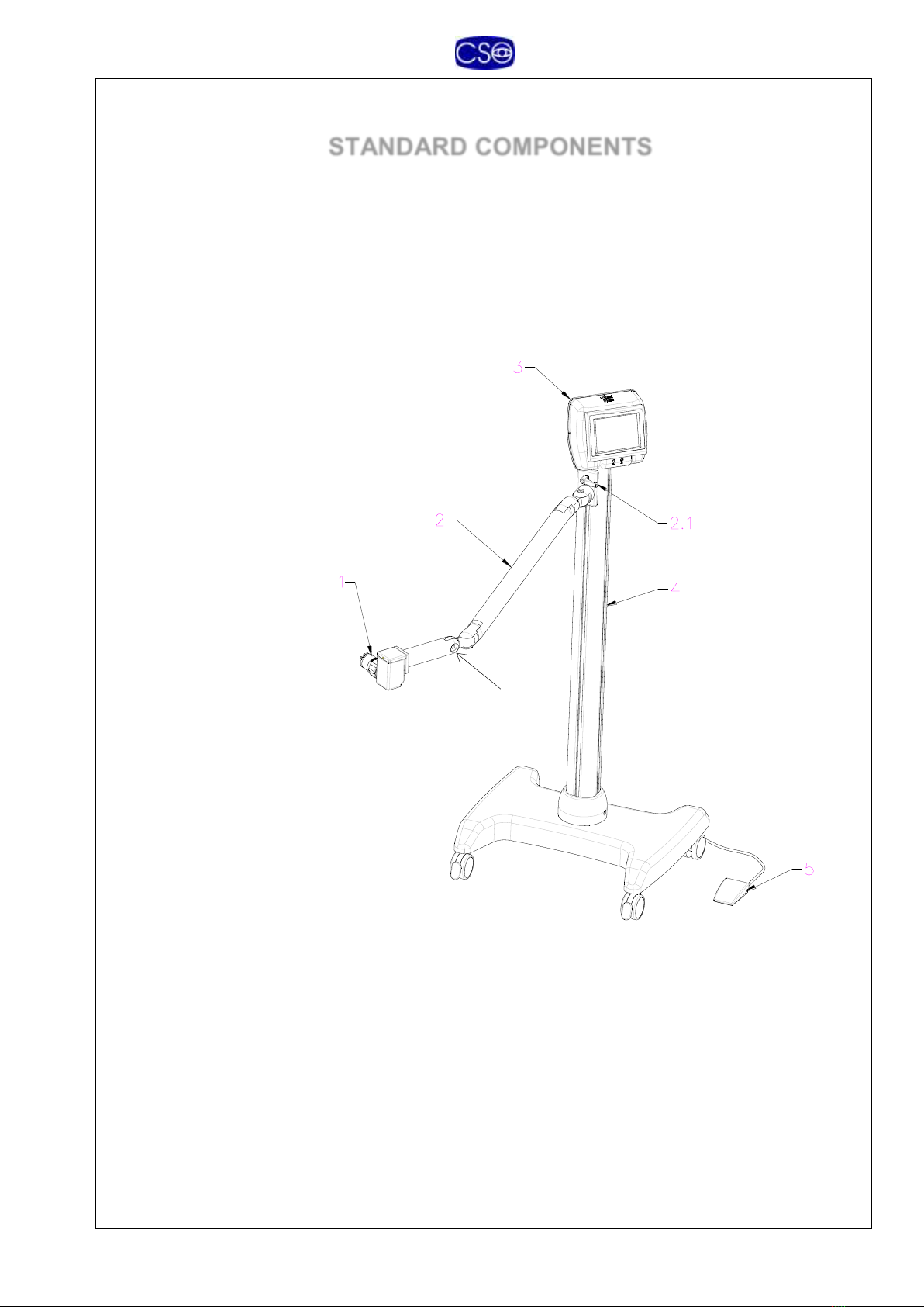
STANDARD COMPONENTS
The devise is composed of the following principal units:
1- OPTICAL HEAD
2- BALANCE ARM
2.3- OPTICAL HEAD LOCK
3- CONTROL BOX
4- STAND
5- FOOT SWITCH
Standard accessories:
- Power cord
- Wrenches for assembly
- UV light meter
- Adapter holder
- This use and maintenance manual.
2.3
Mod. VEGA 10mW -Instructions for Use and Maintenance - rev. 8- Page 5 of 25
Attention!
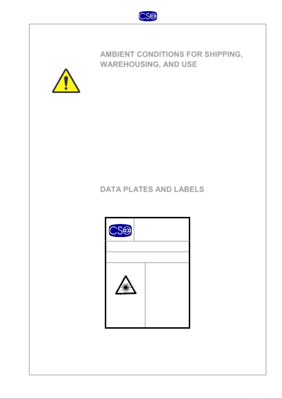
AMBIENT CONDITIONS FOR SHIPPING,
WAREHOUSING, AND USE
As long as the instrument remains in its original packing it may be
exposed to the environmental conditions listed below, for a maximum
of 15 weeks during shipping and warehousing, without suffering
damage:
Temperature between -10 °C and +60 °C,
atmospheric pressure between 500 hPa and 1060 hPa, and
relative humidity between 10% and 90%.
Ambient conditions for operation are, instead:
Temperature between +15 °C e +30 °C;
atmospheric pressure between 700 hPa and 1060 hPa, and
relative humidity between 30% and 75%.
DATA PLATES AND LABELS
C.S.O. srl
Via degli Stagnacci, 12/E
50010 SCANDICCI
(FIRENZE) - ITALY
UV EMITTER Mod. VEGA
SERIAL NUMBER ………………….
LED
APERTURE
INVISIBLE
LED
RADIATION
DO NOT VIEW DIRECTLY
WITH OPTICAL
INSTRUMENTS
CLASS 1M
LED LASER
PRODUCT
(EN 60825-1:2003)
OPTICAL HEAD data plate

Mod. VEGA 10mW -Instructions for Use and Maintenance - rev. 8- Page 6 of 25
C.S.O. srl - Via degli Stagnacci, 12/E
50010 SCANDICCI (FIRENZE) - ITALY
CONTROL BOX
Mod. VEGA
INPUT
100-120 V 18VA
FUSES 2 x 315 mA - 5x20 - T type (IEC 127)
230-240 V 18VA
FUSES 2 x 160 mA - 5x20 - T type (IEC 127)
FREQ. 50/60 Hz
OUTPUT
Emission power: 10 mW
Wavelength: 370 nm
Bandwidth: 8 nm
SERIAL NUMBER
………………….
0051
SEE USER MANUAL
CONTROL BOX data plate
FRONT PANEL
UV ---- Yellow light. Indicates UV-A emission from optical head.
--- Red light. Malfunction indicator.

Mod. VEGA 10mW -Instructions for Use and Maintenance - rev. 8- Page 7 of 25
REAR PANEL
Explanation of Graphics Symbols on Data Plates
Type B. Even though the instrument has no applied
parts as such, the leakage current values are within type B limits
(EN 60601 safety standard for electrical medical devices).
General warning of the user’s duty to read the
instruction manual carefully before installing, commissioning,
and using the instrument.
Ground connection.
0051 “CE mark” attesting to product compliance
with European Union Directive 93/42/EEC (“Medical
Devices”). The code number identifies the notified standards
organization (IMQ) charged with verifying compliance of the
product and the manufacturer’s quality system.
Notice of duty to separately collect and dispose of end-
of-life electrical and electronic equipment (see section on this
topic).

Mod. VEGA 10mW -Instructions for Use and Maintenance - rev. 8- Page 8 of 25
COMMANDS AND SIGNALS
1.3- UV SPOT APERTURE CONTROL
2.1- ARM LOCK
3.1- UV EMISSION INDICATOR (yellow light)
3.2- MALFUNCTION INDICATOR (red light)
3.6- MAIN SWITCH
3.9- CONTROL BOX ROTATION LOCK
5- FOOT SWITCH
Mod. VEGA 10mW -Instructions for Use and Maintenance - rev. 8- Page 9 of 25
Attention!
Before switching on and
using the instrument, read
this manual, and this
chapter in particular,
carefully.
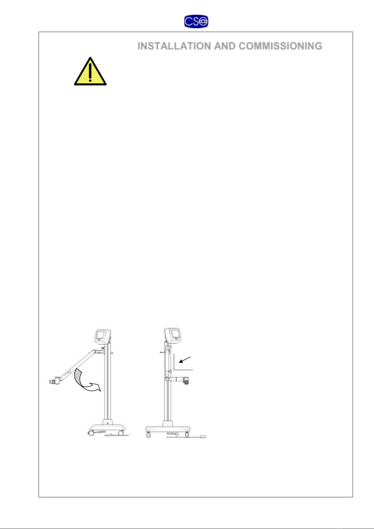
INSTALLATION AND COMMISSIONING
Our instruments are always supplied packed in such a manner as to
best withstand standard shipping and warehousing conditions.
Should you notice defects attributable to shipping when unpacking
the instrument, contact your installation service or the manufacturer.
-Check that your mains voltage is compatible with the
specifications on the data plate of the instrument. If not, contact
the technical assistance center or the manufacturer.
-Your entire electrical system must comply with the CEI 64-4
standard or the more recent CEI 64-8 sect. 710 (Electrical
Systems for Medical Use). In case of doubt, contact your
electrical system installation and maintenance service.
-Never use multiple plugs, adapters, or extension cords to
connect the instrument plug to the mains socket.
-When unplugging the instrument from mains power supply,
even in an emergency, grasp the plug only; never pull the cord
to disconnect the plug.
-In order to avoid interruptions during treatment, we suggest
connecting the instrument through an emergency power supply.
-Do not to touch the video output and the patient at the same
time.
-Please take care during the transportation to avoid the tilting of
the equipment. Please be sure to hold the arm in the lower
position with the final part 90° tilted as indicated in the picture
below
90°
Mod. VEGA 10mW -Instructions for Use and Maintenance - rev. 8- Page 10 of 25
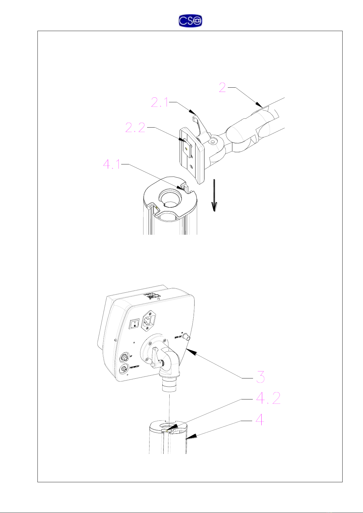
ASSEMBLY
Assemble the arm (2) on the column, inserting the plate (2.2) in the channel (4.1).
Tighten the knob (2.1) to lock in place at correct height.
Insert the optical head (3) onto the column (4).
Adjust rotation friction by tightening the screw (4.2) with the wrench supplied for that
purpose.

Mod. VEGA 10mW -Instructions for Use and Maintenance - rev. 8- Page 11 of 25
Assemble the optical head (1) on the arm attachment (2.2).
Lock in place with the wrench supplied for that purpose. (1.1)
Adjust the optical head in the horizontal position and lock tightly the two screw 34 and
36 on the mechanism 2.3
2.3

Mod. VEGA 10mW -Instructions for Use and Maintenance - rev. 8- Page 12 of 25
CONNECTIONS
1.4- INSERT THE CONNECTOR
3.4- INSERT THE CONNECTOR (foot switch)
3.5- INSERT THE CONNECTOR FROM THE ARM
3.7- INSERT THE SOCKET CONNECTOR IN THE PLUG 3.7 (mains)
3.10- VIDEO OUT
Attention!
ELECTRICAL SAFETY: GENERAL
PRECAUTIONS AND SAFETY WARNINGS
-Never touch the power cord with wet hands. Check frequently that
the cord is so placed as not to be stepped on or crushed by weights.
Never knot the cord.
-A damaged power cord can cause fires or electrical shocks.
Check frequently that the instrument power cord is in good
condition. If it becomes necessary to replace the power cord
supplied with the instrument, contact your supplier.
-Do not perform any repairs or maintenance work on the
instrument or the electrical system beyond what is explained in
this manual.
-Do not use the instrument near water and be careful not to spill
liquids on any part of it. Avoid damp and dusty locations and
locations subject to brusque changes in temperature and
humidity.
-Disconnect the instrument from the mains supply socket before
cleaning and/or disinfecting.

Mod. VEGA 10mW -Instructions for Use and Maintenance - rev. 8- Page 13 of 25
-The device complies with the EMC requirements according to
IEC 60601-1-2. Radio transmitting equipment, cellular phones
etc. shall not be used in the close proximity of the device since
this could influence the performance of the device. Particular
precaution must be considered during use of strong emission
sources such as High Frequency surgical equipment and similar
so that e.g. the HF-cables are not routed on or near the device. If
in doubt, contact qualified medical technician or your local
representative. In the Technical Description, chapter X, technical
details regarding EMC precautions and applicable safety
distances can be found
-The standard-configuration instrument is tested in accordance with
international standards EN 60601-1 “Medical Electrical
Equipment. PART 1: General Requirements for Safety” and EN
60601-1 “Collateral Standard: Safety Requirements for Medical
Electrical Systems” and is fully compliant with these standards.
Note that the standard version unit can be connected to other
instruments, medical electrical and not; CSO cannot test the
compliance of all possible system configurations.
-Any additional accessories (video recorder, monitor, or similar
equipment) connected to the analog or digital interfaces must each
be certified in accordance with the respective pertinent standards.
All such devices must in any case be located outside of the patient
area.
-Once all the equipment making up the system has been connected
and assembled, check that the resulting medical electrical system
complies with the requirements set by EN 60601-1-1 “Collateral
Standard: Safety Requirements for Medical Electrical Systems.”
-Should the leakage current values exceed the limits set by the
pertinent standards, additional safety measures must be adopted as
laid down by the EN 60601-1-1 standard. In this case, the entire
system must be powered through a safety insulating transformer.
-Attention! Do not connect devices not forming part of the system to
the instrument.
Mod. VEGA 10mW -Instructions for Use and Maintenance - rev. 8- Page 14 of 25
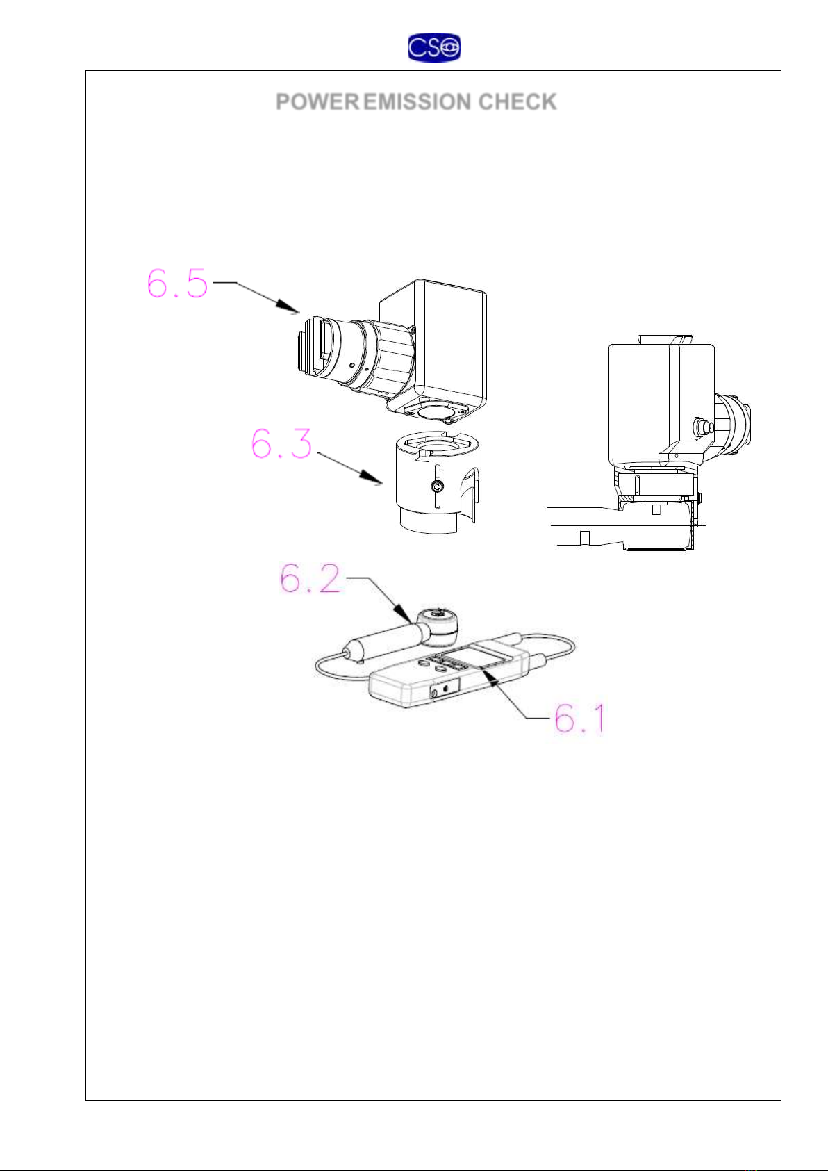
POWEREMISSION CHECK
We recommend checking the intensity of the radiation emitted by the
instrument prior to each treatment.
The system is equipped with a UV meter (6) for checking power
emission. The accessory is composed of a detector head (6.2) and a
display (6.1).
The UV meter is an extremely delicate measurement instrument and it
must therefore be stored and handled with all dued precautions.
When not in use, store the instrument, with its protective
cover, in a safe place not exposed to humidity or sources of
heat.
Do not expose the instrument to extremes of temperature.
Do not expose to strong vibrations.
Do not use near sources of magnetic fields (motors,
transformers, etc.).
Before taking any reading, allow a few minutes’ time on-site
for instrument temperature to stabilize.
Replace the batteries immediately whenever the “BAT”

Mod. VEGA 10mW -Instructions for Use and Maintenance - rev. 8- Page 15 of 25
Attention!
symbol is displayed.
If the instrument is unused for a long period of time, remove
the batteries.
Do not open the instrument or tamper with its parts.
Control and calibration may be performed only at CSO.
For further information regarding the UV meter, refer to the
original instruction manual.
To take a UV reading, proceed as outlined below:
1. Plug the adapter holder 6.3 in to the optical head 6.5
2. Plug the detector head 6.2 in the adapter holder 6.3
3. Check that in the absence of emissions and interference, the
reading on the display (6.1) is “0” with a tolerance of +/-0.05
mW/cm² (zero reference reading).
4. Switch on the main switch (3.6) of the power supply (3).
5. Switch on the UV emitter with the foot switch (5); in the
“POWER ON CHECK” mode. The diaphragm (1.3) must be
adjusted to max exposure 11
6. On the display (6.1), read the power density value expressed
in mW/cm².
7. Press the foot switch again to move ahead to the treatment
phases.
The optimal measured value should be 10 mW/cm², or in any case
within a tolerance range of 9 to 11 mW/cm² otherwise waiting for 15’
in “POWER ON CHECK” mode after that repeat the measurement.
Should the measured value not meet tolerance, check whether or
not:
a) The mains voltage is correct.
b) The cables are connected correctly.
c) The power supply fuses are good.
d) The head of the UV emitter is clean.
e) The UV meter batteries are charged.
f) The procedure described above has been carried out
correctly. Repeat the entire procedure from the
beginning.
If the problem persists despite the above checks, contact your
retailer or CSO.

Mod. VEGA 10mW -Instructions for Use and Maintenance - rev. 8- Page 16 of 25
Attention!
INSTRUCTIONS FOR USE
Switch on the main switch of the instrument (9).
Bring the optical head (1) toward the patient and center the image of
his/her eye at the center of the monitor screen.
For best results, the emitter must be correctly focused; the focus point
is located about 54 mm from the apex of the optical head. For quick
focus search, use the collimating light beams (1.2): two flashing
iridescent lines projected at a certain angle which when their paths
meet at a single point, permit finding the correct focus position (see
figure below).
Correct focusing ensures correct UV emission power density for
meeting medical procedure guidelines (10 mW/cm²) only at this
focus point.
OPTICAL HEAD
LUMINOUS SPOTS FOR FOCUSING
Mod. VEGA 10mW -Instructions for Use and Maintenance - rev. 8- Page 17 of 25
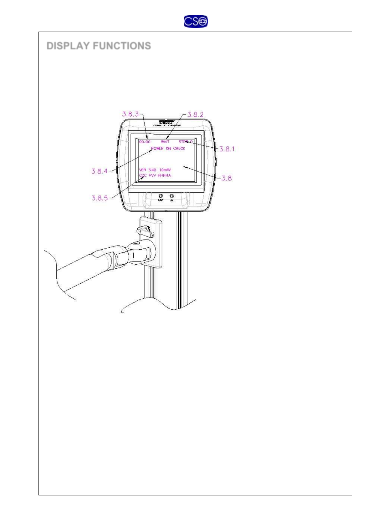
DISPLAY FUNCTIONS
The instrument is equipped with a display (3.8) that supplies all the information relative to the
treatment procedure to be followed. The text line displays the TIME (3.8.3, minutes and seconds)
for each phase, the STATUS (3.8.2), and the single STEP (3.8.1) on which we are working.
STATUS (3.8.2)-
WAIT- The instrument is waiting for a command to begin a phase or the entire
procedure.
RUN- One of the operative phases is running.
PAUSE- The foot switch has been pressed during a phase of the procedure and the
instrument is waiting for new input. Press the foot switch again to resume work from
the point of interruption.
RESET- The foot switch has been held down for 10 seconds and the instrument is
consequently resetting to the top of the first phase.
STEP (3.8.1)-
Step 0 is the phase of imbibition of the cornea with riboflavin.
Step 1 is the UV- treatment phase that will be finished within 9 minutes –the system will
switch off automatically after 9 minutes
TIME (3.8.3)-
The elapsed time for each step is displayed in minutes and seconds.
STATUS (3.8.4)-
Mod. VEGA 10mW -Instructions for Use and Maintenance - rev. 8- Page 18 of 25
POWER ON CHECK- The first phase of operation: the power check to be
conducted with the aid of the UV meter. During this phase, the display show the
version of firmware and the operating parameters that must be communicated in
the event of a request for assistance.
RESUMED- The system has resumed operation from the phase and time at which
power supply was interrupted.
If treatment is interrupted due to failure of the external power supply, the system memorizes the
elapsed treatment time. When the instrument is repowered, treatment can be resumed from the
point in time stored in memory.
TREATMENT PROCEDURE
Position the optical head above the patient and align it, finding the focus point as
described above.
Step 0 imbibition of the cornea with Riboflafin:
oTraditional 15’-30’
oIontophoresis 5’
Press the foot switch to start step 1,
The procedure will be finished in 9 minutes, the system will switch off automatically
Mod. VEGA 10mW -Instructions for Use and Maintenance - rev. 8- Page 19 of 25
TECHNICAL FEATURES
Power supply
Single phase AC mains supply 100, 120, 230, 240 V, 50/60 Hz
Rated power 18 VA (max)
UV source
LED emitting in the UV-A spectrum
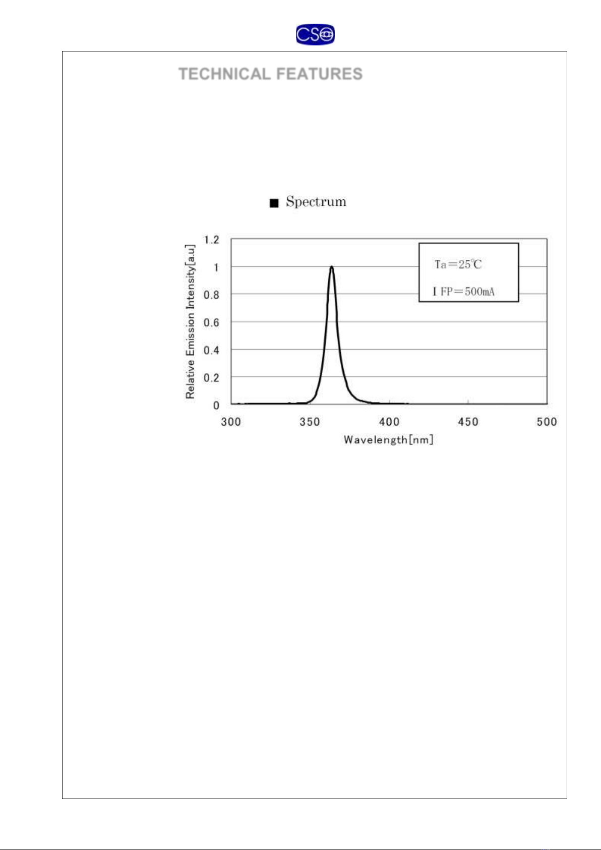
Emission
characteristics
Peak wavelength: 370 nm
Spectrum width: 8 nm (at half amplitude)
Emission spectrum
Radiated power
density
10 mW/cm2(max)
Diameter of
irradiated area
Variable
Min Ø 4mm Max Ø 11 mm
Collimation
1 pair red LEDs
Work distance
54 mm
Fixation
Fixation LED green color
Video camera
In optical head
Minicamera, ¼”, color, model ECH-3030ST
Monitor
Display monitor, 5.6”, color, model SJD-56S
Video out
75-Ohm PAL video-composite output
Dimensions
1260 –545 –1360 mm
Weight
20 kg
Mod. VEGA 10mW -Instructions for Use and Maintenance - rev. 8- Page 20 of 25
REGULATORY COMPLIANCE
INFORMATION
The VEGA is designed and built in compliance with EU
Directive 93/42/EEC and the following harmonized standards:
CEI EN 60601-1:1991 “Medical Electrical Equipment – Part
1: General Requirements for Safety" as amended.
CEI EN 60825-1:2003 –“Safety of Laser Products - Part 1:
Equipment Classification, Requirements, and User Guide.”
CEI EN 60601-1-2:2001 - “Medical Electrical Equipment –
Collateral Standard: Electromagnetic Compatibility.”
EQUIPMENT CLASSIFICATION
According to EN 60601-1
safety standard
Portable device (movable from one location to another).
Protection against direct and indirect electrical shock:
Class I
Type B
Compliance level for protection against humidity:
Common devices (IP20)
(no protection against infiltration of water)
Method of sterilization or disinfection:
Disinfectable device
Compliance level for protection in the presence of inflammable
anesthetic mixtures:
No protection
Use conditions: continuous service
According to CEI EN
60825-1 safety standard
LED RADIATION in the UV-A range, class 1M, for medical
use.
According to Annex IX of
Directive 93/42/EEC
Class II b (Rule 9, Annex IX)
Table of contents
Other CSO Medical Equipment manuals


Popular Medical Equipment manuals by other brands

VAC
VAC 1048 Patient Instructions For Use

RJL systems
RJL systems QUANTUM V SEGMENTAL BIA user manual

Presto
Presto WPS Series Installation, operation and service manual

gbo Medizintechnik
gbo Medizintechnik Sonostat user manual

inhealth
inhealth Blom-Singer Instructions for use

Ultrasonix
Ultrasonix SonixMDP Service manual


