RJL systems QUANTUM V SEGMENTAL BIA User manual


Table of Contents
About US - RJL Systems……………………………………….. 3
System it Contents…………………………..…………….….. 4
Overview of the Quantum V Segmental BIA…………..……… 5
What is measured and saved for analysis ……………..……… 6
Charts and graphs ………………………………………....…… 7
Eight electrode placement ……………………………..….….. 8
Pre-testing protocol for the subject/patient …………………… 11
Performing the segmental BIA test ...…………………...…….. 12
ON – OFF push buttons …………………………………….… 12
Understanding the display screens ………….……………….. 13
Proper care of the analyzer and cables ………….…….…..….. 14
Subject cable information ………………………………….… 15
Using the test resistor to check the analyzer and cables ……... 16
Preparation for subject testing ..……………………………… 17
Troubleshooting Guide ….…………………………………..... 18
RJL Warranty Information …………………………......…….. 19
Appendix ………………………….………………………….. 21
- 2 -
Manual Last Revised
August 1 , 2019

About Us – RJL Systems
RJL SYSTEMS WAS THE FIRST COMPANY TO DEVELOP THE USE OF BIOELECTRICAL
IMPEDANCE ANALYSIS (BIA) TO ASSESS HUMAN BODY COMPOSITION BY
ENGINEERING THE “GOLD STANDARD” OF BIA INSTRUMENTS IN 1981. RJL ANALYZERS
PROVIDE BIA MEASUREMENTS FOR USERS AROUND THE WORLD – THEY ARE
RECOGNIZED AS “RESEARCH QUALITY” BECAUSE OF THEIR REPUTATION FOR
ACCURACY AND RELIABILITY.
RJL has registered patents on our instruments, trademarks, and copyrights on our software and papers.
Customers are buying products directly from the company that develops, engineers, and manufactures
the analyzers – NOT a third party vendor or distributor.
RJL’s Quantum Analyzers have FDA clearance as a Class II medical device for safe use on the human
body to collect BIA data. RJL is registered with the FDA as a Medical Device Manufacturer
(Registration No. 1831675). The Quantum V Segmental BIA System and accompanying software are
marketed under the following FDA clearances: 830292C, 862383, and 070999.
RJL Systems is registered as an ISO-13485 2016 compliant company.
RJL instruments go through a rigorous testing, calibration and inspection process that complies with
ISO standards. Conformity of products and services to International Standards provides assurance about
overall product quality, safety, reliability and accuracy
Any questions or technical support needed regarding our products will be handled by the professionals
who designed and built the analyzers, and the related software
The Company’s 30+ years of engineering expertise and knowledge in BIA science make it uniquely
qualified to provide custom-made instruments of any size or scope
If you sign up for the e-mail newsletter (via website), you will receive information on interesting new
developments in the field of BIA science and/or RJL products (www.rjlsystems.com).
All RJL products come with a warranty and continued technical and product support.
- 3 -

Quantum V Segmental BIA System Kit Contents
•Quantum V Segmental BIA Analyzer
•Two subject cables with protective pouch
•Test resistor and capacitor network
•Four (4) Zip Lock Packs of electrodes ( 800 total electrodes ) 100 tests
•Quantum V Segmental BIA User’s Manual and video (thumb drive)
•BC (Body Composition) Software and User's Manual (thumb drive)
•Carrying Case as shown
- 4 -
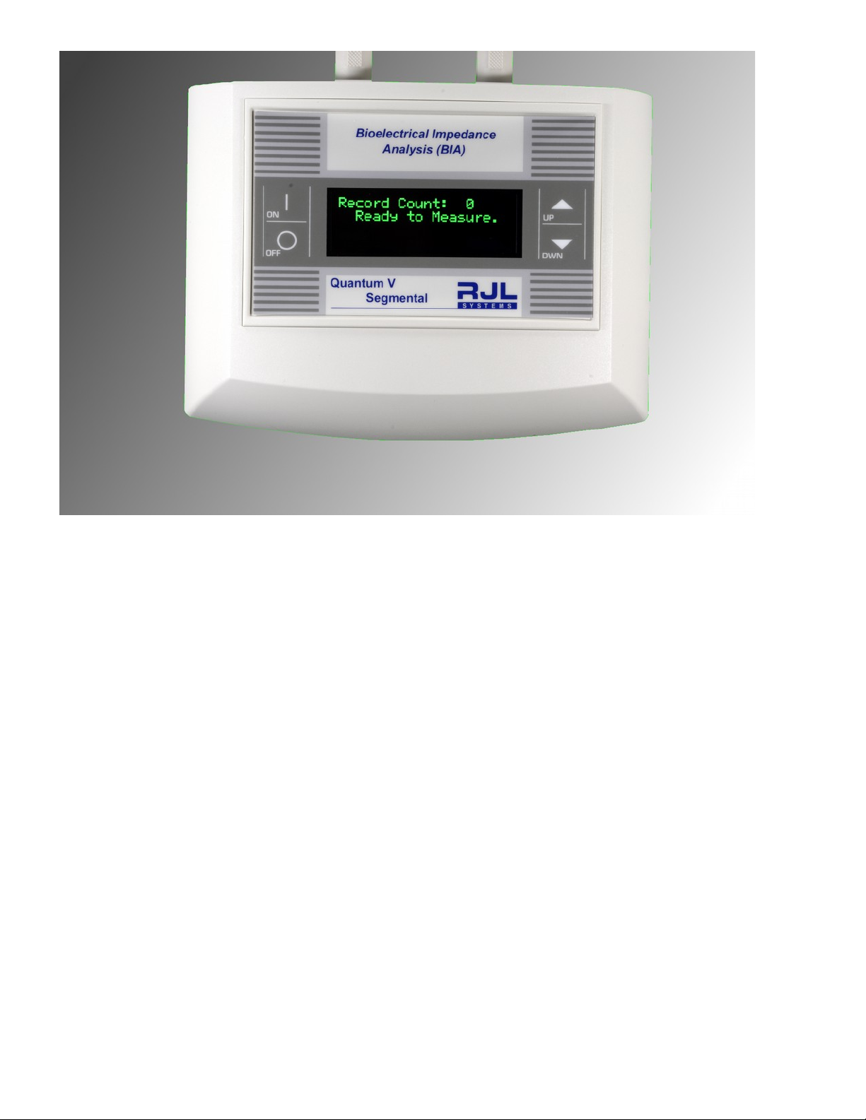
Overview of the Quantum V Segmental BIA
The Quantum V Segmental BIA provides quantitative regional body composition assessments that are
similar to those produced by Dual-energy X-ray Absorptiometry (DXA) scanners. This is performed by
using eight hand and foot electrodes (left and right side) with the subject in a supine position and
measuring 13 resistance and reactance regions on the human body. The comparative characteristics of
segmental body composition assessments are highly significant, as segmental muscle atrophy and
hypertrophy can be clearly illustrated by analyzing and comparing collected data as a comparative
percentage or change over time.
Health care professionals such as physicians who are interested in regional muscle wasting will find the
Quantum V Segmental BIA a valuable tool. In addition, physical therapists, sport medicine trainers and
nutritionists can monitor and track their patient’s progress and health improvements on specific regions
of the body.
The Quantum V Segmental BIA uses an eight lead 12-channel multiplexer to quickly measure
resistance and reactance values from each arm, leg and right and left torso, including the upper and
lower regions of the human body in less than 20 seconds. The repeatability and accuracy of the
resistance and reactance measurements allow the smallest changes to be recorded with 0.1 ohms of
resolution.The phase angle of these regions is also illustrated.
- 5 -
Table of contents
Popular Medical Equipment manuals by other brands


Getinge
Getinge Arjohuntleigh Nimbus 3 Professional Instructions for use

Mettler Electronics
Mettler Electronics Sonicator 730 Maintenance manual

Pressalit Care
Pressalit Care R1100 Mounting instruction

Denas MS
Denas MS DENAS-T operating manual

bort medical
bort medical ActiveColor quick guide

AccuVein
AccuVein AV400 user manual


