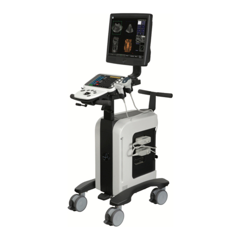
Ultrasonix SonixMDP User manual

SonixMDP/SP/OP Ultrasound System
Service Manual


SonixMDP/SP/OP Service Manual 00.053.101, Revision C
Ultrasonix Medical Corporation
SonixMDP/SP/OP Ultrasound System
Service Manual
Ultrasonix Medical Corporation
130 - 4311 Viking Way
Richmond, BC V6V 2K9
Canada
www.ultrasonix.com
1.866.437.9508
1.604.279.8550
1.778.296.3860 (Support)
© 2013 Ultrasonix Medical Corporation
00.053.101, Revision C, March 27, 2013
All Rights Reserved. Printed in Canada.
US Patents 6,216,029 - 6,325,759 - 6,558,326 - 6,911,008 - 7,274,325 - 8,088,070 - D654,178


SonixMDP/SP/OP Service Manual 00.053.101, Revision C Table of Contents
i
TABLE OF CONTENTS
CHAPTER 1: GENERAL INFORMATION...................................................................................................................................................... 1-1
1.1 AUDIENCE .................................................................................................................................................................................................... 1-1
1.1.1 Prescription Device ................................................................................................................................................................................. 1-1
1.2 VOLTAGE DISCLAIMER ............................................................................................................................................................................... 1-1
1.3 CONNECTIVITY DISCLAIMER ..................................................................................................................................................................... 1-1
1.4 PRIVACY DISCLAIMER ................................................................................................................................................................................ 1-1
1.5 SERVICE DISCLAIMER ................................................................................................................................................................................ 1-1
1.6 LICENSE AGREEMENT................................................................................................................................................................................ 1-2
1.7 TRADEMARKS AND PATENTS.................................................................................................................................................................... 1-2
1.8 SYSTEM OVERVIEW.................................................................................................................................................................................... 1-3
1.9 PHYSICAL DESCRIPTION ........................................................................................................................................................................... 1-4
1.9.1 LCD Display ............................................................................................................................................................................................ 1-4
1.9.2 Operator Console.................................................................................................................................................................................... 1-4
1.9.3 Modulo .................................................................................................................................................................................................... 1-4
1.9.4 Transducers ............................................................................................................................................................................................ 1-4
1.9.5 UPS......................................................................................................................................................................................................... 1-4
CHAPTER 2: SYSTEM SPECIFICATIONS.................................................................................................................................................... 2-1
2.1 DIMENSIONS ................................................................................................................................................................................................ 2-1
2.2 ELECTRICAL RATINGS................................................................................................................................................................................ 2-1
2.3 VOLTAGE ADJUSTMENT............................................................................................................................................................................. 2-1
CHAPTER 3: SYSTEM INSTALLATION........................................................................................................................................................ 3-1
3.1 INSTALLATION ISSUES AND REQUIREMENTS ........................................................................................................................................ 3-1
3.1.1 Environmental Requirements.................................................................................................................................................................. 3-1
3.1.2 Electrical Requirements .......................................................................................................................................................................... 3-2
3.1.2.1 Instrument Input Power Rating.......................................................................................................................................................... 3-2
3.1.3 Electrostatic Discharge ........................................................................................................................................................................... 3-3
3.1.4 Electromagnetic and Radio Frequency Interference............................................................................................................................... 3-3
3.1.5 Wiring Requirements .............................................................................................................................................................................. 3-4
3.1.5.1 Main AC Connection.......................................................................................................................................................................... 3-4
3.1.5.2 Ethernet (Hard-Wired) Network Connection...................................................................................................................................... 3-4
3.1.5.3 Image Management Network ............................................................................................................................................................ 3-4
3.2 PRE-INSTALLATION..................................................................................................................................................................................... 3-5
3.2.1 Preliminary Inspection............................................................................................................................................................................. 3-5
3.2.2 SonixMDP/SP/OP Uncrating Instructions ............................................................................................................................................... 3-6
3.3 INSTALLATION ........................................................................................................................................................................................... 3-12
3.3.1 Mechanical Inspection .......................................................................................................................................................................... 3-12
3.3.1.1 Wheels ............................................................................................................................................................................................ 3-12
3.3.1.2 LCD Display..................................................................................................................................................................................... 3-12
3.3.1.3 Console Height, Angle and Swivel Adjustment ............................................................................................................................... 3-13
3.3.2 EMI Filter and Power Panel .................................................................................................................................................................. 3-14
3.3.2.1 Voltage Configuration ...................................................................................................................................................................... 3-14
3.3.3 Powering the System ............................................................................................................................................................................ 3-16
3.3.3.1 Turning on Main Power Switch........................................................................................................................................................ 3-16
3.3.3.2 Changing Fuses .............................................................................................................................................................................. 3-17
3.3.4 UPS Configuration (SonixMDP and SonixSP only) .............................................................................................................................. 3-18
3.3.5 Transducer Inspection .......................................................................................................................................................................... 3-20
3.3.6 System Initialization .............................................................................................................................................................................. 3-20
3.3.7 Peripherals............................................................................................................................................................................................ 3-21
3.3.7.1 Printer Installation (without Peripheral Tray).................................................................................................................................... 3-21
3.3.7.2 Barcode Reader .............................................................................................................................................................................. 3-22

Table of Contents 00.053.101, Revision C SonixMDP/SP/OP Service Manual
ii
CHAPTER 4: PERFORMANCE TESTING ..................................................................................................................................................... 4-1
4.1 CONSOLE TEST ............................................................................................................................................................................................4-1
4.2 IMAGE TEST ..................................................................................................................................................................................................4-2
4.3 REMOVABLE HARDWARE (IF APPLICABLE)..............................................................................................................................................4-2
4.4 UPS TEST (IF APPLICABLE).........................................................................................................................................................................4-2
4.5 PULSED DOPPLER SOUND TEST ...............................................................................................................................................................4-3
4.6 LICENSES......................................................................................................................................................................................................4-3
CHAPTER 5: SOFTWARE ............................................................................................................................................................................. 5-1
5.1 SOFTWARE UPDATES .................................................................................................................................................................................5-1
5.1.1 Software Update via the Internet .............................................................................................................................................................5-1
5.1.2 Software Update via a Downloaded File..................................................................................................................................................5-2
5.2 PATIENT DATABASE REPAIR......................................................................................................................................................................5-3
5.3 SYSTEM RECOVERY....................................................................................................................................................................................5-3
CHAPTER 6: PERIPHERALS AND ACCESSORIES .................................................................................................................................... 6-1
6.1 PERIPHERAL COMPONENTS .....................................................................................................................................................................6-1
6.1.1 Local Printer Setup ..................................................................................................................................................................................6-1
6.1.2 Network Printer Setup..............................................................................................................................................................................6-2
6.1.3 Configuring Custom Keys ........................................................................................................................................................................6-4
6.1.3.1 Paper Printing Configuration ..............................................................................................................................................................6-4
6.1.3.2 Trigger Configuration..........................................................................................................................................................................6-4
6.1.3.3 Image Sheet Printing..........................................................................................................................................................................6-5
6.2 ACCESSORIES..............................................................................................................................................................................................6-6
6.2.1 Transducers ............................................................................................................................................................................................6-6
CHAPTER 7: FIELD SERVICE COMPONENTS............................................................................................................................................ 7-1
7.1 PROTECTING PATIENT DATA .....................................................................................................................................................................7-1
7.1.1 Exporting User Data (As Required) .........................................................................................................................................................7-1
7.1.2 Importing User Data (As Required) .........................................................................................................................................................7-3
7.1.3 Exporting Patient/Exam Data (As Required) ...........................................................................................................................................7-5
7.1.4 Importing Patient/Exam Data (As Required)............................................................................................................................................7-6
7.1.5 Backing up/Exporting Patient Data via the Service Mode Option............................................................................................................7-7
7.1.6 Restoring/Importing Patient Data via the Service Mode Option ..............................................................................................................7-9
7.2 TURNING THE UPS BREAKERS ON AND OFF ......................................................................................................................................... 7-11
7.2.1 Determining Whether the UPS Breakers are ON or OFF ...................................................................................................................... 7-11
7.2.2 Turning OFF/Resetting the UPS Breakers ........................................................................................................................................... 7-11
7.2.3 Turning ON the UPS Breakers ..............................................................................................................................................................7-12
7.3 ACCESSING THE MODULO .......................................................................................................................................................................7-13
7.3.1 Removing the Side Shrouds..................................................................................................................................................................7-13
7.3.2 Replacing the Side Shrouds ..................................................................................................................................................................7-16
7.4 REPLACING THE MODULO........................................................................................................................................................................7-18
7.4.1 Removing the Modulo............................................................................................................................................................................7-18
7.4.2 Installing the Modulo..............................................................................................................................................................................7-20
7.4.3 Connectivity ...........................................................................................................................................................................................7-22
7.4.3.1 System Case Connectivity Panels ...................................................................................................................................................7-22
7.4.3.2 Back Connectivity Panel ..................................................................................................................................................................7-26
7.4.3.3 Console Connectivity .......................................................................................................................................................................7-27
7.4.4 Testing the Modulo and UPS .................................................................................................................................................................7-27
7.4.5 Testing the Modulo (No UPS Installed)..................................................................................................................................................7-28
7.5 FRONT BLOCK/ULTRASOUND MODULE SERVICING .............................................................................................................................7-28
7.5.1 Accessing the Front Block/Ultrasound Module (Without Removing the Modulo) ..................................................................................7-28
7.5.2 Opening the Front Block/Ultrasound Module.........................................................................................................................................7-29
7.5.3 Removing the Front Block/Ultrasound Module ......................................................................................................................................7-31
7.5.4 Reinstalling the Front Block/Ultrasound Module....................................................................................................................................7-33
7.5.5 Closing the Front Block/Ultrasound Module ..........................................................................................................................................7-36
7.6 MODULO – INTERNAL COMPONENT REPLACEMENT............................................................................................................................7-37
7.6.1 Removing the Hard Drives.....................................................................................................................................................................7-37
7.6.2 Replacing the CPU Fan .........................................................................................................................................................................7-39
7.6.3 Replacing/Reseating Cards...................................................................................................................................................................7-40

SonixMDP/SP/OP Service Manual 00.053.101, Revision C Table of Contents
iii
7.7 ECG SERVICING ........................................................................................................................................................................................ 7-41
7.8 LCD DISPLAY SERVICING......................................................................................................................................................................... 7-41
7.9 SPEAKER SERVICING ............................................................................................................................................................................... 7-42
7.10 CONSOLE SERVICING .............................................................................................................................................................................. 7-42
7.11 WHEEL REPLACEMENT ............................................................................................................................................................................ 7-42
7.12 UPS SERVICING......................................................................................................................................................................................... 7-42
7.12.1 Shipping the UPS for Service/Repair/Replacement.............................................................................................................................. 7-42
7.13 BARCODE READER SERVICING .............................................................................................................................................................. 7-43
7.14 TRANSDUCER TESTING............................................................................................................................................................................ 7-44
7.14.1 Testing the Transducer ......................................................................................................................................................................... 7-44
7.14.2 Testing the Transducer Board............................................................................................................................................................... 7-45
7.15 MISCELLANEOUS PARTS ......................................................................................................................................................................... 7-46
7.15.1 Transducers Holders and Cable Hooks ................................................................................................................................................ 7-46
7.15.2 Peripheral Tray ..................................................................................................................................................................................... 7-47
7.15.2.1 Attaching/Detaching the Peripheral Tray Basket ............................................................................................................................. 7-47
7.16 RETURNING PARTS FOR SERVICE/REPAIR/REPLACEMENT............................................................................................................... 7-48
7.16.1 Transducers .......................................................................................................................................................................................... 7-48
7.16.2 UPS Battery .......................................................................................................................................................................................... 7-48
CHAPTER 8: DICOM...................................................................................................................................................................................... 8-1
8.1 DICOM CONFIGURATION............................................................................................................................................................................ 8-2
8.1.1 Global Settings........................................................................................................................................................................................ 8-2
8.1.2 DICOM Storage Settings......................................................................................................................................................................... 8-3
8.1.3 DICOM Print Settings.............................................................................................................................................................................. 8-9
8.1.4 DICOM Worklist Settings ...................................................................................................................................................................... 8-14
CHAPTER 9: NETWORK CONFIGURATION................................................................................................................................................ 9-1
9.1 NETWORK .................................................................................................................................................................................................... 9-1
9.1.1 Ethernet (LAN) Network Configuration ................................................................................................................................................... 9-3
9.1.1.1 Ethernet (LAN) Communication Test................................................................................................................................................. 9-3
9.1.2 Dialup Network Configuration (If Available) ........................................................................................................................................... 9-4
9.1.2.1 Dialup Communication Test............................................................................................................................................................... 9-4
9.1.3 Wireless Configuration............................................................................................................................................................................ 9-5
9.1.3.1 Wireless Communication Test ........................................................................................................................................................... 9-6
9.2 REMOTE SUPPORT ..................................................................................................................................................................................... 9-7
CHAPTER 10: LICENSE.TXT IMPORTATION ............................................................................................................................................ 10-1
10.1 OBTAIN AND COPY LICENSE.TXT ONTO THE SYSTEM ........................................................................................................................ 10-1
10.2 RE-IMPORT LICENSE.TXT ........................................................................................................................................................................ 10-2
CHAPTER 11: MAINTENANCE ....................................................................................................................................................................11-1
11.1 RECOMMENDED FREQUENCY OF MAINTENANCE PROCEDURES......................................................................................................11-1
11.2 SYSTEM CLEANING....................................................................................................................................................................................11-2
11.2.1 LCD Display and Cabinet ......................................................................................................................................................................11-2
11.2.1.1 LCD Display Cabinet ........................................................................................................................................................................11-2
11.2.1.2 LCD Display Screen ........................................................................................................................................................................11-2
11.2.2 Touch Screen ........................................................................................................................................................................................11-3
11.2.3 Operator Console ..................................................................................................................................................................................11-3
11.2.4 Power Cord ...........................................................................................................................................................................................11-3
11.2.5 Barcode Reader ....................................................................................................................................................................................11-3
11.2.6 Wireless Adapter (When Connected Externally) ...................................................................................................................................11-4
11.2.7 Transducer Holders and Cable Hooks ..................................................................................................................................................11-4
11.2.8 Peripheral Tray and Basket ..................................................................................................................................................................11-4
11.2.9 SonixGPS™...........................................................................................................................................................................................11-4
11.2.10 System Filter ..........................................................................................................................................................................................11-5
11.2.10.1Cleaning the System Filter ..............................................................................................................................................................11-5
11.2.10.2Cleaning the Cleaning Modulo Fan and Exhaust Filters ..................................................................................................................11-6
11.2.11 Fans .......................................................................................................................................................................................................11-7

Table of Contents 00.053.101, Revision C SonixMDP/SP/OP Service Manual
iv
11.3 TRANSDUCER MAINTENANCE.................................................................................................................................................................. 11-8
11.3.1 Usage Guidelines .................................................................................................................................................................................. 11-8
11.3.2 Ultrasound Coupling Gels...................................................................................................................................................................... 11-9
11.3.3 General Transducer Maintenance ...................................................................................................................................................... 11-10
11.3.3.1 Inspection and Testing ................................................................................................................................................................... 11-10
11.3.3.2 Storing and Packaging ................................................................................................................................................................... 11-10
11.3.4 General Transducer Cleaning/Disinfecting Recommendations and Warnings ................................................................................... 11-11
11.3.5 Cleaning/Disinfecting Non-Invasive Transducers ................................................................................................................................11-12
11.3.5.1 Cleaning Non-Invasive Transducers .............................................................................................................................................. 11-13
11.3.5.2 Disinfecting Non-Invasive Transducers.......................................................................................................................................... 11-13
11.3.6 Cleaning/Disinfecting Endocavity Transducers ................................................................................................................................... 11-14
11.3.7 Sterilization .......................................................................................................................................................................................... 11-15
11.4 SHIPPING TRANSDUCERS FOR SERVICE............................................................................................................................................. 11-15
CHAPTER 12: TROUBLESHOOTING ISSUES ........................................................................................................................................... 12-1
12.1 SYSTEM NOT POWERING UP ...................................................................................................................................................................12-1
12.2 SYSTEM HAS POWER BUT IS NOT POWERING UP................................................................................................................................12-1
12.3 NO PRIMARY HARD DRIVE DETECTED ...................................................................................................................................................12-2
12.4 SYSTEM POWERS ON, LCD DISPLAY SHOWS MBR ERROR 1 .............................................................................................................12-2
12.5 SYSTEM SEEMS SLOW..............................................................................................................................................................................12-2
12.6 SYSTEM FREEZES DURING USE..............................................................................................................................................................12-3
12.7 IMAGE IS GRAINY OR MISSING ................................................................................................................................................................12-3
12.8 IMAGE HAS BLACK OR DARK AREAS ......................................................................................................................................................12-3
12.9 IMAGE HAS WAVY INTERFERENCE .........................................................................................................................................................12-4
12.10 IMAGE HAS THREE (3) UNIFORM BLACK AREAS (LEFT, MIDDLE, RIGHT) ..........................................................................................12-4
12.11 REGEDIT......................................................................................................................................................................................................12-4
12.12 LCD DISPLAY BLANK, TOUCH SCREEN DISPLAYS CORRECTLY .........................................................................................................12-4
12.13 LCD DISPLAY BLANK, TOUCH SCREEN DISPLAYS ULTRASONIX LOGO ONLY ..................................................................................12-4
12.14 LCD DISPLAY WORKS, BUT TOUCH SCREEN STILL DISPLAYS ULTRASONIX LOGO EVEN IN IMAGING MODE.............................12-4
12.15 SYSTEM DOES NOT BOOT, ERROR DISPLAYED ON LCD DISPLAY.....................................................................................................12-5
12.16 INITIALIZATION FAILURES.........................................................................................................................................................................12-5
12.16.1 Electronics Initialization Failure .............................................................................................................................................................12-5
12.16.2 Memory Tests Failure (at Initialization) ..................................................................................................................................................12-6
12.16.3 Failed DL Memories Test .......................................................................................................................................................................12-6
12.16.4 Connecting to Console Failure (at Initialization) ....................................................................................................................................12-6
12.16.5 System Hangs when Loading Maps (at Initialization) ............................................................................................................................12-6
12.16.6 Online Support Failure (at Initialization).................................................................................................................................................12-6
12.16.7 Successful Initialization but no Ultrasound Image .................................................................................................................................12-6
12.16.8 Successful Initialization but only 4DC7-3/40 Transducer is Detected....................................................................................................12-7
12.17 NO NETWORK CONNECTION VIA ETHERNET CABLE............................................................................................................................12-7
12.18 TRANSDUCER CONNECTION PORT NOT FUNCTIONING ......................................................................................................................12-7
12.19 CURSOR MISSING OR DISAPPEARS .......................................................................................................................................................12-7

SonixMDP/SP/OP Service Manual 00.053.101, Revision C Table of Contents
v
APPENDIX A: TROUBLESHOOTING SOLUTIONS......................................................................................................................................A-1
A.1 SYSTEM NOT POWERING UP .................................................................................................................................................................... A-1
A.1.1 Test System Power Up............................................................................................................................................................................ A-1
A.2 SYSTEM HAS POWER BUT IS NOT POWERING UP................................................................................................................................. A-1
A.2.1 Check Internal Modulo Power Connections............................................................................................................................................ A-1
A.3 SYSTEM POWERS ON, LCD DISPLAY SHOWS MBR ERROR 1............................................................................................................... A-2
A.4 SYSTEM SEEMS SLOW............................................................................................................................................................................... A-2
A.4.1 Clear RAM .............................................................................................................................................................................................. A-2
A.4.2 Undetected RAM..................................................................................................................................................................................... A-2
A.4.3 Check Custom Keys Settings ................................................................................................................................................................. A-2
A.4.4 Check DICOM Settings .......................................................................................................................................................................... A-3
A.4.5 Clear DICOM Settings ............................................................................................................................................................................ A-3
A.4.6 Cleanup System...................................................................................................................................................................................... A-3
A.4.7 Delete Older LUTS Files ......................................................................................................................................................................... A-3
A.4.8 Delete Older LOG Files........................................................................................................................................................................... A-3
A.5 SYSTEM FREEZES DURING USE............................................................................................................................................................... A-4
A.5.1 Test RAM Chips ...................................................................................................................................................................................... A-4
A.6 IMAGE IS GRAINY........................................................................................................................................................................................ A-4
A.6.1 Adjust the Clarity Setting......................................................................................................................................................................... A-4
A.6.2 Check the Clarity License Status ............................................................................................................................................................ A-4
A.6.3 Re-Import License.txt.............................................................................................................................................................................. A-5
A.7 IMAGE HAS THREE (3) UNIFORM BLACK AREAS (LEFT, MIDDLE, RIGHT) ........................................................................................... A-5
A.7.1 Test US Module....................................................................................................................................................................................... A-5
A.8 REGEDIT – ENSURE SETTINGS ARE CORRECT ..................................................................................................................................... A-6
A.9 LCD DISPLAY BLANK, TOUCH SCREEN DISPLAYS CORRECTLY .......................................................................................................... A-7
A.9.1 Reset LCD Display to Factory Defaults .................................................................................................................................................. A-7
A.9.2 Create a Temporary Video Connection/Restore LCD Display with Tech Support Help .......................................................................... A-7
A.10 LCD DISPLAY BLANK, TOUCH SCREEN DISPLAYS ULTRASONIX LOGO ONLY ................................................................................... A-7
A.10.1 Check Trackball and Mouse Port Connections....................................................................................................................................... A-7
A.10.2 Check for Interference from a USB Device............................................................................................................................................. A-7
A.11 LCD DISPLAY WORKS, BUT TOUCH SCREEN STILL DISPLAYS ULTRASONIX LOGO EVEN IN IMAGING MODE.............................. A-8
A.11.1 Check the Serial Cable Connection........................................................................................................................................................ A-8
A.11.2 Check the Serial Expansion Card Driver ................................................................................................................................................ A-8
A.12 INITIALIZATION FAILURES.......................................................................................................................................................................... A-8
A.12.1 Electronics Initialization Failure – Hardware Test Software ................................................................................................................... A-8
A.12.2 Failed DL Memories Test ...................................................................................................................................................................... A-10
A.12.3 Check Serial Port Configuration for Corruption..................................................................................................................................... A-10
A.12.4 System Hangs When Loading Maps (at Initialization) .......................................................................................................................... A-10
A.12.5 Online Support Failure (at Initialization)................................................................................................................................................ A-10
A.12.6 Successful Initialization but no Ultrasound Image ................................................................................................................................ A-11
A.13 NO NETWORK CONNECTION VIA ETHERNET CABLE........................................................................................................................... A-11
A.13.1 Loose or Faulty Network Cable Connections........................................................................................................................................ A-11
A.13.2 BIOS Network Configuration (for two (2) Network Ports)...................................................................................................................... A-11
A.14 TRANSDUCER CONNECTION PORT NOT FUNCTIONING ..................................................................................................................... A-12
APPENDIX B: ELECTROMAGNETIC IMMUNITY TABLES..........................................................................................................................B-1
APPENDIX C: ULTRASONIX LIMITED WARRANTY ...................................................................................................................................C-1
APPENDIX D: SERVICE DRAWINGS ..........................................................................................................................................................D-1

Table of Contents 00.053.101, Revision C SonixMDP/SP/OP Service Manual
vi

SonixMDP/SP/OP Service Manual 00.053.101, Revision C List of Service Drawings
i
LIST OF SERVICE DRAWINGS
SonixMDP/SP/OP Exploded Overview ..........................................................................................................................................................D-3
Remove LCD Display .....................................................................................................................................................................................D-4
LCD Display and/or Speaker Replacement ....................................................................................................................................................D-5
Console Access .............................................................................................................................................................................................D-6
Console Removal ...........................................................................................................................................................................................D-7
Console Mount (Including Tilt and Swivel) .....................................................................................................................................................D-8
Side Shroud Removal ....................................................................................................................................................................................D-9
Modulo Removal ..........................................................................................................................................................................................D-10
Front Block Removal .................................................................................................................................................................................... D-11
ECG Module Removal/Replacement ...........................................................................................................................................................D-12
UPS Removal ...............................................................................................................................................................................................D-13
UPS Battery Removal ..................................................................................................................................................................................D-14
Wheel Replacement .....................................................................................................................................................................................D-15
Filter Removal/Replacement ........................................................................................................................................................................D-16

List of Service Drawings 00.053.101, Revision C SonixMDP/SP/OP Service Manual
ii

SonixMDP/SP/OP Service Manual 00.053.101, Revision C Chapter 1: General Information
1-1
CHAPTER 1: GENERAL INFORMATION
1.1 AUDIENCE
The intended audience of this service manual is properly trained field and in-house service personnel. This system is a
medical device containing several circuit boards, extensive service diagnostics, and complex operating software. For these
reasons, Ultrasonix recommends that only trained, certified technical support representatives service this ultrasound system.
1.1.1 Prescription Device
1.2 VOLTAGE DISCLAIMER
The system voltage setting is configured in the factory.
It is the user's responsibility to ensure the system is used only under the electrical conditions dictated by Ultrasonix Medical
Corp. Failure to comply with these conditions may result in damage to the system which is not covered by the Ultrasonix
warranty.
1.3 CONNECTIVITY DISCLAIMER
1.4 PRIVACY DISCLAIMER
To protect patient data, Ultrasonix strongly recommends regular patient/image file back-up and purging of older patient files
stored on the system. Refer to Chapter 9 in the relevant user manual for details on transferring patient data.
1.5 SERVICE DISCLAIMER
Sonix Ultrasound Systems are configured with a variety of options that may not be available on all platforms. Therefore, some
service instructions will apply only to specific models/configurations.
Caution: United States law restricts this device to sale or use by, or on the order of a Physician.
Caution: For users running the 100V-120V system, always ensure the utility supply voltage is 100V-120V @ 50/60 Hz.
For users running the 200V–240V system, always ensure the utility supply voltage is 200V-240V @ 50/60 Hz.
Caution: System networking options are intended for use inside your organization's firewall. Organizations that elect to
configure/use the networking functionality provided by Ultrasonix are assuming all liabilities and risks associated with
that decision.
Caution: For details on FCC regulations as they apply to the wireless adapter, please refer to the manufacturer's User Guide
included with the system.
IMPORTANT: The contents of the system hard drive may include Personal Health Information that must be protected as
dictated by local or state laws (for example, Federal Privacy Act or the Health Insurance Portability & Accountability Act
(HIPAA)). In order to ensure regulatory compliance, Ultrasonix will not remove the system hard drive – and the patient
data it contains – from the customer site.
In the event the hard drive must be removed from the system, it will be returned to the customer. Final disposition of the
hard drive and its data will remain the customer's responsibility.

Chapter 1: General Information 00.053.101, Revision C SonixMDP/SP/OP Service Manual
1-2
1.6 LICENSE AGREEMENT
Portions of the Sonix computer programs have been patented by Ultrasonix Medical Corporation (Ultrasonix) or are patent
pending, and are licensed under the following software license agreement:
Ultrasonix, or its suppliers, retain(s) ownership of and title to any computer program supplied with the Equipment and to the
trade secrets embodied in such computer programs. Subject to the Buyer’s acceptance and fulfillment of the obligations in
this paragraph, Ultrasonix grants the Buyer a personal, non-transferable, perpetual, non-exclusive license to use any
computer program supplied with the Equipment that is necessary to operate the Equipment solely on the medium in which
such program is delivered for the purpose of operating the Equipment in accordance with the instructions set forth in the
operator’s manuals supplied with the Equipment and for no other purpose whatsoever. Buyer may not reverse – assemble,
reverse – compile or otherwise reverse – engineer such computer programs nor may Buyer make a copy of such program or
apply any techniques to derive the trade secrets embodied therein. In the event of a failure by Buyer to comply with the terms
of this license, the license granted by this paragraph shall terminate. Further, because unauthorized use of such computer
programs will leave Ultrasonix without an adequate remedy at law, Buyer agrees that injunctive or other equitable relief will be
appropriate to restrain such use, threatened or actual. Buyer further agrees that (i) any of the Ultrasonix suppliers of software
is a direct and intended beneficiary of this end-user sublicense and may enforce it directly against Buyer with respect to
software supplied by such supplier, and (ii) NO SUPPLIER OF ULTRASONIX SHALL BE LIABLE TO BUYER FOR ANY
GENERAL, SPECIAL, DIRECT, INDIRECT, CONSEQUENTIAL INCIDENTAL OR OTHER DAMAGES ARISING OUT OF
THE SUBLICENSE OF THE COMPUTER PROGRAMS SUPPLIED WITH THE EQUIPMENT.
1.7 TRADEMARKS AND PATENTS
Ultrasonix Sonix systems are protected under US Patents 6,216,029 - 6,325,759 - 6,558,326 - 6,911,008 - 7,274,325 -
8,088,070 - D654,178.
SonixGPS™ is a trademark of Ultrasonix Medical Corporation.
Windows© is a trademark of Microsoft Corporation.
DICOM® (Digital Imaging and Communications in Medicine) is the registered trademark of the National Electrical
Manufacturers Association (NEMA) for its standards publications relating to digital communications of medical information.
All other products and brand names mentioned in this document are trademarks of their respective companies.

SonixMDP/SP/OP Service Manual 00.053.101, Revision C Chapter 1: General Information
1-3
1.8 SYSTEM OVERVIEW
The SonixMDP/SP/OP Ultrasound System is a software driven, ergonomic, diagnostic medical device. It uses state of the art
technologies to acquire, process and display ultrasound data (Figure 1-1).
The system has several major field serviceable components including: LCD display with built-in speakers and a multi-
position, articulated lift system, operator console, modulo, transducers and UPS.
Figure 1-1: SonixMDP/SP/OP Ultrasound System
Table 1-1: SonixMDP/SP/OP Ultrasound System
1LCD Display
2Operator Console with Touch Screen
3Front Pull Handles
4Rear Pull Handles
5System Case with three (3) Transducer Ports
6Modulo
7Optional Uninterruptible Power Supply (UPS) with external Breaker access (SonixMDP and SonixSP only)
8Foot Pedal (for Console height adjustment)
1
2
3
4
6
8
5
7

Chapter 1: General Information 00.053.101, Revision C SonixMDP/SP/OP Service Manual
1-4
1.9 PHYSICAL DESCRIPTION
1.9.1 LCD Display
The monitor is a Liquid Crystal Display (LCD display) with an operating resolution of 1024x768 pixels @ 60Hz
(Hertz) and built-in speakers.
1.9.2 Operator Console
The console incorporates a sleek, yet conservative design with easy to reach function controls, consisting of a
keyboard, trackball, push buttons, sliders, dials, rocker switches and an 8.4" (21.34cm), color touch screen. The
three console (and LCD display) adjustments (Height, swivel and tilt) enhance system ergonomics.
1.9.3 Modulo
The modulo is the heart of the system. The system CPU as well as the ultrasound module – in the form of system
boards and electronics – are encased in an aircraft grade aluminum composite case for ease of service.
1.9.4 Transducers
Ultrasonix offers a wide selection of high performance transducers for a variety of imaging applications.
Incorporating the latest acoustic materials and technology, these lightweight transducers are ergonomic and
durable for maximum clinical use. Refer to 6.2.1 Transducers for a complete list of transducers available with the
system.
1.9.5 UPS
The system is delivered with an optional UPS running on a lithium ion battery. The UPS, located at the bottom of
the system, ensures that no data is lost when the system is temporarily unplugged and moved around.
Warnings:
NEVER let liquid from any source enter the UPS. Failure to do this may result in accidental shorts, shocks or
electrocutions.
DO NOT attempt to service this product yourself. Attempting to open the UPS may cause exposure to lethal
voltages within the unit even when it is apparently not operating and the input wiring is disconnected from the
electrical source. Should the UPS require maintenance or replacement, only qualified Ultrasonix Service
Technicians may perform service as detailed in the Service Manual.
For UPS and battery service issues, contact Ultrasonix Technical Support.
If the battery is removed from the system, it is the responsibility of the customer to dispose of it in accordance with
all local regulations and laws.

SonixMDP/SP/OP Service Manual 00.053.101, Revision C Chapter 2: System Specifications
2-1
CHAPTER 2: SYSTEM SPECIFICATIONS
2.1 DIMENSIONS
Table 2-1: System Dimensions
2.2 ELECTRICAL RATINGS
Table 2-2: Electrical Ratings
Table 2-3: Fuses, Two (2) Required
2.3 VOLTAGE ADJUSTMENT
The standard Voltage Rating for North America is 110 – 125V. The system is equipped to operate at 100 – 120V (±10%) and
200 – 240V (±10%).
Table 2-4: International Electrical Voltage Ratings
Measurement Metric Value US Value
Width 53.5 cm 21 in
Depth 91.5 cm 36 in
Height, highest position (measured from top of LCD display to floor) 152.5 cm 60 in
Height, lowest position (measured from top of LCD display to floor) 137 cm 54 in
Weight (with UPS and battery) (SonixMDP and Sonix SP only) 102 kg 225 lbs
Weight (without UPS and battery) 77 kg 179 lbs
Input 100V—120V @ 50/60 Hz
200V—240V @ 50/60 Hz
Power Rating 120 VAC @ 7.0A
240 VAC @ 4.0A
Fuse Type 7A/250V SLO-BLO
Fuse Size 6.4 mm x 31.8 mm
Note: Section 2.2 has details on electrical ratings and fuses. Table 2-4 lists international electrical voltage ratings. Refer to
sections 3.3.2.1 and 3.3.3.2 for instructions on configuring voltage and changing fuses.
Afghanistan...................................... 220V Granada .......................................... 220V Oman............................................... 220V
Algeria .......................................110/220V Greece............................................. 220V Pakistan........................................220V
Angola ............................................. 220V Greenland........................................ 220V Panama ............................................110V
Antigua ............................................ 220V Guatemala........................................110V Paraguay ......................................... 220V
Argentina ......................................... 220V Guinea............................................. 220V Peru...........................................110/220V
Aruba................................................110V Guyana.............................................110V Philippines .................................110/220V
Australia .......................................... 240V Haiti ..................................................110V Poland ............................................. 220V
Austria ............................................. 220V Honduras ..........................................110V Portugal .....................................110/220V
Azores .......................................110/220V Hong Kong ...................................... 220V Puerto Rico.......................................110V

Chapter 2: System Specifications 00.053.101, Revision C SonixMDP/SP/OP Service Manual
2-2
Bahamas ..........................................110V Hungary........................................... 220V Qatar ............................................... 220V
Bahrain ............................................ 220V Iceland............................................. 220V Romania .......................................... 220V
Bangladesh ..................................... 220V India................................................. 220V Russian Federation ......................... 220V
Barbados ..........................................110V Indonesia...................................110/220V Saudi Arabia..............................110/220V
Belgium .................................. 110V/220V Iran .................................................. 220V Senegal ............................................110V
Belize.........................................110/220V Iraq .................................................. 220V Seychelles ....................................... 220V
Bermuda...........................................110V Ireland ............................................. 220V Singapore ........................................ 220V
Bolivia........................................110/220V Israel................................................ 220V South Africa..................................... 220V
Bosnia ............................................. 220V Italy............................................110/220V Spain .........................................110/220V
Botswana......................................... 220V Ivory Coast ...................................... 220V Sri Lanka ......................................... 220V
Brazil .........................................110/220V Jamaica ............................................110V St. Lucia........................................... 220V
Bulgaria ........................................... 220V Japan................................................110V St. Marten ..................................110/220V
Burma.............................................. 220V Jordan ............................................. 220V St. Vincent ....................................... 220V
Burundi ............................................ 220V Kenya .............................................. 220V Sudan .............................................. 220V
C. African Republic.......................... 220V Korea.........................................110/220V Surinam ............................................110V
Cameroon..................................110/220V Kuwait.............................................. 220V Swaziland ........................................ 220V
Canada.............................................110V Laos................................................. 220V Sweden ........................................... 220V
Chad................................................ 220V Lebanon ....................................110/220V Switzerland...................................... 220V
Chile ................................................ 220V Liberia...............................................110V Syria ................................................ 220V
China ............................................... 220V Libya ..........................................110/220V Tahiti .................................................110V
Columbia ..........................................110V Luxembourg ..............................110/220V Taiwan ..............................................110V
Costa Rica ........................................110V Macao.............................................. 220V Tanzania .......................................... 220V
Cuba.................................................110V Madeira ........................................... 220V Thailand........................................... 220V
Cyprus ............................................. 220V Majorca......................................110/220V Trinidad and Tobago..................110/220V
Czech Republic ............................... 220V Malawi ............................................. 220V Tunisia .......................................110/220V
Denmark.......................................... 220V Malaysia .......................................... 220V Turkey........................................110/220V
Dominican Rep. ................................110V Malta................................................ 220V Turks & Caicos Island.......................110V
Ecuador ............................................110V Martinique........................................ 220V U.S. Virgin Islands ............................110V
Egypt ............................................... 220V Mexico ..............................................110V Uganda............................................ 220V
El Salvador .......................................110V Nepal ............................................... 220V United Kingdom............................... 220V
Ethiopia ........................................... 220V Netherlands ..................................... 220V Upper Volta...................................... 220V
Fiji.................................................... 220V Netherlands Antilles ..................110/220V Uruguay ........................................... 220V
Finland............................................. 220V New Caledonia ................................ 220V USA ..................................................110V
France ............................................. 220V New Zealand ................................... 220V Venezuela.........................................110V
French Guiana................................. 220V Nicaragua .........................................110V Vietnam .....................................110/220V
Gambia............................................ 220V Niger................................................ 220V Yemen ............................................. 220V
Germany.......................................... 220V Nigeria ............................................. 220V Zaire ................................................ 220V
Ghana.............................................. 220V Norway ............................................ 220V Zambia ............................................ 220V
Gibraltar........................................... 220V Okinawa ...........................................110V Zimbabwe ........................................ 220V
Caution: Ensure the correct voltage rating has been selected before turning system ON. Contact an Ultrasonix Technical
Support Representative if the appropriate voltage rating is not listed here (Table 2-4, above).

SonixMDP/SP/OP Service Manual 00.053.101, Revision C Chapter 3: System Installation
3-1
CHAPTER 3: SYSTEM INSTALLATION
3.1 INSTALLATION ISSUES AND REQUIREMENTS
3.1.1 Environmental Requirements
Verify the system is to be operated in a room that meets the environmental requirements listed in Table 3-1.
Table 3-1: Environmental Specifications
Table 3-2: Barcode Reader
Table 3-3: Wireless
Caution: Avoid placing the system against walls or structures that may decrease air circulation.
Operational Temperature 50º to 104º F (10º to 40º C)
Operational Humidity 30 to 75% relative humidity
Shipping/Storage Conditions +5° to +122° F (-15° to +50° C)
Shipping/Storage Humidity 10% to 90% (non-condensing)
Shipping/Storage Pressure (kilopascal) 50 kPa to 106 kPa (kilopascal)
Warning: Operate in an indoor environment only, free from moisture, flammable liquids, gases, corrosive
substances, strong electrical or magnetic fields and equipment that generates high frequency waves.
Ultrasonix cannot guarantee the proper performance of the system if used in the above-listed conditions.
Operating Temperature 32º to 104º F (0º to 40º C)
Storage Temperature -40º to 140º F (-40º to 60º C)
Humidity 5% to 95% relative humidity, non-condensing
Light Levels Up to 4842 Lux (foot-candles)
Shock Designed to withstand 1.5 m (5') drops
Contaminants Sealed to resist airborne particulate contaminants
Ventilation None required
Operating Temperature 32º to 104º F (0º to 40º C)
Storage Temperature -4º to 158º F (-20º to 70º C)
Humidity 80% maximum, non-condensing
Note: For more details on the wireless adapter and other peripherals, refer to the manufacturer's User's Guides
included with the system.

Chapter 3: System Installation 00.053.101, Revision C SonixMDP/SP/OP Service Manual
3-2
3.1.2 Electrical Requirements
Verify the system is to be operated in a room that meets the electrical requirements listed below.
Table 3-4: Electrical Specifications
3.1.2.1 Instrument Input Power Rating
An instrument input power rating has been established to clarify the maximum power requirement of the system
with all accessories. Depending upon the accessories and options installed, the system may not draw the full
amount of power listed below:
Table 3-5: Instrument Power Input Rating (with optional UPS)
Table 3-6: Instrument Power Input Rating (without optional UPS)
For optimal system performance, use a dedicated, interference-free, isolated, grounded wall outlet. To ensure
grounding reliability, use a hospital-grade power cord and connect it only to an equivalent hospital-grade socket.
The specifications of the hospital-grade power cord as follows:
Table 3-7: Hospital-Grade Power Cord Specifications
Electrical Rating Value
Measurement (System Only) 100V—120V @ 50/60 Hz
200V—240V @ 50/60 Hz
Current Draw (System Only) 120 VAC @ 7.0A
240 VAC @ 4.0A
Power Draw (System Only @ peak) 960 VA
Leakage Current (System Only) < 100 uA
Note: Refer to OEM peripheral manuals for peripheral-specific electrical ratings.
System Voltage, VAC Nominal System Power Usage,
including isolated accessory power System Power Usage Isolated Accessory
Power Available
120V 7.0A Max 5.2A Max 1.8A Max
240V 4.0A Max 3.25A Max @120V 0.75A Max @ 120V
System Voltage, VAC Nominal System Power Usage,
including isolated accessory power System Power Usage Isolated Accessory
Power Available
120V 7.0A Max 5.2A Max 1.8A Max
240V 4.0A Max 3.25A Max @120V 0.75A Max @ 120V
Input Voltage Hospital Grade Power Cord Specifications
100-120V ~, 50/60Hz 125Vac, 15A, 3 wire, 18 AWG, grounding type, 5-15P Hospital Grade plug cap, less than 6 m long,
CSA & UL approved
200-240V~, 50/60Hz 250Vac, 15A, 3 wire, 18 AWG, grounding type, 6-15P Hospital Grade plug cap, less than 6 m long,
CSA & UL approved
This manual suits for next models
3
Table of contents
Other Ultrasonix Medical Equipment manuals

Ultrasonix
Ultrasonix SonixTablet User manual

Ultrasonix
Ultrasonix SonixOne Q+ User manual

Ultrasonix
Ultrasonix SONIX Series User manual

Ultrasonix
Ultrasonix SonixTouch Q+ User manual

Ultrasonix
Ultrasonix SONIX Series User manual

Ultrasonix
Ultrasonix Sonix MDP User manual

Ultrasonix
Ultrasonix SONIX CEP User manual

Ultrasonix
Ultrasonix Sonix MDP User manual