Blade Installation:
For both Model N80X & N90X: Before setting blades on spindle, disconnect power. Supply air to the machine so
that blades rise to the top of the stroke. Remove front blade guard by loosening side guard wing nuts or bolts and then
remove two top blade guard wing nuts. Lift guard off, exposing spindle.
1. Remove spindle nut and flange, using the 1-7/16” wrench provided or a large crescent wrench.
2. Place blades on spindle with tips pointing down. Blade must always rotate to the rear of the machine on the
underside of the blade (see Picture “A” on Page No. 5).
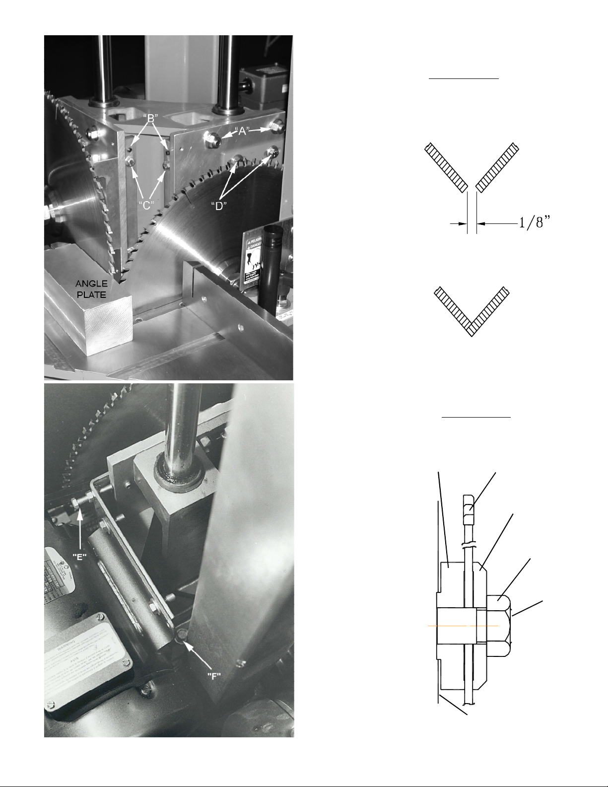
3. Replace flange and nut as before, and tighten (refer to Diagram No. “2” on Page No. 5).
4. If blades were purchased from CTD, your machine has been set with your blades marked “RIGHT” and
“LEFT” for Notching. If not, diameters vary. Follow special Instructions for Aligning Blades below. See
Diagram No. “1” on Page No. 5 for blade configuration. If notching, right blade must be directly below
left blade. If mitering, blades are set on the same plane and should be set for Miter Configuration (see page 5)
The blade must rotate down and to the rear of the machine on the underside of the blade (see Picture “A” on Page
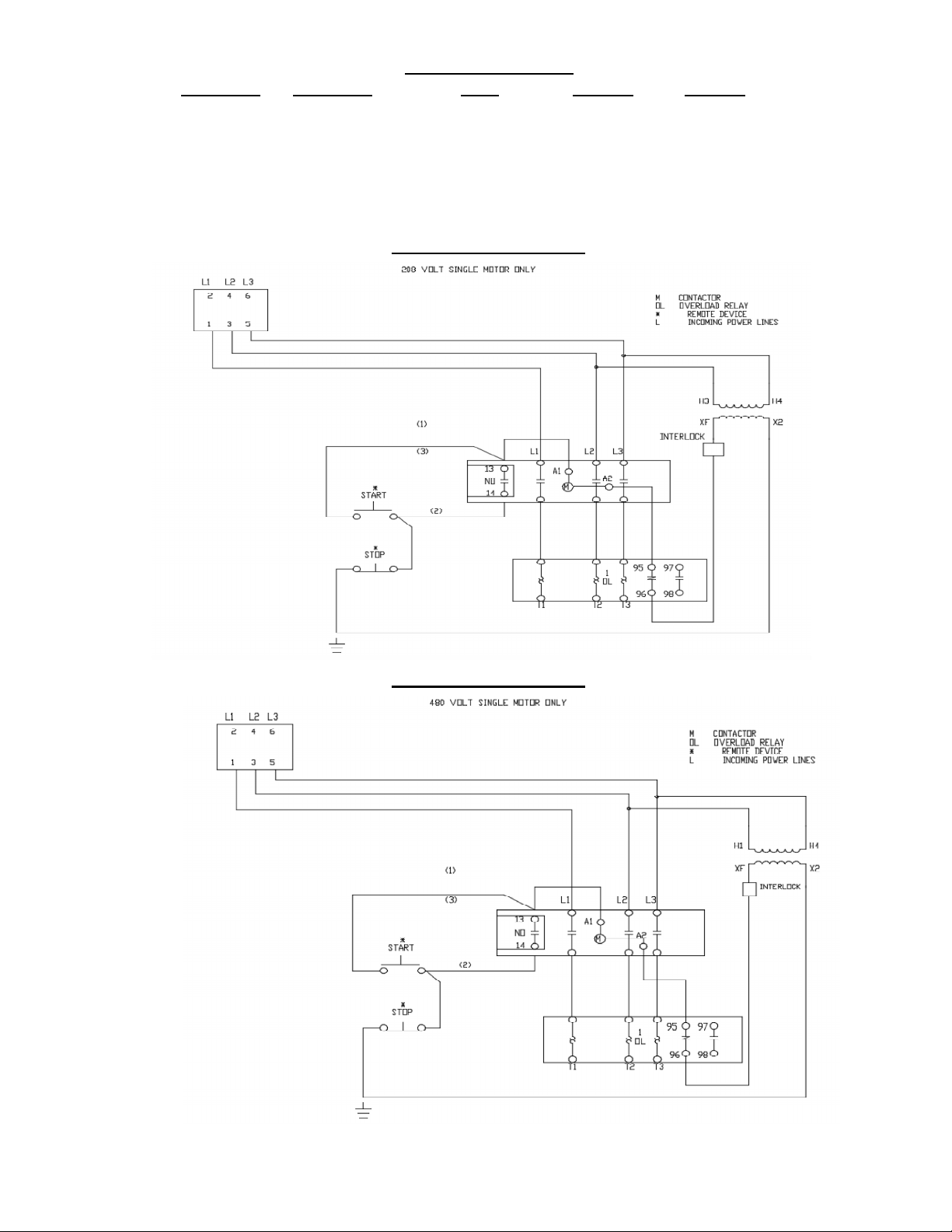
No. 5). Your machine has been wired for the specified voltage at the time of your order. Note: You cannot change
the voltage without changing the starter. The motors have been connected to the starter.
Instructions for Aligning Blades on Model N90X:
Using an angle plate and the left blade as a reference point, touch the angle plate to the outside carbide tips of the blade.
Be sure the angle plate is square to the tips and not touching the plate of the blade. The tip of the right blade should
make very slight contact with the edge of the angle plate when rotated in the opposite direction (by hand) for
the notching configuration. For Mitre Configuration, set blades as shown in Diagram No. 1
1.To move blade forward (see Pictures “A” & “B”):
A. Loosen bolt “F” on the Motor Mount Bottom Angle, P/N 9M26 R or L (see Picture “B”, bottom rear of Slide).
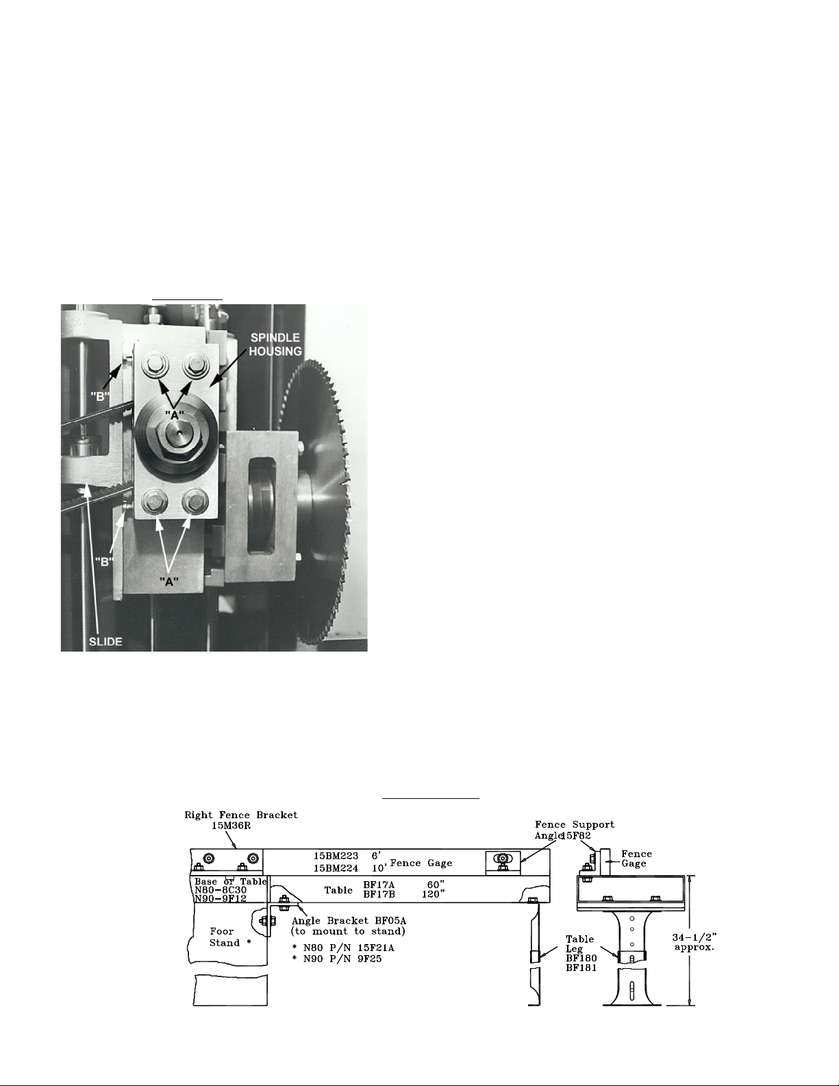
B. Loosen and lightly snug four lock bolts marked “A” Top & Bottom located on P/N 9M28 R or L Spindle
Housing Mounting Plate. **Be careful not to loosen too much, as this will cause the mounting plate to cock
at an angle.
C. Loosen bolts “C”, top and bottom (4), located on Blade Adjustment Bar, P/N 9M38.
D. Loosen nuts only on bolts “B”,(4) top and bottom, located on Blade Adjustment Bar, P/N 9M38. Turn bolts
“B” to the right to move blade forward.
1. If blade is positioned correctly for Notching, when it is rotated by hand backwards, blade should make a
slight ticking sound against angle plate.
E. After blade has been adjusted;
1. Tighten nuts on bolts “B”, top and bottom (4)
2. Snug bolts “C”, top and bottom (4)
3. Firmly tighten four lock bolts “A”, top and bottom
4. Tighten bolt “F” on Motor Mount Angle, P/N 9M26 R or L
2. To move one blade backwards (see Pictures “A” & “B”)
A. Loosen bolt “F” on Motor Mount Angle, P/N 9M26 R or L (see Picture “B”, bottom rear of Slide).
B. Loosen and lightly snug four lock bolts marked “A” Top & Bottom (4) located on P/N 9M28 R or L Spindle
Housing Mounting Plate. **Be careful not to loosen too much, as this will cause the mounting plate to cock
at an angle.
C. Loosen nuts and bolts “B”, top and bottom (4), located on Blade Adjustment Bar, P/N 9M38
D. Turn bolts “C”, top and bottom (4) to the right and tighten to move blade backward.
1. If blade is positioned correctly for Notching, when it is rotated by hand backwards, it should make a slight
ticking sound against the angle plate.
E. After blade is adjusted
1. Snug bolts “B” (4) and tighten nuts
2. Firmly tighten four lock bolts “A”, top and bottom
3. Tighten bolt “F” on Motor Mount Angle, P/N 9M26 R or L
-4-