)
Illustrations
1.1
8500™
Compressor
. . . . • . . • . . • . • • .
1-4
3.1
Block
diagram
for
8500
Compressor
installation.
. • • . • . . . . . . •
3-1
3.2
Removing
compressor
pump
shipping
supports
. , , , , , , , , , , , , , , ,
3-2
3.3
Stripping
compressor
input-power
cable
insulation
. , , , , ,
..
, , , , , , , , ,
3-2
3.4
Input
power
cable
receptacle
plug
• • . . . • . • . . . • • • . • •
3-3
3.5
Wiring
diagram
for
compressor-
receptacle
plug.
. • . • . . • . . . . . • • . • .
3-3
3.6
Preparing
the
8500
Compressor
control
module
••..•.•..•.
3-5
3.7
8500
Compressor
installation
....•.••
, • . • • . . • . • • .
3-7
4.1
Disconnecting
the
adsorber
self-sealing
couplings
••
, , . . • . , , . . . .
4-1
4.2
Connecting
self-sealing
couplings
• , , , . . •
4-2
B.l Electrical
schematic
for
8500
Compressor,
P/N
8031351.
••.•.••.•..
B-3
C.
l
Components
in
the
electrical
control
module
of
8500
Compressor.
,
.••••..•.
C-3
D.
l
Flow
diagram
of
8500
Compressor
. . . • . . . . • . . . . . • . • . .
D-1
E.
l
Typical
multiple
cryopump
installation
with
8500
Compressor
• . . . • . . . . . . • •
E-1
F.
l
Remote
high-vacuum
pump
switching
schematic.
. . . . . . . • . • . • . .
F-2
v/vi
CTI-CRYOGENICS
HEifX--fEcHNOLciGY"
·c-OR"PORATJON
Tables
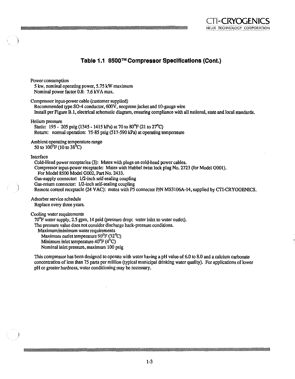
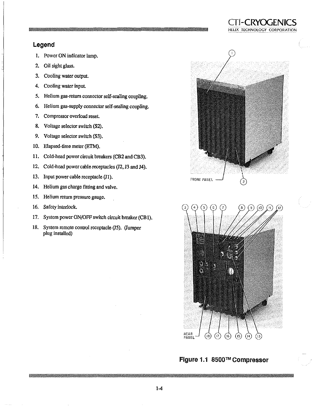
1.1
8500™
Compressor
Specifications. , , , , , ,
1-2
A.
l
Compressor
Troubleshooting
Procedures
•.....•.•.••.•..•...
A-2