RV BLIND SPOT DETECTION SYSTEM: For Motorhomes | 5
English Operation Guide
7. OPERATION
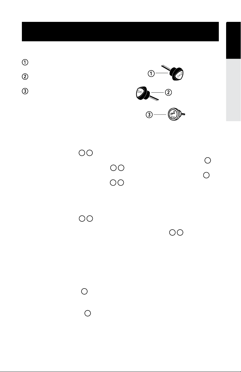
Indicator
Left Side Blind Spot Indicator
Right Side Blind Spot Indicator
POWER button
System Power
1. The system will automatically activate when the ignition is turned on.The warning
indicator lamps illuminate for 3 seconds during startup.
2. The system may be deactivated by pressing and holding the POWER button for
3 seconds, the indicator lamps will blink twice to conrm.
3. The system may be reactivated by pressing and holding the POWER button for
3 seconds, the indicator lamps will illuminate for 3 seconds to conrm.
System Activation
1. Start vehicle.
2. Indicator lamps will illuminate for 3 seconds to conrm activation and run
self-diagnostics.
3. If there are errors, the system will ash the indicator lamps and sound
tones to indicate the problems. Please use the TROUBLESHOOTING section for
more help.
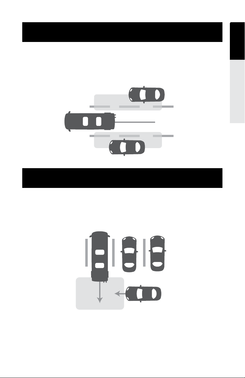
4. The Blind Spot Detection System will turn on when you start the engine and begin
driving forward above approximately 12mph.
Blind Spot Indicator Lamps
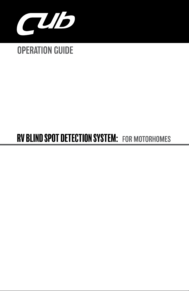
1. The left indicator will illuminate when a vehicle is in your left blind spot while
driving. This indicator will ash and an audible tone will sound when your left turn
signal is activated while there is a vehicle in the left blind spot.
2. The right indicator will illuminate when a vehicle is in your right blind spot
while driving. This indicator will ash and an audible tone will sound when your
right turn signal is activated while there is a vehicle in the right blind spot.
1
2
1 2
1 2
1 2
3
3
1 2
1 2