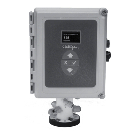
Culligan Smart Controller (GBE) Manual

CULLIGAN®
Smart Controller (GBE)
For Commercial and Industrial Softener
and Filter Applications
Models from 2011
Firmware Version 2.1.3
©2011 Culligan International Com pa ny
Installation,
Operation, and
Service Instructions
with Parts Lists
Printed in USA
Cat. No. 01021161
Rev. H 01/10/11
DCO # 012139

Attention Culligan Customer:
Your local independently operated Culligan dealer employs trained service and maintenance personnel who are experienced
in the installation, function and repair of Culligan equipment. This publication is written specifically for these individuals and is
intended for their use.
We encourage Culligan users to learn about Culligan products, but we believe that product knowledge is best obtained by
consulting with your Culligan dealer. Untrained individuals who use this manual assume the risk of any resulting property
damage or personal injury.
WARNING! Electrical shock hazard! Prior to servicing equipment, disconnect power supply to prevent
electrical shock.
WARNING! If incorrectly installed, operated, or maintained, this product can cause severe injury.
Those who install, operate, or maintain this product should be trained in its proper use,
warned of its dangers, and should read the entire manual before attempting to install,
operate, or maintain this product. Failure to comply with any warning or caution that
results in any damage will void the warranty.
CAUTION! This product is not to be used by children or persons with reduced physical, sensory or
mental capabilities, or lack of experience or knowledge, unless they have been given
supervision or instruction.
CAUTION! Children should be instructed not to play with this appliance.
CAUTION! If the power cord from the transformer to the unit looks or becomes damaged, the cord
and transformer should be replaced by a Culligan Service Agent or similarly qualified
person in order to avoid a hazard.
WARNING! This device complies with Part 15 of the FCC rules subject to the two following conditions:
1) This device may not cause harmful interference, and 2) This device must accept all
interference received, including interference that may cause undesired operation.
This equipment complies with Part 15 of the FCC rules. Any changes or modifications not expressly approved by the
manufacturer could void the user’s authority to operate the equipment. Changes or modifications not expressly approved by
the party responsible for compliance could void the user’s authority to operate the equipment.
CAUTION! To reduce the risk of fire, use only No. 26 AWG or larger telecommunications line cord.
NOTE This system is not intended for use with water that is microbiologically unsafe or of unknown quality.
NOTE Check with your public works department for applicable local plumbing and sanitation codes. Follow local
codes if they differ from the standards used in this manual. To ensure proper and efficient operation of the
Culligan equipment to your full satisfaction, carefully follow the instructions in this manual.
Products manufactured and marketed by Culligan International Company (Culligan) and its affiliates are protected by patents
issued or pending in the United States and other countries. Culligan reserves the right to change the specifications referred to
in this literature at any time without prior notice. Culligan, Aqua-Sensor, Tripl-Hull, and SoftMinder are trademarks of Culligan
International Company or its affiliates.
Culligan International Company
9399 West Higgins Road, Suite 1100
Rosemont, Illinois 60018
1-847-430-2800
www.culligan.com

Contents i
Cat. No. 01021161
Installation,
Operation,
and Service
Instructions with
Parts List
Culligan® Smart Controller (GBE)
For Commercial and Industrial Softener
and Filter Applications
Models from 2011
Firmware Version 2.1.3
Contents
Introduction ........................................................................ 1
Smart Controller Features ................................................. 2
Basic Principles ................................................................. 4
Operation ........................................................................... 5
Installation ......................................................................... 6
Smart Controller Circuit Board Layout ............................. 10
Smart Controller Programming ........................................ 14
Navigating the Menus and Keypad.................................. 15
First Time Set Up ............................................................. 19
Customizing Set Up ......................................................... 22
Softener and Filter Program Log ..................................... 29
Installing Accessories ...................................................... 30
Service and Maintenance ................................................ 69
Manual Regeneration ...................................................... 71
Manual Cycling ................................................................ 72
Error and Alert Codes ...................................................... 73
Diagnostic Screens.......................................................... 75
Menu Overview................................................................ 82
Smart Controller (GBE) Parts and Accessories ............... 86
Appendix A Programming Examples............................. 87
Appendix B Data Port Output........................................ 92
Appendix C Flow Device K-Factor Data .......................... 97
Culligan® Softener and Filter Program Log .................... 98
Index ............................................................................... 99

ii Culligan® Smart Controller (GBE) for Softeners and Filters ii Cat. No. 01021161
Document Change History
DCO Chapter Description Reason
012139 Programming Updated menu selections and structure FWR 2.1.3

Introduction 1
Cat. No. 01021161
Introduction
Read this Manual First
Before you operate the Culligan Smart Controller (GBE), read this manual to become familiar with the device and
its capabilities.
About this Manual
This manual:
• Familiarizes the operator with the equipment
• Explains installation and setup procedures
• Provides basic programming information
• Explains the various modes of operation
• Gives specifications and troubleshooting information
Safe Practices
Throughout this manual there are paragraphs set off by special headings.
Notice
Notice is used to emphasize installation, operation or maintenance information which is important, but does not present
any hazard. For example,
NOTICE The nipple must extend no more than 1 inch above the cover plate.
Caution
Caution is used when failure to follow directions could result in damage to equipment or property. For example,
CAUTION! Disassembly while under water pressure can result in flooding.
Warning
Warning is used to indicate a hazard which could cause injury or death if ignored. For example,
WARNING! Electrical shock hazard! Unplug the unit before removing the timer mechanism or
cover plates!
The CAUTION and WARNING paragraphs are not meant to cover all possible conditions and situations that may occur. It
must be understood that common sense, caution, and careful attention are conditions which cannot be built into the equip-
ment. These MUST be supplied by the personnel installing, operating, or maintaining the system.
Be sure to check and follow the applicable plumbing codes and ordinances when installing this equipment. Local codes
may prohibit the discharge of sanitizing or descaling solutions to drain.
Use protective clothing and proper face or eye protection equipment when handling chemicals or power tools.
NOTE The Culligan Smart Controller (GBE) is not intended for use with water that is microbiologically unsafe
or of unknown quality without adequate disinfection either before or after the system.
NOTE Check with your public works department for applicable local plumbing and sanitation codes. Follow
local codes if they differ from the standards used in this manual. To ensure proper and efficient
operation of the Culligan Smart Controller (GBE) to your full satisfaction, carefully follow the instruc-
tions in this manual.

2 Culligan® Smart Controller (GBE) for Softeners and Filters 2 Cat. No. 01021161
Smart Controller Features
The primary function of the Culligan Smart Controller (GBE) is to initiate and control the regeneration process via methods
that are most convenient and cost effective for the customer while offering many operational features and benefits. The
controller is designed to operate a wide range of existing and new softener and filtration valves.
Take Control of Your System and Your Productivity
The Culligan Smart Controller (GBE) is an advanced design engineered to handle regeneration and monitoring of your
water treatment equipment. It offers powerful programming options that can be used to operate and monitor any softener
or filter system. It also provides sensing capabilities, expanded communications and a multifunction keypad—all in one
simple-to-use unit.
Smart Controller Features
Feature Use/Benefit
Advanced Lighted OLED Display The user is guided through brightly lit graphical menu screens with clear,
multi-line, full text prompts. See Figure 1.
Membrane Keypad The keypad uses sealed contacts for programming. No buttons to get dirty.
See Figure 1.
Program Beeper Emits an audible beep when keys are depressed to help identify valid (short
beep) or invalid (three short beeps) pushes. Can be enabled or disabled.
Power Source Electrical power required is 24 Volt 50/60 Hz AC current. A UL listed plug-
in transformer (120V/24V) is provided.
Time of Day Displays current time of day in either 12-hour or 24-hour format.
Real Time Clock with a Five-Year Battery
Back-up
Keeps accurate time even during a power outage. Updates automatically
when the GBE is equipped with optional modem capability.
English or Metric Values Displays can be set to either English or Metric units.
Regeneration Interval Provides the ability to initiate a time clock regeneration based on a number
of days (1–99) or a specific day of the week.
Regeneration Start Delay Allows a user determined number of hours (0-9) to be set for the purpose
of increasing the amount of time between regenerations in a multi unit
installation.
Auxiliary Input Capable of accepting a remote signal from a dry contact device such as an
operator push button for the purpose of initiating a regeneration sequence
or external alarm signal.
Auxiliary Output on Alarm Capable of sending a signal when an alarm/error is recognized.
Figure 1. Smart Controller.
Figure 2. Remote display.

Smart Controller Features 3
Cat. No. 01021161
Feature Use/Benefit
Expansion Board for Additional Outputs • Control blocking valves.
• Control external solenoids or chemical feeders.
Progressive Flow Trip Point and
Unbalanced Progressive Flow
Allows multiple tank systems operating with flow meters to bring tanks on-
line or off-line as facility flow demands increase or decrease.
Multiple Unit Communication A communication cable interconnects multiple units to operate the controller
in the Progressive Flow mode and prohibits them from regenerating at the
same time.
Diagnostics The user can check the operation of sensors, progressive flow communica-
tion, motor positions, or an optional wireless display.
Transformer is UL and CUL Listed
RoHS Compliant
Optional Smart Controller Features
Feature Use/Benefit
Flow Meter/Sensor Input Supports various types of Hall effect flow sensors using a pro-
grammable K factor to initiate a regeneration sequence.
Aqua-Sensor® Input Supports the patented digital Culligan Aqua-Sensor® technology
used to efficiently initiate and control a regeneration sequence.
Telephone Modem • Calls in reports on regenerations and alarm conditions.
• Automatically updates time and date when calling in.
Wireless Remote Display Displays the current status of the unit. It can be located up to 200
feet away from the GBE controller (depending on building and in-
terference). The telephone modem can optionally be installed in
the remote display. See Figure 2.
Smart Brine Tank Probe This probe monitors conditions inside the brine tank.
• Predicts when more salt is needed.
• Detects the presence of a salt bridge.
• Detects eductor line plugging.
• Signals brine tank overfilling condition.

4 Culligan® Smart Controller (GBE) for Softeners and Filters 4 Cat. No. 01021161
Basic Principles
What Is Hard Water?
Water is said to be hard when it carries too high a concentration of calcium and magnesium. Acceptable water hardness
levels will vary depending on the application.
Why Should Hardness Be Removed?
Hard water causes scaling and etching which greatly impairs the life and efficiency of boilers, air-conditioning systems,
cooling towers, water heaters, refrigeration plants and other equipment using water.
How Does It Work?
The components of dissolved minerals are called ions. They carry either a positive or negative charge. Hardness ions of
minerals dissolved in water carry a positive charge. These positively charged ions (cations) are attracted to a synthetic
softening material called ion exchange resin.
The heart of the softening system, therefore, is a deep bed of resin which draws calcium and magnesium ions, as well as
ferrous iron, from the water as it passes through the resin bed.
Can The Resin Draw Out Hardness Ions Indefinitely?
No. During normal operation, the resin becomes saturated with positive ions and functions less efficiently. When hardness
leakage occurs, the resin should be regenerated to restore its efficiency.
How Do You Regenerate Resin?
You regenerate a resin bed by removing the mineral ions through a process called ion exchange. This regeneration pro-
cess occurs in four steps and takes approximately 80 to 90 minutes.
Backwash
During the backwash step, raw water flows rapidly upward (in reverse direction to the service flow) through the resin bed
to expand the bed and flush out accumulated dirt, sediment and other sources of turbidity.
Brine Draw
The brine solution consisting of water and salt is drawn from a brine storage tank and allowed to flow slowly down through
the resin bed. The brine solution removes the calcium and magnesium ions from the resin. This cycle can also be split into
three “sub-cycles” which allow for the cost saving feature of brine reclaim.
Slow Rinse
Brine draw is then followed by a raw water slow rinse. This rinse step will slowly remove most of the remaining brine,
exchanged calcium and magnesium ions from the resin. This cycle can also be split into three “sub-titles” which allow for
the cost saving feature of brine reclaim.
Fast Rinse
Slow rinse is followed by a raw water flush, a very rapid down flow of raw water which removes the last traces of brine,
and settles the resin bed.
How Often Must You Regenerate?
Frequency must be determined for each installation based on the amount of water usage, its degree of hardness and the
amount of resin through which it flows. In some cases it is necessary to utilize a resin cleaner when the raw water con-
tains iron. Contact your local Culligan dealer for more information.
How Do You Control The Regeneration Process?
The regeneration process for your commercial water softener is controlled automatically either on a predetermined time,
volume, or external signal basis through the use of the Culligan GBE controller with optional flow sensor. See the Installa-
tion chapter for further information. The regeneration process can also be initiated manually by the operator as required.

Operation 5
Cat. No. 01021161
Operation
Modes of Operation
Time Clock
The Smart Controller (GBE) will initiate a regeneration based upon a time schedule of intervals of days (such as every
three days) or on a specific day of week schedule (such as Mondays, Wednesdays and Saturdays). Because regenera-
tion will occur at the prescribed schedule regardless of water use, this method is usually the most inefficient method of
water softener operation.
Flow Meter/Sensor
When a flow meter or sensor is connected to the controller circuit board, the Smart Controller has the ability to measure
the amount of water treated and initiate a regeneration sequence based upon the gallon capacity of the water treatment
equipment. The controller can delay the regeneration signal until a convenient time of day (known as a delayed regenera-
tion) or act and initiate the regeneration sequence as soon as the signal is received (known as immediate regeneration).
When installing an alternating duplex system (one tank on-line, the other in standby), only one flow measuring device is
required to be installed in the common outlet header of the system. Parallel systems (multiple tank systems, all on-line
simultaneously) require one flow device for each mineral tank in the system.
This method is a proven, cost-effective means to operate a water softening system.
Aqua-Sensor® (Softener use only)
The Aqua-Sensor® detects when a softener resin bed has reached its point of exhaustion and, as a result, initiate a regen-
eration sequence. This is the most cost-effective method of operation and may be combined with any of the operational
modes previously described.
Progressive Flow
The Progressive Flow mode is used with up to six and as few as two mineral tanks in a system. It allows more than one
tank in a system to either be on-line or off-line depending upon the downstream flow demand. If flow demand is greater
than the flow capability of the tank on-line, another tank can be brought on-line to help satisfy the excess demand. Once
the demand has decreased, the second tank is returned to a standby mode and the system reverts to just one tank on-line
providing treated water.
The progressive flow mode of operation relies on a user programmable set point or Trip Point. The Trip Point is a unit of
flow (gallons or liters) on a per minute basis. Once attained the trip point will cause the second unit (in multiple resin tank
system) to come on-line. Each additional tank in the system will subsequently be brought on-line as multiples of the trip
point are attained and remain in that state for ten seconds. (Example: a three-tank system with a trip point of 50 gpm will
bring two tanks on-line once the facility flow demands is equal to or greater than the 50 gpm trip point. Should the flow
demand reach 100 gpm or more, the third tank shall be brought on-line.)
Additional tanks will be returned to stand-by once the facility flow demand is: less than 95 percent of the trip point for two
tank systems; less than 95 percent of two times (2X) the trip point for triplex systems; less than 95 percent of three times
(3X) the trip point for quad systems; and remaining in that state for 30 seconds.
Utilizing the progressive flow feature may allow the owner to use smaller units, resulting in the potential for reduced capital
and operation costs.
Unbalanced Progressive Flow
Similar to regular Progressive Flow, this mode is used when maximum and minimum flow rates have a wide fluctuation.
In this mode you can have one tank that is smaller than the others. This tank has a separate Trip Point set so the Smart
Controller knows what flow rate it can run at. The additional larger tanks are brought on-line when the trip point of the
smaller tank is exceeded. The small tank is only online during low flow conditions. The small tank must be set up as the
master tank.
Differential Pressure (Filters Only)
When combined with an optional differential pressure device, the Culligan Smart Controller has the ability to initiate a
backwashing sequence when the pressure differential across the media bed reaches a preset amount (usually 8–10 psi).

6 Culligan® Smart Controller (GBE) for Softeners and Filters 6 Cat. No. 01021161
Installation
Electrical Installation
CAUTION! Observe the precautions listed below before electrical installation of your Smart
Controller (GBE). Failure to do so may cause permanent damage to the controller.
• Follow the local electrical code requirements.
• Be sure electrical power is off and disconnected at the source before completing any wiring/cabling connections.
• Provide a dedicated 120 Volt circuit for the Smart Controller system to ensure maximum electrical protection.
• DO NOT include the Smart Controller wiring cables in any conduit or raceway containing other 120 Volt or higher
circuits.
• Maintain a distance of at least 10 feet between the Smart Controller and any electrical distribution panels, race-
ways carrying 300 Volts or more, and electrical motors of 1 horsepower or more.
• Use the cabling provided. Failure to do so may effect performance of the Smart Controller adversely.
WARNING! One transformer is required for each controller in the system. Do not attempt to operate
multiple controllers without a dedicated transformer for each or your system will experi-
ence operational difficulties.

Installation 7
Cat. No. 01021161
Wiring Procedures and Diagrams
Preparation
1. Loosen the screws or latches securing the controller access cover (see Figures 3 or 4) on each controller
provided.
Figure 3.
Figure 4.
Figure 5.

8 Culligan® Smart Controller (GBE) for Softeners and Filters 8 Cat. No. 01021161
Cable Routing
All input and output connections to the circuit board are 24 Volt or less.
Although the cables do not have to be run in conduit, it is necessary that long runs of cable be supported or protected by
strapping them to the equipment piping. If conduit will be used to route the shielded cables, three factors must be consid-
ered:
1. DO NOT share the same conduit or raceway with 120 Volt or higher circuits.
2. Keep cables at least six (6) inches away from 120 Volt or higher electrical circuits.
3. GROUND the conduit (if metallic) to a known “earth ground” location.
A series of holes are located on the sides of the Smart Controller (see Figures 6 and 7). Strain relief fittings are provided
with the controller enclosure for interconnecting wiring. Install the plastic fittings as needed. Remove the compression nut
and rubber sleeve from each fitting. Prior to connection of the cable wires to the circuit board, slide the compression nut
and sleeve over the cable for the wiring connections. When wiring is completed, apply a small amount of silicone to the
rubber sleeve and reassemble. This will assure all wiring is secure and assist in making the tightening of the fitting easier.
Insert the plugs provided to block any holes not used for wiring or other accessories.
Right Side View
Brine Reclaim Solenoid
(optional)
Input Connection
for Flow Sensor
Output Connection
for Remote
Accessories
Input Connection
for Remote
Accessories
24 Volt Power
Input Connection
Brine Reclaim Solenoid
(optional)
Figure 6. Brine Refill Valve
Blocking Solenoid for
Alternating Operation
Left Side View
Figure 7.

Installation 9
Cat. No. 01021161
Smart Controller Overview
To access the inside of the Smart Controller, refer to the instructions below.
CAUTION! Failure to complete the following steps might
result in damage to the keypad or circuit
board!
1. Loosen the front cover screw.
2. Hinge the front cover upwards. (See Figure 8). Do not remove the
front cover yet.
3. Disconnect the keypad from the circuit board.
4. Remove the front cover.
CAUTION! Grip all connections to the circuit board by
connecting terminals for assembly and disas-
sembly. Failure to do so could result in dam-
age to the wire leads or connecting terminals.
CAUTION! Do not touch any surfaces of the circuit board. Electrical static discharges may cause
damage to the board. Handle the Smart Controller circuit board by holding only the
edges of the circuit board. Keep replacement boards in their special anti-static bags
until ready for use. Mishandling the circuit board will void the warranty.
5. The circuit board is held on with plastic posts. Push the locking clip at the end of the posts to allow the circuit
board to be removed from the daughter board.
GBE CIRCUIT BOARD
AUXILIARY CIRCUIT BOARD
CIRCUIT BOARD BRACKET
INTERFACE CIRCUIT BOARD
Figure 9. Locking clip.
CAUTION! Properly connect the wire connectors to the circuit board. The wires must exit the plug-
in connector opposite of the raised white base of the circuit board connector.
CAUTION! Take extra care when connecting the 2.5 VAC and 24 VAC power. Failure to connect
properly will result in damage to the circuit board.
Figure 8. Circuit board.

10 Culligan® Smart Controller (GBE) for Softeners and Filters 10 Cat. No. 01021161
Smart Controller Circuit Board Layout
Smart Controller Circuit Board Layout–Front
Figure 10. Smart Controller circuit board layout, front view.
Smart Controller Circuit Board Layout–Back
Aqua-Sensor
Cable (Optional)
Power Cable
(from transformer)
Optional
Alarm Relay Board
Connection (Aux 5)
Optional Modem
Connections
Data Port
PLC Output
RF Board
Connection
(for remote)
Future Use
Do Not Connect
Anything to these
Communication Cable
(optional)
Motor Position Cable
Multiple Unit Jumper
Flow Meter Cable
(optional)
Smart Brine Tank
Cable (optional)
External regeneration
signal connection (optional)
or external alarm Motor
Connection
Blocking Valve
Connection (optional)
Programmable
Outputs
(optional)
POSITION DC
MOTOR
FLOW
METER
RS485
BRINE
TANK
J22
2.5v 24v
AQUA SENSOR
AUX OUT4
AUX OUT3
AUX OUT2
AUX OUT1AUX INPUT
Figure 11. Smart Controller circuit board layout, rear view.
Keypad connector
Battery
CR2032 (Postitive Side Up)
Pull protective tab before activating
power to activate the battery
OLED Display

Smart Controller Circuit Board Layout 11
Cat. No. 01021161
Smart Controller Circuit Board Outputs
The circuit board supports four outputs:
• Motor control (DC Motor)
• Blocking valve (Use Aux Out 4)
• Two programmable auxiliary outputs (Aux Out 2 and Aux Out 3) for commercial four-cycle and five-cycle valves.
• Controller interface (communication between multiple controllers) (RS485).
CAUTION! Connecting 24 V to the 2.5 V connection on the circuit board will damage the circuit
board.
NOTE If you are using Aqua-Sensor®, you should run the 2.5 V wiring now as the cable is run through the
same cord grip. See page 12 for details.
Wiring the Smart Controller Power Cord
1. Locate the power cord among the controller parts. It has a white connector on one end and two spade connec-
tors on the other.
2. Locate the cord grip among the parts.
3. To assemble the power cord, first run the cord grip nut over the spade terminal end of the power cord.
4. Next, run the spade terminals through a hole in the side of the controller FROM THE INSIDE (see Figure 12).
5. Finally, run the cable through the bottom end of the cord grip, and assemble the grip to the controller wall.
6. Plug the board connector to the board where it is labeled 24 V. The connector has four (4) connections but only
two wires are connected. The other end of the power cord (with spade terminals) should be connected to the
two 24 VAC terminals on the transformer (see Figure 13).
CAUTION! DO NOT PLUG THE TRANSFORMER INTO THE WALL UNTIL ALL WIRING IS
COMPLETED.
7. Repeat the process for any additional units in the system.
METAL TABS
Connect to white connector
on main power cord
If using Aqua-Sensor,
plug metal tabs at end
of cord into connector
Figure 12. 24 V Power Connection

12 Culligan® Smart Controller (GBE) for Softeners and Filters 12 Cat. No. 01021161
24 V Transformer
The Smart Controller is powered by a 24 VAC/100 VA transformer. If there are multiple controls in the system being
installed, each controller will require its own transformer. It is recommended that the transformer be plugged into a
dedicated 120V circuit.
CAUTION! Connecting 24 V to the 2.5 V connection on the circuit board will damage the circuit
board.
CAUTION! To eliminate the possibility of polarity issues, carefully follow the wiring details shown
in Figure 13.
1. Connect one wire from the 24 V cable to the outermost 24 VAC transformer screw terminal (see Figure 13). The
other end of the wire should be connected to one of the 24 V terminals on the Smart Controller circuit board
(Figure 13) by way of the white connector.
2. Repeat the process for the other 24 V power supply wire attaching the second wire to the opposite terminal on
the transformer and next to the other wire connected to the 24V pins on the Smart Controller board.
Figure 13. Transformer and Smart Controller circuit board.

Smart Controller Circuit Board Layout 13
Cat. No. 01021161
Brine Refill Valve Wiring
NOTE This only applies to Culligan CSM Softeners.
Install the Solenoid Coil and Connector
1. Locate the solenoid coil and connector cord.
2. Assemble it to the brine refill valve as shown in Figure 14.
Install the Cord Grip
1. Remove the hole plug from the left side of the Smart
Controller enclosure.
2. Locate the cord grip fitting and nut.
3. Assemble them through the open hole and thread the
solenoid coil cord through the cord grip fitting as shown
in Figure 15.
4. Tighten the cord grip onto the cord.
Wire the Valve
1. Wire the valve to Aux Out 2 as shown in the diagram
in Figure 16.
2. Trim the wires to a suitable length.
NOTE Remember to set the brine refill time when using
the brine refill valve. It is set using Aux2. See
page 47 for programming instructions.
Solenoid
Coil
Screw Plastic
Spacer
Figure 14.
Figure 15.
Figure 16.
2.5VAC
P9 Power
24VAC
Vlv
Aux1
Sol
P7 Aux2
P8P5
Cam
P1 P10
Snsr
Aqua Meter
P4
Flow In
P2
Aux
LCD
TRIM OFF
GREEN WIRE
BLACK
WHITE
REFILL
SOLENOID
VALVE
CIRCUIT BOARD
MVP

14 Culligan® Smart Controller (GBE) for Softeners and Filters 14 Cat. No. 01021161
Smart Controller Programming
Programming
The programming process requires various types of data input. The following information pertains to calculating the soft-
ening capacity of the water softening system.
Capacity Settings
The capacity of a water softener is determined by two factors; resin amount and water chemistry.
Single Tank Systems
Normally a single tank system has enough resin capacity to soften water for a minimum period of 24 hours. Time of regen-
eration is usually set to occur very early in the morning or at a time when no softened water is required. This is because
when the softener is regenerating, hard water is typically bypassed through the system and into the facility if a demand for
water if present.
If regeneration is desired at a time of day when there is no water usage then the system must have a “reserve” capacity
which must last an entire day if the regeneration signal (time clock, Aqua-Sensor® and/or meter) occurs at the beginning
of the day. Subtract this reserve capacity from the total capacity to determine capacity to signal.
NOTE If the reserve capacity is more than one-third (1/3) of the total capacity, a meter system may not reduce
salt consumption relative to a timeclock system.
Multiple Tank Systems
Multiple tank systems offer the benefit of continuous soft water supply. When using the Aqua-Sensor® to initiate a regen-
eration sequence, the system capacity may be set for the maximum amount the system is capable of producing. However
multiple tank systems using only water meters and or time clock as the basis for regeneration initiation are recommended
to be set up with a 10% reserve capacity. The purpose of the reserve capacity in multiple tank systems is to allow for
subtle changes in water chemistry. You will be able to get the reserve capacity during programming.
Determining Batch Set Point
To determine the batch set point for programming the Culligan Smart Controller, use the following formula:
Total Capacity – Reserve Capacity
Hardness
= Gallons
The Smart Controller will calculate this for you automatically. You can use the formula above to verify the setting.
For more information on programming multi-tank systems, see page 39.
Program Data Input
There are a few items to note that can make the programming of the Smart Controller a little easier. They are:
Slew Rates This term refers to the speed at which the display moves through the input of mate-
rial. For example, holding down the up arrow key for five (5) seconds when inputting
minutes for Time of Day will cause the minutes to pass in ten (10) minute blocks of
time. Press the up arrow or down arrow keys for shorter periods (less than 5 seconds)
will slow the rate. To move through the programming slowly, do not hold down the up
arrow or the down arrow keys.
Beeper A beeper is available to assist the user by providing an audible tone (about 70 deci-
bels) to signify valid (one beep) and invalid (three beeps) key presses. The beeper
can be deactivated in the programming mode. (If error occurs, beep will still be ON
even if set to “No” programming.)
Programming Mode Timeout If there is no keypad activity for a three (3) minute period while in the programming
mode, the controller will exit the programming mode and return to the main display.
Any setting that was changed prior to the control timing out will revert back the origi-
nal value. Pressing the check mark key saves the setting.
Program Input Acceptance For programming information to be accepted, the check mark key must be depressed
prior to programming mode timeout.

Navigating the Menus and Keypad 15
Cat. No. 01021161
Navigating the Menus and Keypad
DOWN button
CHECK MARK or
OK button
UP button
CANCEL (X) button
UP ARROW button: scrolls up the menu
Controller
Remote
DOWN ARROW button: scrolls down the
menu
CHECK MARK button: selects the highlight-
ed option, opens a new screen, or accepts a
changed setting
CANCEL or EXIT button: returns to the pre-
vious screen or cancels a changed setting
NOTE Hold down the or button to quickly scroll through the setting without repeatedly pressing
the button.
1. This is the home screen. Press any key except to display the main menu.
2. This is the main menu. The cursor/pointer (>) shows where you are in the menu.
Use or to scroll through the menu. The selection cursor scrolls down to the
next line or displays the next screen.
3. Press to select the item next to the cursor. For example, press to
select 3)SET DATE/TIME.

16 Culligan® Smart Controller (GBE) for Softeners and Filters 16 Cat. No. 01021161
4. The controller screen displays a setting title and value. Here we see the current
value for the month setting is January.
5. Press to select the item. The screen displays a cursor next to the value. This
indicates that the value may be changed by pressing the or button.
6. Press to select a new value. The screen displays the new setting value next to
the cursor.
7. Press to select the next available value. You may press or to scroll
through all available options for this setting.
8. Press to accept the selected screen value. The screen displays the value, no
longer preceded by the cursor.
9. Press to scroll to the next setting.
10. Press to exit from the setting without saving changes. The screen displays the
parent menu (such as the main menu).
11. Press to display the home screen.
NOTE Unplugging the Culligan water softener will not affect any of the control settings (the control must be
plugged in for at least 15 minutes). Once programmed, the settings will be stored indefinitely.
Table of contents
Other Culligan Controllers manuals
Popular Controllers manuals by other brands

Viconics
Viconics VT7225 series User Interface Guide

ADC
ADC AD-320 installation manual

gefran
gefran GPC 40-600A Use and installation manual

Blueprint Controllers
Blueprint Controllers BDAC-1 instructions

Mitsubishi Electric
Mitsubishi Electric Q172CPU Programming manual

Zennio
Zennio MINiBOX 25 Technical documentation