Cumberland Evolution 4000 User manual

Part No. 4801-5338 Rev 2-2015 Owners Manual Evolution 4000
CUMBERLAND Assumption, IL 62510 • Phone 217-226-4421 • Fax 217-226-4420
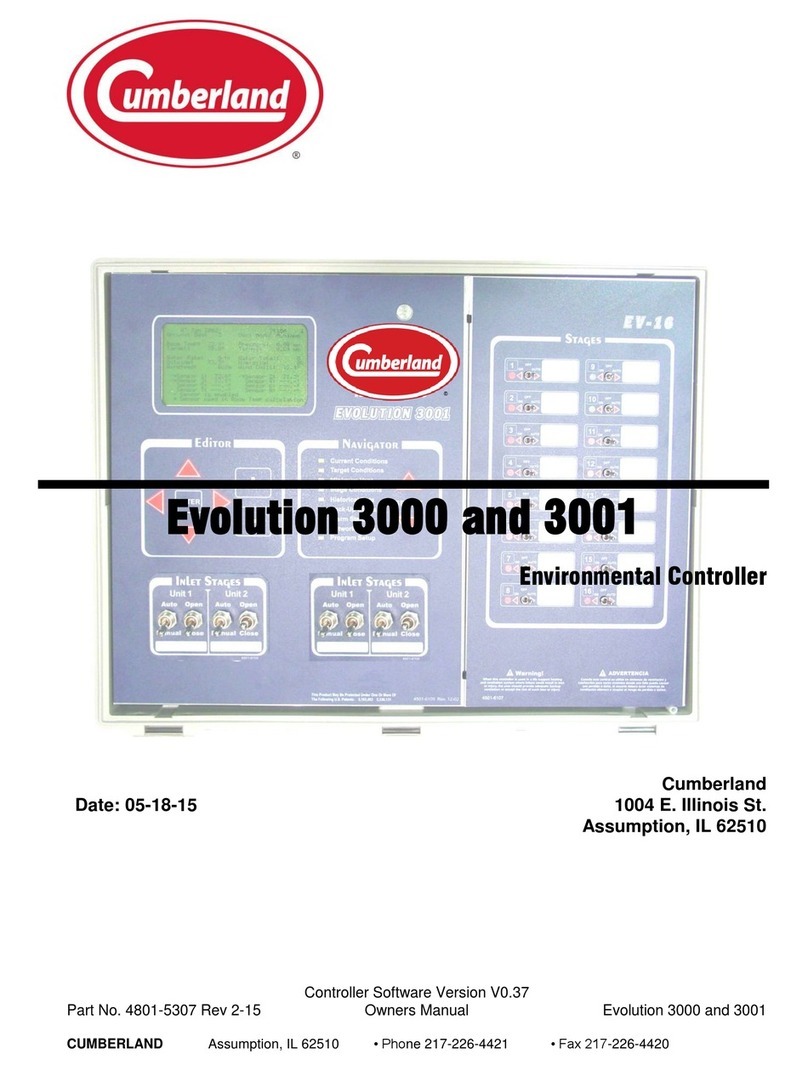
Evolution 4000
Environmental Controller
Cumberland
Date: 05-18-15 1004 E. Illinois St.
Assumption, IL 62510

Part No. 4801-5338 Rev 2-2015 Evolution 4000 2 of 86
Table of Contents
Section Title Page
1. Warranty.......................................................................................................Error! Bookmark not defined.
2. Warnings........................................................................................................................................................5
3. Ratings and Specifications.............................................................................................................................6
4. Introduction ...................................................................................................................................................7
5. Evolution Front Panel....................................................................................................................................8
5.1 Navigator Panel ......................................................................................................................................9
5.1.1 Select System View.........................................................................................................................9
5.2 Editor Panel ..........................................................................................................................................10
5.2.1 Main Display Contrast ..................................................................................................................10
5.2.2 Page UP/DOWN...........................................................................................................................11
5.2.3 Language.......................................................................................................................................11
5.3 Stage Switch .........................................................................................................................................12
5.3.1 Inlet Stages....................................................................................................................................12
5.4 Status Display.......................................................................................................................................13
5.5 Locks ....................................................................................................................................................13
6. Viewing Navigator Status Screens...............................................................................................................13
6.1 Current Conditions –MAIN SYSTEM.................................................................................................14
6.2 Target Conditions –MAIN SYSTEM..................................................................................................15
6.2.1 Target Conditions - Standard Screen With Optimum Mode OFF.................................................15
6.2.2 Target Conditions –Optimum Screen With Optimum Mode ON.................................................16
6.3 Timers & Clocks –MAIN SYSTEM....................................................................................................17
6.4 Stage Conditions –MAIN SYSTEM....................................................................................................18
6.4.1 Inlet Conditions.............................................................................................................................20
6.4.2 On/Off Stages................................................................................................................................21
6.4.3 Natural Ventilation Stages ............................................................................................................22
6.4.4 Variable Stages.............................................................................................................................22
6.5 Historical Data –MAIN SYSTEM.......................................................................................................23
6.5.1 Alarm Log.....................................................................................................................................23
6.5.2 Room Temperature .......................................................................................................................23
6.5.3 Stage Run Times...........................................................................................................................24
6.5.4 Humidity #1 (Room) & Humidity #2 (Cooler) .............................................................................24
6.5.5 Water Usage (#1 or #2).................................................................................................................24
6.5.6 Ventilation Mode..........................................................................................................................24
6.5.7 Feed History..................................................................................................................................25
6.6 Alarm Status –MAIN SYSTEM ..........................................................................................................25
6.6.1 High Temperature Alarm Details..................................................................................................26
6.6.2 Low Temperature Alarm Details...................................................................................................27
6.6.3 Tunnel Vent Alarm Details...........................................................................................................27
6.7 Program Set-Up ....................................................................................................................................28
6.8 Current Conditions –AUXILIARY SYSTEM .....................................................................................29
6.9 Historical Data –AUXILIARY SYSTEM ...........................................................................................29
6.10 Alarm Status –AUXILIARY SYSTEM...............................................................................................30
6.11 Current Conditions –BACK-UP SYSTEM..........................................................................................30
7. Setting Programming Functions...................................................................................................................31
7.1 General Settings....................................................................................................................................31
7.2 Network Status......................................................................................................................................32
7.3 Temperature Sensors.............................................................................................................................32
7.4 Feed Level Sensors...............................................................................................................................32
7.5 Ventilation Inlets...................................................................................................................................33
7.6 Natural Ventilation ...............................................................................................................................34
7.7 Growout Curve .....................................................................................................................................35
7.7.1 Growout Curve With Optimum Mode OFF..................................................................................35
7.7.2 Growout Curve With Optimum Mode ON....................................................................................36
7.8 Tunnel Ventilation................................................................................................................................39
7.9 ON/OFF Stages.....................................................................................................................................39

Part No. 4801-5338 Rev 2-2015 Evolution 4000 3 of 86
7.9.1 On/Off Stage Details.....................................................................................................................40
7.10 Variable Stage Outputs .........................................................................................................................41
7.11 Stage Properties....................................................................................................................................42
7.11.1 Heat Properties..............................................................................................................................42
7.11.2 Cool Stir Properties.......................................................................................................................42
7.11.3 Cool Negative Properties..............................................................................................................42
7.11.4 Cool Negative Tunnel Properties..................................................................................................43
7.11.5 Cool Tunnel Properties.................................................................................................................43
7.11.6 Cool Evaporative Properties.........................................................................................................44
7.11.7 Natural Ventilation Properties ......................................................................................................44
7.12 Setup Feed Clocks ................................................................................................................................45
7.12.1 Feed Clock Schedules...................................................................................................................45
7.13 Setup Light Clocks................................................................................................................................46
7.13.1 Light Clock Details.......................................................................................................................46
7.14 Seasonal Programs & Security..............................................................................................................46
7.15 Diagnostics ...........................................................................................................................................47
7.16 SD Card Operations..............................................................................................................................49
7.16.1 Save/Load Programs.....................................................................................................................49
7.16.2 Save Programs ..............................................................................................................................50
7.16.3 Load Programs..............................................................................................................................51
7.16.4 Update Controller Software Version.............................................................................................52
8. ALWAYS Back-Up Setting.........................................................................................................................54
9. Wiring Diagrams..........................................................................................................................................55
9.1 Inside the Evolution 4000 Enclosure ....................................................................................................55
9.2 Voltage Selection Internal Wiring for the EV4000 Controller .............................................................56
9.3 Setting Address Switches & LEDs on PCB 191 Stage Board...............................................................57
9.4 Connecting Temperature Sensor to Evolution 4000 .............................................................................58
9.5 Connecting Static Pressure Sensor to Evolution 4000..........................................................................59
9.6 Connecting Humidity Sensor to Evolution 4000...................................................................................60
9.7 Connecting HHnet PC Network to Evolution 4000 ..............................................................................61
9.8 Connecting Alarm Device to Evolution 4000.......................................................................................61
9.9 Connecting Water Meter to Evolution 4000 .........................................................................................62
9.10 Connecting Stage Jumpers of Evolution 4000 ......................................................................................63
9.11 Applying Inlet Stage Labels to the Evolution 4000 Cover Label..........................................................64
9.12 Connecting the PowerTrak to the Evolution 4000................................................................................65
9.13 Connecting the PowerTrak and S-3 Back-Up to the Evolution 4000....................................................66
9.14 Connecting the PowerTrak Power Auxiliary Switches to Evolution 4000............................................67
9.15 Connecting PowerTrak Natural Auxiliary Switches NV#1 & NV#2 to Evolution 4000 ......................68
9.16 Connecting PowerTrak Natural Auxiliary Switches NV#3 & NV#4 to Evolution 4000 ......................69
9.17 Evolution 4000 Power Connection .......................................................................................................70
9.18 Connecting Local Network & Backup to the Evolution 4000...............................................................71
10. Temperature vs. Sensor Resistance Table....................................................................................................72
11. Label Quick-Reference Information ............................................................................................................73
12. Parts List......................................................................................................................................................74
Poultry House Layout and Specification..............................................................................................................80
1. House Specification.....................................................................................................................................80
2. Stage Programming......................................................................................................................................81
3. Temperature Curve......................................................................................................................................82
4. Static Pressure Settings................................................................................................................................82
5. Minimum Vent.............................................................................................................................................82
6. Tunnel Settings............................................................................................................................................82
7. Lighting Program.........................................................................................................................................83
8. Feed Program...............................................................................................................................................83
9. Back-up Specifications ................................................................................................................................84
10. Alarm Specifications....................................................................................................................................84
11. Notes............................................................................................................................................................85
Part No. 4801-5338 Rev 2-2015 Evolution 4000 4 of 86
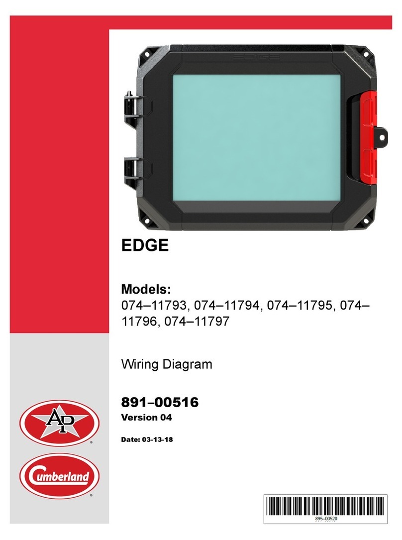
Limited Warranty
1. Warranty
The GSI Group, LLC. (“GSI”) warrants products which it manufactures to be free of defects in materials and
workmanship under normal usage and conditions for a period of 12 months after sale to the original end-user or if a
foreign sale, 14 months from arrival at port of discharge, whichever is earlier. The end-user’s sole remedy (and
GSI’s only obligation) is to repair or replace, at GSI’s option and expense, products that in GSI’s judgment, contain
a material defect in materials or workmanship. Expenses incurred by or on behalf of the end-user without prior
written authorization from the GSI Warranty Group shall be the sole responsibility of the end-user.
Warranty Extensions:The Limited Warranty period is extended for the following products:
Product
Warranty
Period
AP Fans and
Flooring
Performer Series Direct Drive
Fan Motor
3 Years
All Fiberglass Housings
Lifetime
All Fiberglass Propellers
Lifetime
AP/Cumberland
Flex-Flo/Pan Feeding Systems
2 Years
Cumberland
Feeding/Watering
Systems
Feeder System Pan Assemblies
5 Years **
Feed Tubes (1.75" & 2.00")
10 Years *
Centerless Augers
10 Years *
Watering Nipples
10 Years *
Grain Systems
Grain Bin Structural Design
5 Years
Grain Systems
Farm Fans
Zimmerman
Portable & Tower Dryers
2 Years
Portable & Tower Dryer Frames
and Internal Infrastructure †
5 Years
GSI further warrants that the frame, basket and excluding all auger and auger drive components of the portable
and tower dyer shall be free from defects in materials for a period of time beginning on the twelth (12th) month
from the date of purchase and continuing until the sixtieth (60th) month from the date of purchase (extended
warranty period). During the extended warranty period, GSI will replace the frame or basket components that
prove to be defective under normal conditions of use without charge, excluding the labor, transportation, and/or
shipping costs incurred in the performance of this extended warranty.
Conditions and Limitations:
THERE ARE NO WARRANTIES THAT EXTEND BEYOND THE LIMITED WARRANTY DESCRIPTION SET
FORTH ABOVE. SPECIFICALLY, GSI MAKES NO FURTHER WARRANTY OF ANY KIND, EXPRESS OR
IMPLIED, INCLUDING, WITHOUT LIMITATION, WARRANTIES OF MERCHANTABILITY OR FITNESS FOR A
PARTICULAR PURPOSE OR USE IN CONNECTION WITH: (i) PRODUCT MANUFACTURED OR SOLD BY
GSI OR (ii) ANY ADVICE, INSTRUCTION, RECOMMENDATION OR SUGGESTION PROVIDED BY AN AGENT,
REPRESENTATIVE OR EMPLOYEE OF GSI REGARDING OR RELATED TO THE CONFIGURATION,
INSTALLATION, LAYOUT, SUITABILITY FOR A PARTICULAR PURPOSE, OR DESIGN OF SUCH PRODUCTS.
GSI shall not be liable for any direct, indirect, incidental or consequential damages, including, without limitation,
loss of anticipated profits or benefits. The sole and exclusive remedy is set forth in the Limited Warranty, which
shall not exceed the amount paid for the product purchased. This warranty is not transferable and applies only to
the original end-user. GSI shall have no obligation or responsibility for any representations or warranties made
by or on behalf of any dealer, agent or distributor.
GSI assumes no responsibility for claims resulting from construction defects or unauthorized modifications to
products which it manufactured. Modifications to products not specifically delineated in the manual
accompanying the equipment at initial sale will void the Limited Warranty.
This Limited Warranty shall not extend to products or parts which have been damaged by negligent use, misuse,
alteration, accident or which have been improperly/inadequately maintained. This Limited Warranty extends
solely to products manufactured by GSI.
Prior to installation, the end-user has the responsibility to comply with federal, state and local codes which apply
to the location and installation of products manufactured or sold by GSI.
* Warranty prorated from list price:
0 to 3 years –no cost to end-user
3 to 5 years –end-user pays 25%
5 to 7 years –end-user pays 50%
7 to 10 years –end user pays 75%
** Warranty prorated from list price:
0 to 3 years –no cost to end-user
3 to 5 years –end-user pays 50%
†Motors, burner components and
moving parts not included. Portable
Dryer screens included. Tower Dryer
screens not included.

Part No. 4801-5338 Rev 2-2015 Evolution 4000 5 of 86
2. Warnings
Warning!
Maximum operating temperature of controller is 50C (122F).
Use adequate ventilation to reduce the risk of overheating of controller!
Warning!
When this controller is used in a life support heating and ventilation system
where failure could result in loss or injury, the user should provide adequate
back-up, or accept the risk of such loss or injury!

Part No. 4801-5338 Rev 2-2015 Evolution 4000 6 of 86
EVOLUTION 4000 DIMENSIONS
16.25”
32.25”
23.75”
9.75”
3. Ratings and Specifications
HHI Part
Number
Model
Power Supply
Stage Output
ROOM TEMP
6607-8220
EV-4000 40 Stage Controller
120/230 VAC 50/60 Hz
1-1/2 HP @ 240 VAC
Minimum 32°F/0°C;
Maximum 122°F/50°C
6607-8221
EV-4000 24 Stage Controller
120/230 VAC 50/60 Hz
1-1/2 HP @ 240 VAC
Minimum 32°F/0°C;
Maximum 122°F/50°C
NOTE: Room Temperature Must Be Kept Between 32F/0C and 122F/50C.

Part No. 4801-5338 Rev 2-2015 Evolution 4000 7 of 86
4. Introduction
The Evolution 4000 Controller is the newest member of Cumberland‟s environmental controller line. The
Evolution 4000 Controller has the same operational features as the 3001 except the 4000 has the following
NEW features/capabilities:
Stage capability is now increased to 40 stages; Consolidated inside one control box. The Evolution
4000 Controller can be expanded up to 56 stages using a EV-16 Expansion Module (p/n: 6607-
8016).
NEW user-friendly and versatile wire connection interface included with the I/O Board and Stage
Relay Boards.
Software upgrades to the main PCB197 control board are downloaded from a standard SD Card.
Updated and improved software functionality.
Status and Power indication LEDs‟allow trouble-shooting at-a-glance.
New & Improved Control Panel User Interface allows display contrast adjustment, scroll through
displayed information a page-at-a-time, or toggle between English and Spanish languages quickly
and easily.
Quickly navigate to the Main, Auxiliary, or Backup System Views at the push of a button.
Features:
Input Device Options
8 inside temperature sensors
1 outside temperature sensor
2 humidity sensors
1 static pressure transducer
2 digital water meter input
HHNet connection for PC compatibility
PowerTrak auxiliary switch inputs
2 Feed Bin Level Sensors
2 Auger Runtime Sensors
Output Devices (Standard)
40 On/Off output stages with manual override switches
(2) 0-10 Vdc Analog Outputs
1 Alarm relay with both N.O. and N.C. contacts
Output Devices: (Optional)
Variable speed output drive
16 On/Off output stages with manual override switches
Patented integrated Evolution Back-up & Evolution S3

Part No. 4801-5338 Rev 2-2015 Evolution 4000 8 of 86
EVOLUTION 4000 FRONT PANEL
Navigator
Buttons
Stage switches
(ON, OFF,
AUTO)
'Stage On'
Indicators
White spaces
are for stickers
to identify stage
operations
Editor Buttons
Main Display
Contrast
Adjustment
System
View
Page Display
Up & Down
Toggle
Language
Tue 15 Sep 2009 10:45a
Growout Day: 258
Ventilation Mode: Minimum
Room Temp:
71.4°
Target:
70.0°
Pressure:
0.00 wc
Target:
0.04 wc
Humidity:
0%
Target <
60%
Outside:
77.0°
Enclosure:
95.0°
Water Consumption
Feed Levels
1. 240
(10/hr)
1. 11.2ft
( 60%)
2. 280
(10/hr)
2. 5.0ft
( 23%)
PAGE for Details
5. Evolution Front Panel
The Evolution 4000 Controller cover is divided into two main areas. The main control user interface is
located on the top-half of the panel and contains the Main Display, Editor and Navigator user interface
controls. The Stage Switches are located on the bottom-half of the front panel. The Navigator is used to
select the information to be displayed in the Main Display. Once the desired information is selected in the
Navigator, the Editor is used to scan and modify the data, adjust the display contrast, page-scroll through the
displayed information screens, or toggle the displayed information between English and Spanish languages.

Part No. 4801-5338 Rev 2-2015 Evolution 4000 9 of 86
5.1 Navigator Panel
The Navigator buttons are used to select a controller function. Press up or down button to toggle between
functions. LED (light emitting diode) lights when a function is selected and the associated data is displayed
in the Main Display.
5.1.1 Select System View
The Select System View SELECT button is used to toggle between the Main, Auxiliary, or Back-Up
controller system views. LED (light emitting diode) lights when a function is selected and the associated
data is displayed in the Main Display. Scroll through seven of the MAIN System View Navigator sections
by using the Select UP and DOWN arrows. The Auxiliary System is used to monitor a separate room which
is typically an egg/cooler room in certain applications. The Auxiliary System View has three Navigator
sections (Current Conditions, Historical Data, & Alarm Status). The Back-Up System View has the one
Current Conditions Navigator section which is a quick link to show the back-up system status information
concerning back-up operation (Targets, limits, alarm status and other information detailed in Section 6.11).
Function Modes
Up Select Button
Down Select
Button
Light Emitting
Diode Indicator
System Modes
System Select
Button
System Modes
System Select
Button
Up Select Button
Down Select
Button
Light Emitting
Diode Indicator
Light Emitting
Diode Indicator

Part No. 4801-5338 Rev 2-2015 Evolution 4000 10 of 86
5.2 Editor Panel
The Editor buttons are used to select functions that appear in the Main Display screen. The arrow buttons
are used to scroll to variables that appear within the current screen of the Main Display. The plus (+) and
minus (-) buttons are used to change or modify a variable's value. The Enter button is used to link to a new
display screen of a selected variable. NOTE: To return to the main function screen, press either Up () or
Down () Navigator button.
5.2.1 Main Display Contrast
The main display contrast can be adjusted to adapt to various lighting conditions. The Contrast Control is
located in the front panel Editor section. Use the Contrast Control to darken or lighten the screen text. The
contrast button will change the contrast in both directions. If you press & hold the contrast button, it will
move in one direction. If you would like to reverse directions, release button for at least one second and
then press again. It will now adjust in the opposite direction.
Minus button
(Use to decrease
value of variable)
Enter Button
(Links to other
screens)
Plus button
(Use to increase
value of variable)
Scroll Buttons
Contrast Button
(Increase or Decrease
Screen Contrast)
Page Up/Down Button
Language button
(Use to toggle between
English and Spanish )
Contrast Button
(Increase or Decrease
Screen Contrast)

Part No. 4801-5338 Rev 2-2015 Evolution 4000 11 of 86
5.2.2 Page UP/DOWN
The Page UP/DOWN button can be used to quickly scroll through pages/screens of information at a time
instead of scrolling one line at a time. The Page UP/DOWN button is located in the front panel Editor
section. After displaying the last line of information, pressing the Page UP/DOWN button once more will
jump back to the top line of information.
5.2.3 Language
The LANGUAGE button can be used to quickly toggle all display content from English to Spanish or from
Spanish to English with only the press of one button. This feature is a time-saver, especially when various
language personnel either monitors and/or changes settings on a daily basis. No system setup menu‟s to sort
through each time that Spanish or English language is preferred. The LANGUAGE button is located in the
front panel Editor section.
Page Up/Down Button
Language Button

Part No. 4801-5338 Rev 2-2015 Evolution 4000 12 of 86
5.3 Stage Switch
The stage LED indicator lights when a stage is active. The stage switch is used to select Auto operation,
On, or Off. If switch is in Auto position, the stage operation is controlled by the controller. That is, the
stage may turn on and off according to settings selected from the Main Display screen. If switch is in the
On position, a stage is On continuously. If switch is in the Off position, a stage is Off with the exception of
Back-Up conditions.
The white space is used to affix a label indicating stage function (i.e. brooder, fan, light, cool, etc.)
NOTE: Stages 1-40 are marked on the controller front panel. For optional Inlet Stages, use stick-on label
to apply to two side-by-side stages.
5.3.1 Inlet Stages
Optional inlet stages may be added to control vents & curtains. When Auto/Manual toggle switch is placed
in Auto position, inlet opens and closes according to programmed instructions. Use the Open/Close toggle
switch to manually open or close inlet when Auto/Manual toggle switch is placed in Manual position. The
Notation area is for labeling the inlet. Refer to Section 9.11 for additional Inlet Stages details.
Under normal circumstances the machines should be left in automatic (Auto) as shown above.
IMPORTANT!
Stages that are programmed to be open/close stages must follow two rules. First, they
must be consecutive, and second, they must start on an odd stage. The open output
will always be the odd stage and the close stage will always be the even stage.
Manually opens or
closes inlet
Controller opens or
closes inlet
Notation Area
Toggle Switch
(Auto or Manual
Operation)
Toggle Switch
(Open or Close
Operation)
Opens Inlet
(Manual Oparation)
Closes Inlet
(Manual Oparation)
Stage number
(Use labels to denote
stages 17-64)
Stick Icon label onto white
area or use for notation.
LED Indicator (lights
when stage is ON)
Icon labels are provided to
affix to white area of stage
control. Icon symbols are
shown at right.
Heater Negative Fan
Light StirFan
Neg./Tun. Feed Evap. Cooling Tunnel Fan
ON, OFF, AUTO
Switch positions

Part No. 4801-5338 Rev 2-2015 Evolution 4000 13 of 86
** PASSWORD PROTECTED **
You must enter the current controller
Password to continue.
Press the ENTER button to proceed.
Password: XXXX
5.4 Status Display
The following is an example of Main Display screen displaying a portion of the standard Alarm status
screen. The Main Display screen displays both status and programming screens.
5.5 Locks
A lock feature has been included for additional
security to the Evolution 4000 settings. This
feature locks the Program Setup screens to
prevent changes. Locked screens are noted by
a lock symbol ( ) in the upper right of the
screen. The Target Conditions and Minimum
Vent screens are not lockable. When the lock
feature is disabled ( ), all screens will show
unlocked until the password is changed. See
Section 7.14.
NOTE: The Diagnostics screen can only be unlocked using the HHI Service Code; Contact your local
dealer for assistance.
6. Viewing Navigator Status Screens
The following seven screens are available: Current Conditions, Target Conditions, Timers & Clocks, Stage
Conditions, Historical Data, Alarm Status, Program Setup. The Navigator selects the desired status screen
by pressing the up and down SELECT arrows. The first screens display status information and various
setup options. The last screen is the Program Screen. To change program parameters the Program Setup
Screen must be selected.
TEMPERATURE LIMIT STATUS LAST ALARM
(1)High Temp85.0° OK 08/15-10:36p
(2)Low Temp65.0° OK 08/10-03:36p
PRESSURE LIMIT STATUS LAST ALARM
(3)Cycle Press 0.04 Off 08/09-07:36p
(4)High Press 0.15 Off 07/22-01:36p
(5)Low Press 0.03 Off 07/13-06:36p
85.0°
The Scroll Symbol is a
flashing down arrow () that
indicates more text outside
of display screen. Use
up/down editor arrow keys
to scroll text or use the
Page Button.
The Link Symbol () is a right
pointing arrow and indicates a
link to another display screen.
To change
parameter:
Select parameter
using editor
arrow keys. Use
+ and - keys to
change value.

Part No. 4801-5338 Rev 2-2015 Evolution 4000 14 of 86
Tue 15 Sep 2009 10:45a
(1) Growout Day: 258
(2) Ventilation Mode: Minimum
(3) Room Temp:
71.4°
Target:
70.0°
(4) Pressure:
0.00 wc
Target:
0.04 wc
(5) Humidity:
0%
Target <
60%
(6) Outside:
77.0°
(7) Enclosure:
95.0°
(8)Water Consumption
(9) Feed Levels
1. 240
(10/hr)
1. 11.2ft
( 60%)
2. 280
(10/hr)
2. 5.0ft
( 23%)
PAGE for Details
(10)Sensor enabled
* Sensor in Room Temp
* Sensor 1: 71.6°
* Sensor 2: 71.2°
* Sensor 3: 71.4°
Sensor 4:---.-°
Sensor 5:---.-°
Sensor 6:---.-°
Sensor 7:---.-°
Sensor 8:---.-°
NOTE: In this manual, Reference
numbers refer to descriptions given in
text. These numbers do not appear
on display.
6.1 Current Conditions –MAIN SYSTEM
The current environmental conditions of the building are shown here. Below is a table describing the
variables that can appear in the Current Conditions status screen.
The numbers in brackets e.g. (1) refer to the descriptions below the sample screen displays.
(1) Growout Day –The current day in the growout period. The Current Conditions LED on the Navigator
panel will blink if the growout day is later then the current date.
(2) Vent Mode –Indicates the current ventilation mode: either Minimum, Natural, Power, Transition or
Tunnel.
(3) Room Temp –The average temperature of the sensors for display. Target-–Target Temperature.
(4) Pressure –The current atmospheric pressure internal to the building. Target-–Target Pressure.
(5) Humidity –The percent of water vapor of the air inside the building.
(6) Outside (Temperature) –The outside temperature as indicated by the outside sensor.
(7) Enclosure (Temperature) –The temperature inside the controller.
VENT MODE
Definition
Minimum
Heat stages or timer fans operating. None of the negative stages are on because of
temperature.
Natural
The main curtains are open.
Power
The curtains are up and there are negative fans on because of temperature.
Transition
The control is transitioning into tunnel ventilation from either power or natural
ventilation. The control is making the adjustments needed to go into tunnel.
Tunnel
The tunnel signal has been activated and the system has entered into tunnel.
(8) Water Consumption –Water consumed for the current day; The total for the day is listed first then the
units per hour is shown inside ( ). Two water meters may be monitored (Water
Meter 1 & Meter 2).
(9) Feed Level –The Feed level is shown in number of feet from the bottom first then the percentage of
feed remaining in the feed bin is shown inside ( ). Two feed bins may be monitored (Bin
#1 & Bin #2).
(10) Sensor 1 through 8 –The current temperature read by each sensor.

Part No. 4801-5338 Rev 2-2015 Evolution 4000 15 of 86
(1)Target Temp =
77.5°
(2)Ramping:
On
(3)Target Press =
0.04 wc
(4)Ramping:
Off
(5)Tunnel Press =
0.00 wc
(6)Target Humidity
< 60%
6.2 Target Conditions –MAIN SYSTEM
The current target environmental conditions of the building are shown below. The specific Target
Conditions screen features and setting options will depend on whether Optimum Mode is ON or OFF.
Examples and details for both the Standard screen and Optimum screen are shown in the following two
subsections.
6.2.1 Target Conditions - Standard Screen With Optimum Mode OFF
(1) Target Temp - This is the desired temperature of
the building.
(2) Ramping –Indicates if ramping of the Target
Temperature is turned On or Off. You are also
allowed to turn the temperature ramping on or off
in the program set up screen. You use the
Navigator to reach the Program Setup screen and
then navigate down to "Temperature Ramp" and
press enter. See Section 7.7.
(3) Target Press - This is the desired negative
pressure in the building. See Section 7.5.
(4) Ramping –Indicates if ramping for the Target
Pressure is turned on: On or Off. You are also
allowed to turn the pressure ramping on or off in
the program setup screen. See Section 7.5.
(5) Tunnel Pressure –Indicates the desired negative
pressure in the building while in the Tunnel
Mode. See Section 7.5.
(6) Target Humidity –The desired humidity inside
the building (Humidity Sensor # 1) is less than
this set number. For every percentage increase in
humidity over the set %, the timer percentage
will increase.
EXAMPLE:
Target Humidity < 65%
Timer Percentage is set to 20% of 5 minutes.
If Humidity in building is at 70%, the timer
percentage will be at 25%.
NOTE: This only affects the variable timer %.
Min1% and Min2% are unaffected.

Part No. 4801-5338 Rev 2-2015 Evolution 4000 16 of 86
Optimum Settings
Adjustments
(1)Target Temp:
77.5°
(2)Adjust =
+0.0°
(3)Optimum Run%:
10%
(4)Adjust =
+00%
(5)Target Press:
0.04 wc
(6)Tunnel =
0.00 wc
(7)Humidity <
60%
(8)Growout Curve Settings
(9)Current Optimum Base %:
10%
(10)Optimum Timer Active:
--6-4---
(11)Maximum Tunnel Fans Allowed:
4
(12)Tunnel Stage Adjustment:
+ 0.0°
(13)Heat Stage Adjustment:
- 0.0°
6.2.2 Target Conditions –Optimum Screen With Optimum Mode ON
The target conditions screen shown below represents the display and options when the Optimum Mode is
turned On. Refer to Section 7.1 for turning the Optimum Mode On or Off and Section 7.7.2 for the
Optimum Mode Growout Curve.
(1) Target Temp –Displays the desired temperature of the building for the current growout day.
(2) Adjust –Adjusts the programmed Target Temperature by this amount until set otherwise. The displayed Target
Temp to the left will increase or decrease as this number is adjusted.
(3) Optimum Run% –Displays the minimum vent run % for the current growout day. The Run % is the
percentage of the Minimum Timer Cycle that the stage will run.
(4) Adjust –Adjusts the programmed Optimum Run% by this amount until set otherwise. The displayed Optimum
Run% to the left will increase or decrease as this number is adjusted.
(5) Target Press - This is the desired negative pressure in the building. See Section 7.5.
(6) Tunnel Pressure –Indicates the desired negative pressure in the building while in the Tunnel Mode. See
Section 7.5.
(7) Humidity –The desired target humidity inside the building (Humidity Sensor # 1) is less than this set number.
For every percentage increase in humidity over the set %, the timer percentage will increase.
EXAMPLE:
Target Humidity < 65%
Timer Percentage is set to 20% of 5 minutes.
If Humidity in building is at 70%, the timer percentage will be at 25%.
NOTE: This only affects the variable timer % and Optimum Run %. Min1% and Min2% are unaffected.
(8) Growout Curve Setting –Links to the Optimum Growout Curve Setting screen. Refer to Section 7.7.2.
(9) Current Optimum Base % –The current optimum base run percentage based on the growout curve.
(10)Optimum Timer Active –Displays the current optimum timer active determined by the growout curve.
(11)Maximum Tunnel Fans Allowed –Displays the current maximum number of tunnel fans allowed as
determined by the growout curve.
(12)Tunnel Stage Adjustments –Displays the current calculated tunnel stage adjustments as determined by the
growout curve.
(13)Heat Stage Adjustments –Displays the current calculated heat stage adjustments as determined by the growout
curve.

Part No. 4801-5338 Rev 2-2015 Evolution 4000 17 of 86
(1)Light Schedule
(2)Feed Schedule
(3)MINIMUM TIMERS:
(4)Cycle= 5 m ( 300s)
(8)VARIABLE SPEED:
(5)Min1%= 40% ( 215s)
(9)V1 Min%= 50%( 55%)
(6)Min2%= 20% ( 108s)
(10)V2 Min%= 40%(100%)
(7)Var%: 20% ( 108s)
(11)VARIABLE TIMER:
(12)Sensors = Outside-
(13)Max Run % = 65%
(14)Max Temp = 85.0°
(15)Min Run % = 20%
(16)Min Temp = 70.0°
(17)COOL TIMER:
(18)Max Run % = 100%
(19)Cycle = 10 m ( 600s)
(20)Min Run % = 55%
NOTE: Cycle in seconds
NOTE: Run Time in seconds
6.3 Timers & Clocks –MAIN SYSTEM
The Minimum Vent status screen display:
(1) Light Schedule –Displays the current Light Clock
Schedule. See Section 7.13.
(2) Feed Schedule –Displays the current Feed Clock
Schedule. See Section 7.12.
(3) Minimum Timer 1 - The Minimum timer one and
two both share the same cycle time. Different timer
percentages may be set for minimum 1 vs. minimum
2. If the vent anticipation is being used, the vents
will start opening before a negative ventilation stage
turns on and will adjust until the vent opening
necessary for the desired target pressure is achieved.
(4) Cycle - The length of Timer 1 cycle. Cycle = 1 to
20 minutes.
(5) Min1 % - The percentage of the Timer 1 cycle that
the stage will run.
(6) Min2 % - The percentage of the Timer 2 cycle that
the stage will run.
(7) Var % - The percentage of time a stage is currently
running using the variable timer based off the
temperature.
NOTE: The Minimum timer one and two both share
the same cycle time. Different timer percentages
may be set for Minimum 1 and Minimum 2. If the
vent anticipation is being used, both Minimum 1 and
Variable will start the vents open before a stage
comes on.
(8) Variable Speed: These settings are used to set up
variable speed fan operation.
(9) V1 Minimum - The minimum speed or minimum
percentage of light intensity for V1; The value
inside the parenthesis shows the current percentage.
(10) V2 Minimum -The minimum speed or minimum
percentage of light intensity for V2; The value
inside the parenthesis shows the current percentage.
(11) Variable Timer - The variable timer will vary the
timer based on temperature. See chart shown
below.
(12) Sensors - The sensors used to determine the run
time. Active sensors will be indicated by a number
starting with #1 from right to left. Inactive sensors
will be indicated by a - or hyphen. When "outside-"
is displayed, outside sensor is active. For example, If
sensors 1, 2 and 3 are being used, "-----321" will be
displayed. When “outside” is displayed, the outside
sensor is active.
(13) Max Run % - The maximum Run Time
percentage.
(14) Max Temp - The temperature at which the timer
will run Maximum Run time % percentage.
(15) Min Run % - The minimum Run Time
percentage.
(16) Min Temp - The minimum temperature. The
timer will be at minimum Run %.

Part No. 4801-5338 Rev 2-2015 Evolution 4000 18 of 86
(17) Cool Timer: Cool timer is also allowed a different
timer cycle if needed. This can be used for foggers
or cool cell systems.
(18) Max Run - The Cool Timer Maximum Run Time
percentage.
(19) Cycle - Cycle Time in Minutes. Cool timer is also
allowed a different timer cycle if needed. This will
be used for foggers or cool cell systems.
(20) Min Run - The Cool Timer Minimum Run Time
percentage.
6.4 Stage Conditions –MAIN SYSTEM
When the Stage Conditions screen is selected by using the Navigator Select arrows, the following menu
screen is shown. Use the up and down arrows in the Editor to view the desired information. The listing
order from top to bottom is Inlet Stages, Feed, Light, or Aux Ventilation Stages. Notice that the Light
Clock and Feed Clock Stages are listed after the Inlet Conditions section. The Heat Stages are then
displayed in order of increasing ON Temperatures. The Cool stages, including the Variable Output stages,
are listed below the Target Line in order of increasing ON Temperatures.

Part No. 4801-5338 Rev 2-2015 Evolution 4000 19 of 86
Refer to Section 6.4.2 & 7.9.
When Mode=Off, those stages will not
be visible on the Stage Conditions
Screen.
STAGE CONDITIONS SCREEN EXAMPLE:
Refer to Section 7.13.
Refer to Section 6.4.3, 7.6, & 7.11.7.
Target: The desired temp. of the building.
Enter Tun: Fans enter Tunnel at set temp.
Exit Tun: Fans exit Tunnel at set temp.
N/A: The stage is not allowed to turn on with the current set conditions.
Off: The stage is currently OFF.
On: The stage is currently ON.
Timed: The stage is currently ON with a timer.
Refer to Section 7.12.
Refer to Section 6.4.1 & 7.5.
Refer to Section 6.4.3 & 7.6.
Refer to Section 7.9 and 7.11.1.
Refer to Section 7.11.2.
Refer to Section 7.11.3.
Refer to Section 7.11.4.
(1)Stage Properties
#
STATUS
MODE
RTEMP
ON
OFF
TIME
1
On
Attic Open
<ACTIVE>
2
Off
Attic Close
<ACTIVE>
3
Off
Vent Open
<CLOSED>
4
On
Vent Close
<CLOSED>
5
Off
Tunnel 1 Open
<CLOSED>
6
On
Tunnel 1 Close
<CLOSED>
7
Off
Tunnel 2 Open
<CLOSED>
8
On
Tunnel 2 Close
<CLOSED>
9
Off
Natural 1 Open
<ACTIVE>
10
On
Natural 1 Close
<ACTIVE>
11
On
Light
Ramp
12
On
Light
Ramp
13
Off
Feed
Sch1
14
Off
Feed
Sch2
15
Off
Heat
86.0°
77.5°
79.0°
None
16
Off
Heat
86.0°
77.5°
79.0°
None
17
Off
Heat
86.0°
77.5°
79.0°
None
18
Off
Heat
86.0°
75.0°
77.0°
None
-----------
TARGET
80°
---------
19
Off
Cstir
86.0°
82.0°
81.0°
Min1
20
Off
Cstir
86.0°
82.0°
81.0°
21
Off
Cstir
86.0°
82.0°
81.0°
22
Off
CNeg
86.0°
82.5°
81.0°
23
Off
CNeg
86.0°
82.5°
81.0°
24
Off
CNeg
86.0°
83.0°
81.5°
25
On
CNegT
86.0°
83.0°
82.0°
26
On
CNegT
86.0°
84.0°
83.0°
27
On
CTUN
86.0°
84.5°
83.0°
28
On
CTUN
86.0°
85.0°
84.0°
29
On
CTUN
86.0°
86.0°
85.0°
30
Off
CTUN
86.0°
88.0°
86.0°
31
Off
CTUN
86.0°
90.0°
88.0°
-----------
MAXIMUM TUNNEL FANS
----------
32
Off
CEVAP
86.0°
92.0°
87.0°
Var
33
Off
CEVAP
86.0°
92.0°
87.0°
Var
34
Off
Off
35
Off
Off
36
Off
Off
37
Off
Off
38
Off
Off
39
Off
Off
40
Off
Off
U1
On
NAT CLOSE
---.-
90.0°
CLOSED:No
U2
On
NAT CLOSE
---.-
90.0°
CLOSED:No
U3
On
NAT CLOSE
---.-
90.0°
CLOSED:No
U4
On
NAT CLOSE
---.-
90.0°
CLOSED:No
U1
Off
NAT OPEN
---.-
92.0°
CLOSED:No
U2
Off
NAT OPEN
---.-
92.0
CLOSED:No
U3
Off
NAT OPEN
---.-
92.0
CLOSED:No
U4
Off
NAT OPEN
---.-
92.0
CLOSED:No
---
On
Exit Tun
---.-
----
83.0
----
---
On
Enter Tun
---.-
86.0
----
----
Refer to Section 6.4.1, 7.5 & 7.8.
Refer to Section 7.11.6.
Maximum Tunnel Fans: The maximum number
of tunnel fans will be turning ON from this point
downward with hotter temperatures.
Refer to Section 7.11.5.

Part No. 4801-5338 Rev 2-2015 Evolution 4000 20 of 86
Stage Properties
(1)#
(2)STATUS
(3)MODE
(4)RTEMP
(5)ON
(6)OFF
(7)TIME
1
On
Vent Open
<ACTIVE>
2
Off
Vent Close
<ACTIVE>
6.4.1 Inlet Conditions
The Inlet Conditions part of the Stage Conditions screen is used to control Power Trak operation for power
ventilation. U1 is normally for baffle boards and U2 controls tunnel inlets.
(1) #- Each Inlet will use a pair of stage banks. The specific pair of stage banks may be chosen from any of
the 40 stages as long as the first stage is an odd number and the second stage is the very next
adjoining even stage number. For example, Stages 1 and 2 are shown as Vent Inlets in the diagram
above. After determining which pair of stages will be used, apply the Inlet Label (4501-0273) as
shown in Section 9.11. One Inlet label will be used for each Inlet Stage pair.
(2) Status - Indicates if the Stage Inlet is either On or Off.
(3) Mode –The mode column tells you how the machine will be operating. If it will be an attic machine
“ATTIC”, vent machine "VENT", a tunnel machine "Tunnel 1" OR “Tunnel 2”.
(4) RTEMP –Not Used for Inlet Stages.
(5) ON –Not Used for Inlet Stages.
(6) OFF & (7) TIME –Indicates the state of the machine whether it is fully open <OPENED>, fully closed
<CLOSED>, currently active <ACTIVE>, or currently disabled DISABLED.
When the machine is fully open on the open auxiliary switch, this column will indicate <OPENED>.
When the machine is fully closed on the closed auxiliary switch, this column will indicate
<CLOSED>. When the machine is partially open and/or currently in movement, this column will
indicate <ACTIVE>. When the machine has been disabled due to another Inlet operation currently
in process, this column will indicate DISABLED.
Apply Vent Label
to cover label.
Refer to Section 9.11.
Table of contents
Other Cumberland Controllers manuals

Cumberland
Cumberland EDGE 891-00516 Quick start guide

Cumberland
Cumberland Evolution Variable Output User manual

Cumberland
Cumberland Evolution 1200 Series User manual

Cumberland
Cumberland Evolution Back-Up User manual

Cumberland
Cumberland SPRKT2415 Specification sheet

Cumberland
Cumberland PNEG-881 User manual

Cumberland
Cumberland Evolution 3000 User manual

Cumberland
Cumberland 891-00516 User manual

Cumberland
Cumberland CC2415 User manual

Cumberland
Cumberland Evolution S3 User manual