manuals.online logo
Brands
  1. Home
  2. •
  3. Brands
  4. •
  5. Custom Brackets
  6. •
  7. Camera Accessories
  8. •
  9. Custom Brackets RF-PRO User manual

Custom Brackets RF-PRO User manual

Flash rotator
Fold-out leg
Must be completely folded
in or out to rotate fl ash
Captive upright
lock knob
phone: 440.810.1199
website: www.custombrackets.com
email: info@custombrackets.com
RF-PRO
(Rapid Fire) INSTRUCTIONS
Made in U S A
Shown with
short camera
Captive fl ash screw
“D” clip stainless steel
1/4” x 20 thread
Camera position holes (2)
for positioning camera
front to back
Flash anti-twist (2)
Shown with
tall camera
Parts of the RF-PRO
Camera Anti-Twist (2)
Adjustable front to back
Connector Mounting Hole
For accessories RF-C1, RF-C2, RF-C3
Camera plate position holes (5)
for positioning camera
left to right
Upright screw
on backside
Camera screw
“D” style stainless steel
1/4” x 20 thread
Tripod hole
1/4” x 20 thread
Backside of
bracket shown
Strap slot
Camera plate
Flash rotator
base
Upright
U.S. Patent 6,354,544
Attaching the camera to the bracket
(2) Setting the camera plate position - Front to Back
The camera plate has two (2) camera screw holes for locating the camera front to back. Attach the camera using
one of the camera screw holes. Position of the camera is a customer preference on how comfortable it feels
when holding the bracket in the horizontal and vertical positions.
(1) Setting the camera plate position - Left to Right
The camera plate has fi ve (5) position holes (5/16” apart) for positioning the camera plate left to right.
Two (2) screws are provided to attach the camera plate to the bracket. Once the correct left to right position has
been determined, use any two support position holes which line up with the camera plate position holes to attach
the camera plate using the 1/8” Allen wrench provided with bracket.
For smaller cameras, or those without add-on vertical grips / battery packs, position the camera plate with a
distance of 5/16” from left position (This position has been preset at factory).
For taller cameras, or those with add-on vertical grips / battery packs with the camera mounting hole on center
with the lens, position the camera plate to left position.
Note:
- Prior to attaching the camera, raise the fl ash rotator to the up position (see
back view of bracket
).
- The camera plate has been factory set for small cameras with the camera mounting hole on center of the lens.
Once the camera is positioned properly, adjust the two (2) camera anti-twists to contact the front of the camera.
Tighten the two (2) camera anti-twist screws located on the bottom side of the camera plate using the 1/8” Allen
wrench provided with bracket..
An additional hole in the anti-twist is provided if the camera screw “D” clip interferes with tighting the anti-twist
screws.
Note:
Some add-on vertical grips / battery packs have the mounting screw hole off center to the lens. Determine the
correct position to mount the camera plate to the support which locates the center of the lens as close to 2-1/8”
from the end of the support.
(3) Setting the camera anti-twist
Camera anti-twist
Adjustable front to back
Camera plate position holes (5)
for positioning camera
left to right
Camera position holes (2)
for positioning camera
front to back
5/16”
Left position
2-1/8”
Center of Lens
Camera anti-twist
Adjustable front to back
End of support
Support position holes (3)
for positioning camera
left to right
Camera anti-twist screws (2)
Tripod hole
1/4” x 20 thread
Camera screw
“D” clip stainless steel
1/4” x 20 thread
Top view of
camera plate
Bottom view of
camera plate
Camera plate
Support
Support
Anti-twist Anti-twist
Shown with Canon
Off Camera cord II attached
Attaching the fl ash cord to the fl ash mount
Note:
Do not rotate the fl ash rotator unless a fl ash cord or the WFM-1
(mount for wireless fl ash operation) is attached
to the fl ash mounting plate and “D” clip of the screw is folded down. Rotating without one of these attached
may cause damage to the rotator and void warranty.
Anti-twist
Anti-twist
Flash rotator
Captive fl ash screw
“D” clip
Flash mounting plate
1-
2-
3-
4-
Flash anti-twist procedure
Nikon SC-28, SC-29 Cords
(fi rst time installation)
Canon off -camera cord II, Canon Cord 3,
Nikon SC-17 cords (fi rst time installation)
5-
1-
2-
3-
4-
Back view of
bracket
Up position
Down position
Upright screw
Up position
(shown for reference)
Upright screw
Down position
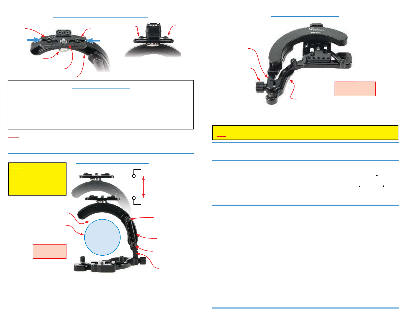
Adjusting the fl ash rotator height
The fl ash rotator is adjustable to work with short or tall cameras.
Adjust by loosening the upright screw, then position the rotator to be centered around the lens of the camera.
After desired position of rotator is set, lock upright screw using the 1/8” Allen wrench provided with bracket.
Note:
- Rotating without equal space around lens may cause damage to the lens or bracket.
- The leg must be completely folded in or out to rotate fl ash to avoid damage to the bracket.
Lens outside diameter
Position rotator
for equal space
around lens
Equal space around lens
Attach cord with ß ash screw
(do not tighten completely)
Slide one anti-twist to cord
(tighten anti-twist screw)
Slide other anti-twist to cord
(tighten anti-twist screw)
Tighten ß ash screw to cord
Attach cord (reversed) with ß ash screw
(do not tighten completely)
Slide left anti-twist to cord
(tighten anti-twist screw)
Remove cord and install normal
Slide right anti-twist to cord
(tighten anti-twist screw)
Tighten ß ash screw to cord
Flash rotator base
Upright
Height Adjustment
Note:
Before using the bracket with
camera attached, make sure
all screws are tighened. If not
tightened, the camera may be
damaged
.
RF-WT
Locking shoe mount with anti-twist for
wireless ß ash operation
WFM-2
Locking shoe mount with anti-twist for
wireless transmitters
RF-CB
Bottom tripod quick release plate
(Custom Brackets style)
Optional Accessories - Sold Separately
Attaching the bracket to a tripod or monopod
Attach the RF-PRO to a tripod / monopod’s 1/4”-20 mounting stud and tighten until fi rmly attached.
RF-C1
Connector for Spider Camera Holster
™
- Carry Speed
™
RF-C2
Connector for Black Rapid
™
ConnectR
RF-C3
Connector for Sun Sniper
™ -
Custom SLR
™ -
Joby
™
Folding the bracket for storage
Remove your camera and fl ash prior to storage. It is not necessary to remove a fl ash cord if attached to the fl ash
mounting plate. Loosen the upright lock knob and rotate upright backward to lower until fl at. Fold in the leg.
The upright knob may be tightened when the bracket is in the storage (fl at) position. The upright lock knob
must
be loosened prior to rotating the upright or damage may occur and warranty will be void.
Upright lock knob
Bracket in
storage position
Fold-out leg
Upright
Repair
Repair service is available by returning the RF-PRO (shipping prepaid) to Custom Brackets. All returns must include a return authorization
(RA) number (contact Custom Brackets to obtain), letter explaining the problem, and a copy of the sales receipt. A repair cost will be issued
and must be approved prior to any repairs. Shipping charges are the responsibility of the customer.
Maintenance
The only maintenance necessary on the RF-PRO is to clean the inside track of the rotator (back side) periodically with a clean cloth and
WD-40 to remove any dust or dirt that may have accumulated to keep it working at it’s best. The rotation tension is factory set. Attempting
to adjust the tension will void the warranty and may result in damage to the camera, lens or
ßash.

Other Custom Brackets Camera Accessories manuals

Custom Brackets Yuri Arcurs SteadyPod User manual

Custom Brackets

Custom Brackets Yuri Arcurs SteadyPod User manual

Custom Brackets RF-PRO M User manual

Custom Brackets

Custom Brackets RF-PRO M User manual

Custom Brackets Tilt Head CB User manual

Custom Brackets

Custom Brackets Tilt Head CB User manual

Custom Brackets RF-PRO AS User manual

Custom Brackets

Custom Brackets RF-PRO AS User manual

Custom Brackets HDV CAGE KIT User manual

Custom Brackets

Custom Brackets HDV CAGE KIT User manual

Custom Brackets CB Gimbal Basic User manual

Custom Brackets

Custom Brackets CB Gimbal Basic User manual

Custom Brackets Digital PRO-M User manual

Custom Brackets

Custom Brackets Digital PRO-M User manual

Popular Camera Accessories manuals by other brands

Worx WX876L user manual

Worx

Worx WX876L user manual

Hugyfot Vision Xs user manual

Hugyfot

Hugyfot Vision Xs user manual

Godox SL Series instruction manual

Godox

Godox SL Series instruction manual

Manfrotto MS0490C user manual

Manfrotto

Manfrotto MS0490C user manual

Ikan ELE-A7S-C quick start guide

Ikan

Ikan ELE-A7S-C quick start guide

SIRUI A100B user manual

SIRUI

SIRUI A100B user manual

Duracell Lithium Coin Battery IEC ANSI Specifications

Duracell

Duracell Lithium Coin Battery IEC ANSI Specifications

VMB TE - 071P operating instructions

VMB

VMB TE - 071P operating instructions

Vocas BP-19 MKII user manual

Vocas

Vocas BP-19 MKII user manual

dji RS 3 PRO user manual

dji

dji RS 3 PRO user manual

Nikon MC-EU1 instruction manual

Nikon

Nikon MC-EU1 instruction manual

Moza Slypod quick start guide

Moza

Moza Slypod quick start guide

COMBA CPBBUV1-48055-UL Quick installation guide

COMBA

COMBA CPBBUV1-48055-UL Quick installation guide

Miller 1576 Operator's manual

Miller

Miller 1576 Operator's manual

Belkin DIGITAL CAMERA LINK user guide

Belkin

Belkin DIGITAL CAMERA LINK user guide

Sony VCT-550RM operating instructions

Sony

Sony VCT-550RM operating instructions

KATA dps 123-GO-30 manual

KATA

KATA dps 123-GO-30 manual

Ikan BMC-PWR-BC quick start guide

Ikan

Ikan BMC-PWR-BC quick start guide

manuals.online logo
manuals.online logoBrands
  • About & Mission
  • Contact us
  • Privacy Policy
  • Terms and Conditions

Copyright 2025 Manuals.Online. All Rights Reserved.