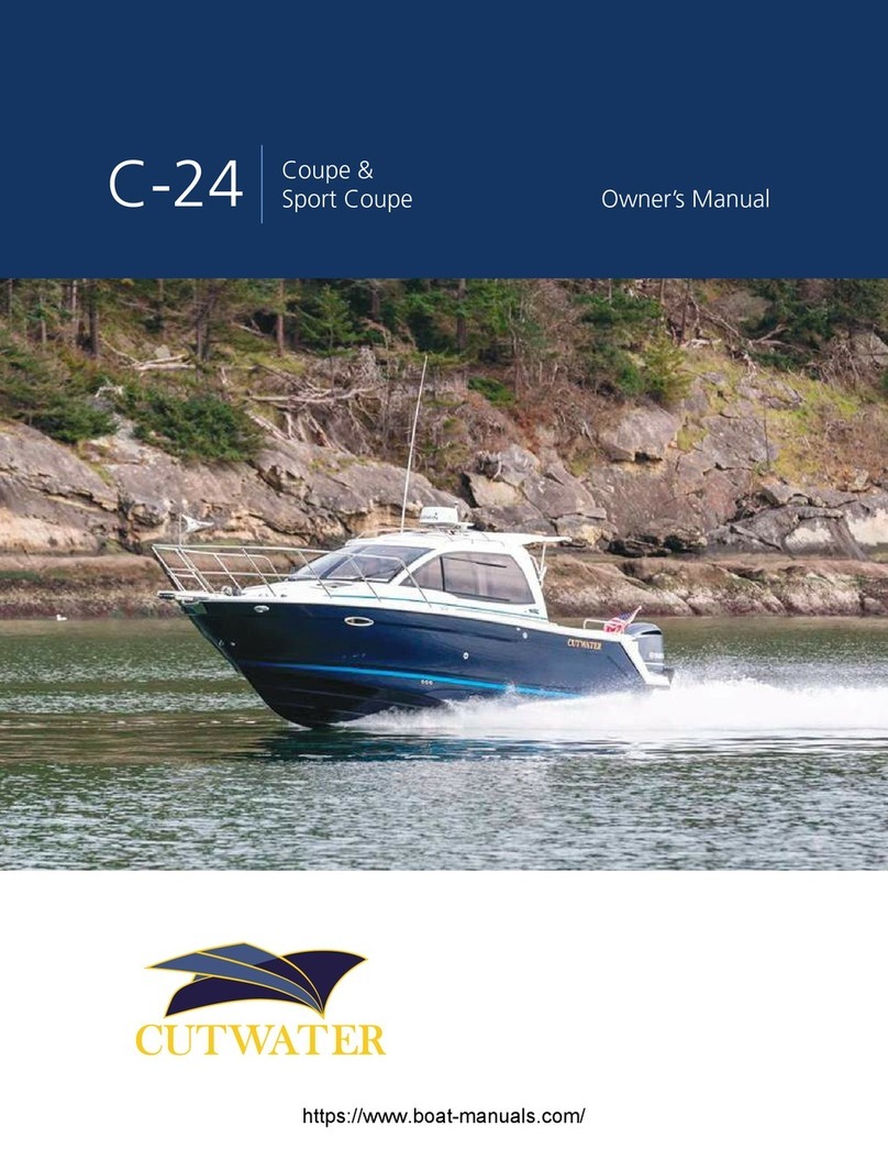
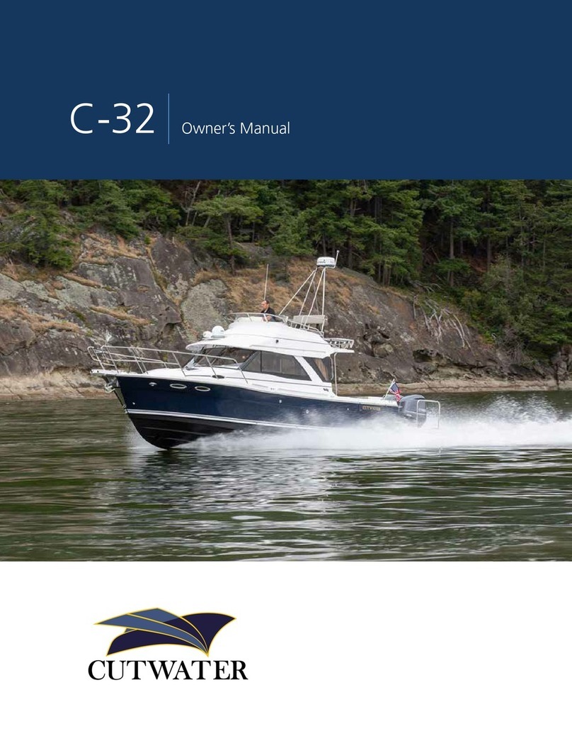
Cutwater 30 User manual

CUTWATER 30
OWNERS MANUAL

TABLE OF CONTENTS
2
Table Of Contents ........................................................................................................ 2
Congratulations ........................................................................................................... 3
Safety .......................................................................................................................... 3
Symbol Glossary ........................................................................................................... 4
Specifications (Subject To Change Without Notice) .................................................................. 5
Equipment Location ..................................................................................................... 6
Starboard Fittings .................................................................................................. 6
Port Fittings ........................................................................................................... 7
Main Cabin Top Deck Components ....................................................................... 8
Stern Components ................................................................................................. 9
Fuse Location & Values .......................................................................................... 10
Main Cabin And Cockpit Lights ............................................................................. 12
Battery Compartment ............................................................................................ 13
Power Distribution Center ..................................................................................... 14
AC Distribution Panel, Rotary Switch & DV Volt Meter ............................................ 15
Fuel System, Engine, Generator & Webasto Furnace .............................................. 16
Webasto Furnace .................................................................................................. 17
Air Conditioning System ........................................................................................ 18
Generator ............................................................................................................. 19
Solar Panel ............................................................................................................ 20
Shore Power .......................................................................................................... 21
Closed Engine Cooling System .............................................................................. 22
Sea Strainer System ............................................................................................... 23
Raw Water Wash Down ......................................................................................... 24
Fresh Water Plumbing System ................................................................................ 25
Shower Sump ........................................................................................................ 26
Bilge Pump System ................................................................................................ 27
Waste System ........................................................................................................ 28
Mast Set Up And Takedown .................................................................................. 29
Cutwater 30 Wiring Schematic (Acc. 1) ................................................................. 30
Cutwater 30 Wiring Schematic (Acc. 2) ................................................................. 31
Cutwater 30 Wiring Schematic (Acc. 3) ................................................................. 32
Cutwater 30 Wiring Schematic (Lighting) .............................................................. 33
Cutwater 30 Wiring Schematic (P.D.P.) ................................................................... 34
Working Deck .............................................................................................................. 35
Care And Maintenance ................................................................................................ 36
Example Of A Preparation For The Road Checklist .................................................. 36
Example Of A Spring Pre-Launch Checklist ............................................................. 37
Example Of Winter Storage Checklist .................................................................... 38
Reference Material ....................................................................................................... 39
Contacts ...................................................................................................................... 40
Notes ........................................................................................................................... 41

3
CONGRATULATIONS
The Cutwater family has a passion for boating. We are committed to continuous
process improvement in all areas that affect our customer’s satisfaction with our
products and providing great customer service.
SAFETY
Safety is always a concern at Cutwater. Please read all manuals to ensure that equip-
ment is used in a safe manner. We highly recommend attendance in a Coast Guard
approved boating safety course. Such courses are available from the Coast Guard
directly or from boating organizations. Owners should have annual inspections to
ensure that all safety equipment is current.

STD
OPT
SYMBOL GLOSSARY
4
Attention! – Important Operating or Maintenance Instructions
Attention! – Electrical Shock Hazard
Fresh Water
Black Water
Fuel
Standard Equipment
Optional Equipment
Hints

5
C30
C30 SPORT TOP
C30 COMMAND BRIDGE
SPECIFICATIONS
(Subject to Change Without Notice)
LOA molded ..................................................................................30’ - 0” 9.14 m
LOA rigged (with swim platform & pulpit) ......................................34’ – 4” 10.46 m
Bridge clearance (mast folded) .......................................................9’ - 9” 2.97 m
Height on trailer.............................................................................13’ - 2” 4.01 m
Beam.............................................................................................10’ - 0” 3.05 m
Draft..............................................................................................2’ - 5” .73 m
Fuel capacity..................................................................................180 U.S. Gal 681.4 L
Water capacity...............................................................................80 U.S. Gal 302.8 L
Holding tank capacity ....................................................................40 U.S. Gal 151.4 L
Weight dry.....................................................................................10,200 lbs 4,626 kg
Engine ...........................................................................................D6 Volvo 435 H.P. Diesel
LOA molded ..................................................................................30’ - 0” 9.14 m
LOA rigged (with swim platform & pulpit) ......................................34’ – 4” 10.46 m
Bridge clearance (bridge folded).....................................................9’ - 9” 2.97 m
Height on trailer.............................................................................13’ - 2” 4.01 m
Beam.............................................................................................10’ - 0” 3.05 m
Draft..............................................................................................2’ - 5” .73 m
Fuel capacity..................................................................................180 U.S. Gal 681.4 L
Water capacity...............................................................................80 U.S. Gal 302.8 L
Holding tank capacity ....................................................................40 U.S. Gal 151.4 L
Weight dry.....................................................................................10,980 lbs 4,980 kg
Engine ...........................................................................................D6 Volvo 435 H.P. Diesel

EQUIPMENT LOCATION
6
STARBOARD FITTINGS
1 2 3 4 5 6 7 8 10 11
Keep all vents, drains and exhausts clear of any obstructions
to ensure proper performance of each system.
9
➊ Aft Bilge
➋ Forward Bilge
➌ Keel Drain Plug
➍ Diesel Fill
➎ Fuel Vent
➏ Waste Vent
➐ Waste Pump Out
➑ Head Sink Drain
➒ Macerator
➓ Docking Lights
Bow Thruster
➓
➌
➍
➎➏
➊➋➑
➐
➒

7
PORT FITTINGS
1 2 3 5 6 7 9 10
4 8 11
Keep all vents, drains and exhausts clear of any obstructions
to ensure proper performance of each system.
➊ Docking Lights
➋ Anchor Locker Drain
➌ Shower Sump
➍ Air Conditioner Drain
➎ Galley Sink Drain
➏ Freshwater Fill
➐ Freshwater Vent
➑ Generator Exhaust
➒Bow Thruster
➓Engine Exhaust
Webasto Heater Exhaust
➊
➋
➑
➒➓
➐
➌➍➍ ➎
➏

MAIN CABIN TOP DECK COMPONENTS
8
1 2 3 6 7
4 5 8
➊ Searchlight
➋ Horn
➌ Digital TV Antennae
(satellite ready - not included)
➍ Radar
➎ XM-Weather Antennae
➏ Anchor Light
➐ Port Navigation Light
➑ Solar Panel
Sedan
Sport Top
Command Bridge
➊
➊
➊
➋
➋
➋
➌
➌
➌
➎
➎
➎
➏
➏
➏
➍
➍
➍
➐
➐
➐
➑
➑
➑

9
STERN COMPONENTS
1 2 4 5 6 7 8 9 10
➊ Courtesy Lights
➋ Cockpit Drains
➌ Underwater Lights
➍ Prop Zinc
➎ Stern Thruster
➏ Swim Platform Retractable Ladder
➐ Trim Tabs
➑ Prop
➒ Rudder
➓ Dunnage Box
➊
➋ ➋
➎
➌➌
➏
➐➐
➑
➒
➊
3
➓
➍

FUSE LOCATION & VALUES
10
The dash fuse blocks are located behind the hinged mirror located inside of the bathroom.
Fuses are automotive blade type and all values are shown in amps.
Dash Fuse Block #1 Dash Fuse Block #2
Navigation
PANEL (4 Switch)
Bilge Pump (#1)
LPG Controller
VHFTV #1 Head Lights
PANEL (8 Switch)
Bilge Pump (#2)
Seat Sensor
HeaterTV #2 Wine Cooler
PANEL (8 Switch)
Bilge Alarm
StereoTV Antenna 12V Outlet (V-Berth)
Head Stereo AmpLight Switch (V-berth) Shower Pump
Trim Tabs12V Outlet (Dinette) 12V Outlet (Dash)
Screen (Option)
Radar (Option)
Screen (Option)Webasto Heater
AIS (Option)
Network (Option)

11
Thruster Battery
Engine Battery
FUSE LOCATIONS AND VALUES CONTINUED
These four blocks and fuses are located in the Quarter Berth aft storage area.
The bilge pumps operate automatically with electronic float switches when all switches
and breakers are in the OFF position.
However, the BILGE PUMP and BILGE PUMP2 will run continuously once their switches are placed
in the on position. Monitor the outflow accordingly. Do not run when dry.
Thruster Battery and Engine Battery fuse blocks are energized even when the battery switch is off.
Bilge Pump (#1)
LPG Controller
CO Monitor (#1)
Volt Meter (Battery #2)
Bilge Pump (#2)
Seat Sensor
Optional: Bridge
12V Outlet (Bridge)
Switch Panel (Bridge)
Screen (Option)
CO Monitor (#2)
Hatch Switch
Bilge Alarm Volt Meter (Battery #3)
PDP
Downrigger (Star) Autopilot Pump
Downrigger (Port) Washdown Pump
12V Outlet (Qtr Berth) Fresh Water Pump
Refrigerator Cabin Lights
Refrigerator (Aft) Misc. Lights
Panel (4 Switch) Spotlight

12
MAIN CABIN AND COCKPIT LIGHTS
Courtesy
Light Switch
V-Berth
Light Switch
Cabin
Light Switch
Head
Light Switch
Under Matress
Light Switch
➊ Courtesy Lights ✓
➋ Deck Aft Lights ✓
➌ Cabin Lights ✓
➍ V-Berth Lights ✓
➎ V-Berth Bed Lights ✓
➏ Head Lights ✓
➐ Under Matress Lights ✓
Courtesy
Light Switch
V-Berth
Light Switch
Cabin
Light Switch
Head
Light Switch
Chart
Light Switch
➊ Courtesy Lights ✓
➋ Deck Aft Lights ✓
➌ Chart Lights ✓
➍ Cabin Lights ✓
➎ V-Berth Lights ✓
➏ V-Berth Bed Lights ✓
➐ Head Light ✓
➌ Switch
➌ Dimmer
Switch ➏ Switch
➊ ➋ Switch
➏
➎
➎
➍
➍
➍
➍
➍ ➍
➎ Switch
➋
➋
➊
➊
➊
➊
➊➊
➌ Switch
➋
➌
➌ ➌
➌
➌
➌
➌
➌
➋
➏
➏
➌
➐ ➐

13
BATTERY COMPARTMENT
13
(4) House Batteries, (1) Engine Battery, (1) Thruster Battery (generator shares), Inverter/Charger
Inverter Fuse (150 AMP), Inverter/Charger Cutoff Switch (Group 27, 1 each - start battery, 5 each
- deep cycle batteries)
Inverter
Switch
Inverter Fuse
Inverter/
Charger 3
2
11
11
Batteries
1= House
2= Engine
3= Thruster
AGM (4) House Batteries, (1) Engine Battery, (1) Thruster Battery (generator shares), Inverter/
Charger Inverter Fuse (150 AMP), Inverter/Charger Cutoff Switch (Group 31, 6 each - start/deep
cycle batteries)
AGM batteries required for boats with solar panel.

POWER DISTRIBUTION CENTER
14
The parallel switch should always remain in the off position. While in the on position, the house
and engine batteries will be combined as one for emergency start only.
Located in the starboard cockpit step.
House, Engine, Thrusters and Crossover switch
HOUSE
SWITCH
ENGINE
SWITCH
BOW
THRUSTER
SWITCH
PARALLEL
SWITCH
STERN
THRUSTER
SWITCH
50A FUSE
BLOCK
BREAKER
150A
DASH
BREAKER
CHARGING
RELAY
CHARGING
RELAY
STERN THRUSTER
250 AMP ANL FUSE
BOW THRUSTER
250 AMP ANL FUSE
If the house bank drops below 10.8v you must reset the charging relay by switching on the
parallel while the engine is running.

15
AC DISTRIBUTION PANEL, ROTARY SWITCH
& DC VOLT METER
AC Rotary Selector Switch. Available with Generator
The AC Rotary Switch Selector Switch will determine which source of incoming 120 Volt power
to use for your AC Distribution Panel.
AC Distribution Panel
with optional Air Conditioning
and/or Generator
Inverter Bus
Inverter Bus
AC Distribution Panel
Standard
15A MICROWAVE
15A
15A
25A
GALLEY
OUTLETS
OUTLETS
FORWARD
SALON
OUTLETS
20A
15A
25A
15A ACCESSORY
AIR
RELAY
AFT
AIR
FWD
AIR
15A
15A
15A
15A ACCESSORY
ACCESSORY
ACCESSORY
ACCESSORY
25A ACCESSORY
15A
25A
WATER
HEATER
20A
ICE
MAKER
COOK
TOP
OVEN
15A MICROWAVE
15A
15A
25A
GALLEY
OUTLETS
OUTLETS
FORWARD
SALON
OUTLETS
30A
ELCI
AC MAIN
1
15A
20A
15A
15A ACCESSORY
WATER
HEATER
ICE
MAKER
ACCESSORY
30A
ELCI
AC MAIN
2
30A
ELCI
AC MAIN
1
DC VOLTS
DC VOLTS
AC VOLTS
AC VOLTS
BATTERY
BANK
BATTERY
BANK
1
2
3
1
2
3
12V BATTERY MONITOR
1= House
2= Engine
3= Thruster
WATER
FE

FUEL SYSTEM, ENGINE, GENERATOR &
WEBASTO FURNACE
16
D6 Volvo 435 H.P. Diesel
Generator 5.0 KW Onan, Webasto Furnace
There is a secondary on engine fuel filter that is not shown on this drawing. You will be able to
find information about this filter in the diesel engine manual supplied with your boat.
Fuel shutoff and all fuel filters are located on the Fuel Management Board,
port side of engine room.
Fuel management board
Fill
Webasto P
/
Webasto P/Webasto P
V
Engine pick up
Engine return
Vent
Generator return (opt.)
Generator pick up (opt.)
Engine
Generator
feed Generator
shutoff
(off position)
Engine
shutoff
(off position)
Generator
filter
Engine
filter
Engine
feed

17
WEBASTO FURNACE
Webasto furnace is located under access panel below range.
The controller is located at the quarter berth power management center.
The pump is in the salon floor hatch compartment.
Webasto Furnace
Fuel Pump / Filter
Heat Vent
Heat Vent
Exhaust

18
AIR CONDITIONING SYSTEM
Air Conditioning System
Air Conditioner Pump
Air Conditioner Sea Strainer
Air Conditioner Thru-Hull
Raw Water Discharge
Air Conditioner V-Berth 12kw
Air Conditioner Dislpay
located at Power Management
Control Center
Shower Sump Box
Condensate Drain
Air Conditioner
Dislpay V-Berth
Air Conditioner Salon 16kw
Access from mid cabin

19
GENERATOR
Generator 5.0 KW Onan
*Generator will start off of thruster battery #3
Generator Fuel ReturnGenerator Fuel Pickup
Generator
Exhaust
Water Lock
Silencer
Generator Fuel Filter
Fuel Shut Off

20
SOLAR PANEL
Solar panel 140 watt, with control panel
• The solar panel is designed to provide charging to the house & engine batteries. 90% of its
charge is dedicated to the house battery and 10% is dedicated to the engine battery.
• The green light on the solar display indicates proper operation.
• The solar controller is located at the power management control center.
• Boats with solar panel require AGM battery upgrade.
• The solar controller is located at the power management control center.
• Boats with solar panel require AGM battery upgrade.
• The solar controller is located at the power management control center.
• Boats with solar panel require AGM battery upgrade.
Engine Battery
Thruster Battery
Solar Panel
Solar Controller
House Batteries
3
2
1
1
1
1
Table of contents
Other Cutwater Boat manuals
Popular Boat manuals by other brands

Teledyne Oceanscience
Teledyne Oceanscience High Speed User's guide and warranty

Sport Boats
Sport Boats Dolphin 8.8' Air Floor Owner's operating manual & safety information

Trophy
Trophy 1703CC owner's manual

Baja
Baja Outlaw 25 owner's manual

Sienne
Sienne Jeanneau International 50 Operation manual

Pelican
Pelican IPVUEKJP12-2 Assembly instructions