manuals.online logo
Brands
  1. Home
  2. •
  3. Brands
  4. •
  5. CyberData
  6. •
  7. Adapter
  8. •
  9. CyberData Singlewire Paging Adapter Quick start guide

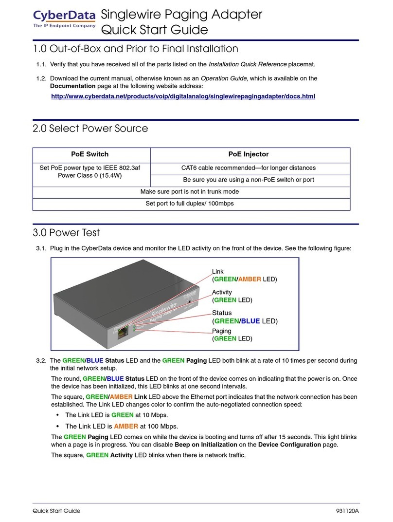
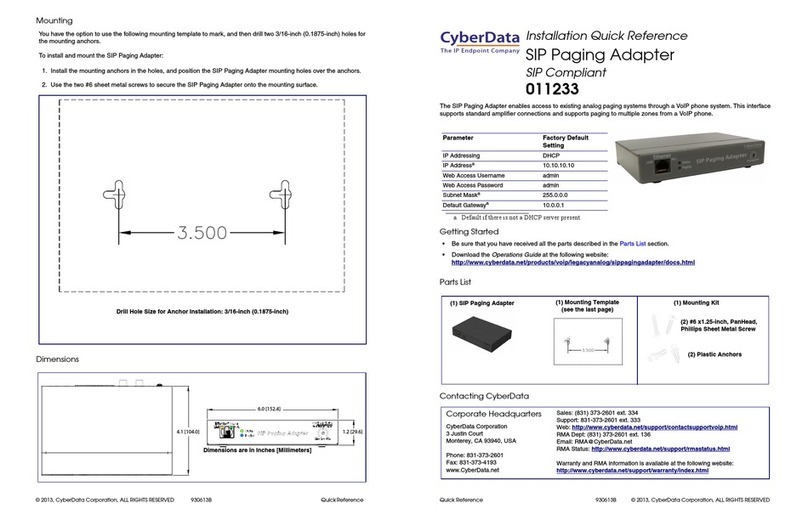
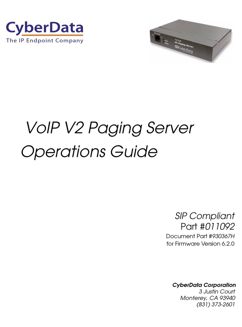
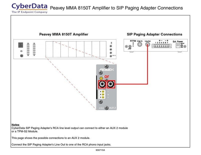
CyberData Singlewire Paging Adapter Quick start guide

Other manuals for Singlewire Paging Adapter

2

Other CyberData Adapter manuals

CyberData 11233 User manual

CyberData

CyberData 11233 User manual

CyberData 11233 Manual

CyberData

CyberData 11233 Manual

CyberData SIP PAGING ADAPTER Quick start guide

CyberData

CyberData SIP PAGING ADAPTER Quick start guide

CyberData 11280 User manual

CyberData

CyberData 11280 User manual
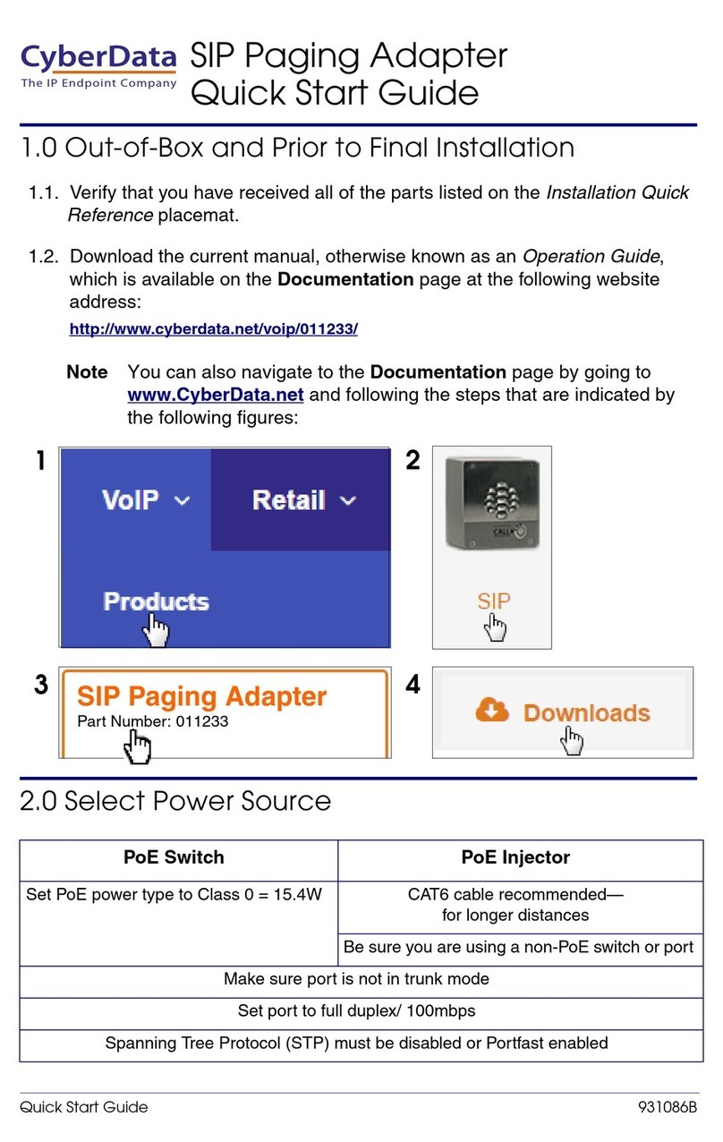
CyberData VoIP V2 User manual

CyberData

CyberData VoIP V2 User manual

CyberData VoIP V2 User manual

CyberData

CyberData VoIP V2 User manual

CyberData 11280 Manual

CyberData

CyberData 11280 Manual

CyberData 11024 User manual

CyberData

CyberData 11024 User manual

CyberData 11280 User manual

CyberData

CyberData 11280 User manual

CyberData 11233 User manual

CyberData

CyberData 11233 User manual

CyberData 11233 Manual

CyberData

CyberData 11233 Manual

CyberData Singlewire Paging Adapter Instruction manual

CyberData

CyberData Singlewire Paging Adapter Instruction manual

CyberData 011280C User manual

CyberData

CyberData 011280C User manual

CyberData 11107 Manual

CyberData

CyberData 11107 Manual

CyberData SIP PAGING ADAPTER Instruction manual

CyberData

CyberData SIP PAGING ADAPTER Instruction manual

CyberData 11233 User manual

CyberData

CyberData 11233 User manual
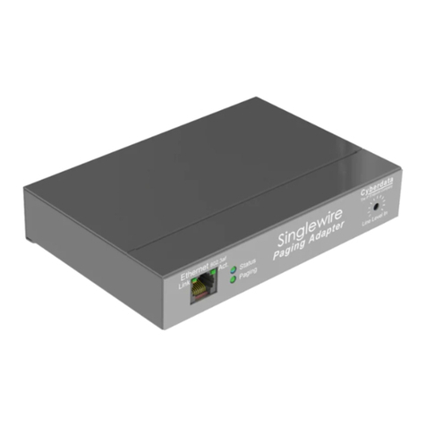
CyberData Singlewire Paging Adapter Instruction manual

CyberData

CyberData Singlewire Paging Adapter Instruction manual

CyberData 11233 User manual

CyberData

CyberData 11233 User manual

Popular Adapter manuals by other brands

Mini Gadgets BB2Outlet user manual

Mini Gadgets

Mini Gadgets BB2Outlet user manual

LSI LSISAS3442E-R Quick installation guide

LSI

LSI LSISAS3442E-R Quick installation guide

Moeller BBA -16 Series installation instructions

Moeller

Moeller BBA -16 Series installation instructions

Acer MWA3 quick start guide

Acer

Acer MWA3 quick start guide

Connect Tech ADG095 user guide

Connect Tech

Connect Tech ADG095 user guide

cable matters 604002 user manual

cable matters

cable matters 604002 user manual

Solwise PL-85PEW Easy start

Solwise

Solwise PL-85PEW Easy start

HP Photosmart 7100 user guide

HP

HP Photosmart 7100 user guide

HP E2494A installation guide

HP

HP E2494A installation guide

StarTech.com USB150WN1X1 quick start guide

StarTech.com

StarTech.com USB150WN1X1 quick start guide

Lindy 43198 user manual

Lindy

Lindy 43198 user manual

A&D AD-8527 instruction manual

A&D

A&D AD-8527 instruction manual

Motorola WU830G user guide

Motorola

Motorola WU830G user guide

Hawking HUF2 Specifications

Hawking

Hawking HUF2 Specifications

Allen-Bradley E3 Plus installation instructions

Allen-Bradley

Allen-Bradley E3 Plus installation instructions

Trust BT-2210Tp manual

Trust

Trust BT-2210Tp manual

HP NC7170 overview

HP

HP NC7170 overview

Uconnect BLE-485C user manual

Uconnect

Uconnect BLE-485C user manual

manuals.online logo
manuals.online logoBrands
  • About & Mission
  • Contact us
  • Privacy Policy
  • Terms and Conditions

Copyright 2025 Manuals.Online. All Rights Reserved.

931022A
Connecting a CyberData Singlewire Paging Adapter
to a Bogen PCM2000 Zone Paging System
The IP Endpoint Company
931022A
PCM
TIM
POWER
TONE
VOLUME
BGM SRC
VOLUME
GND ST
IN
RT
BGM
SRC
NIGHT
RING
TEL
LINE
OVER
RIDE
NC
COM
NO
NC
COM
NO
RLY
ONE
RLY
TWO
S1
S2
S3
S4
S5
S6
S7
TEL
INT
SEL
0 1
S1
S2
S3
S4
S5
S6
S7
TEL
INT
SEL
0 1
1 - Not used
2 - Contact Closure
3 - Dry audio (R)
4 - Dry audio (T)
5 - Contact Closure
6 - Not used
Bogen PCM2000 Zone Paging System with Old PCMTIM to Singlewire Paging Adapter Connections—Contact Closure Configuration
Bogen PCMTIM Module Configuration Singlewire Paging Adapter Connections
+-+
-
Notes
CyberData Singlewire Paging Adapter's Page Port output connects to the
TEL LINE input on the PCMTIM module using an RJ11 modular connec-
tor. Pins 2, 3, 4, and 5 of the RJ11 modular connector will be used for this
configuration.
Power off the PCMTIM. Set the TEL INT SEL switches per the above dia-
gram for a Page Port/Contact Closure configuration. Page activation
occurs upon contact closure.
It will be necessary to use the dry relay contacts for contact closure. Be
sure to check the Enable relay on local audio option on the Device
Configuration page of the web interface.
s
Page Port Output Connections
Pin Description
1 Fault Sense Input (Common).
2 Fault Sense Input (Sense).
3 Positive 600-Ohm Audio Outputa
a.The 600-Ohm audio output of the page port is
also suited for interfaces with lower input
impedances.
4 Negative 600-Ohm Audio Outputa
5 Audio Ground Reference.
6 Relay Contact - Commonb
b.1 Amp at 30 VDC for continuous loads.
7 Relay Contact - Normally Openb
TEL LINE
The IP Endpoint Company
931022A
1 - Not used
2 - Contact Closure
3 - Dry audio (R)
4 - Dry audio (T)
5 - Contact Closure
6 - Not used
PCM
TIM
POWER
TONE
VOLUME
BGM SRC
VOLUME
GND ST
IN
RT
BGM
SRC
NIGHT
RING
TEL
LINE
OVER
RIDE
NC
COM
NO
NC
COM
NO
RLY
ONE
RLY
TWO
S1
S2
S3
S4
S5
S6
S7
TEL
INT
SEL
0 1
POWER
- 1.5A
OUT
RT
GND
AUX
GND
S1
S2
S3
S4
0 1
SYS
ID
RUN
PROGRAM
DATA
LINK
12 VDC
1.5A
-
IN
RT
RT
IN
RT
IN
EM/SC
+ 12VDC
BOGEN
PA
LPBGM
PA
HPBGM
+
POWER
RD COM
+
-
RD A
RD B
ZONE A
ZONE B
ZONE C
OFF ON
TALKBACK
RT
IN
RD C
LOCAL
BGM
ZONE A
+
-
ZONE B
+
-
ZONE C
LPBGM
VOLUME
LO PWR
HI PWR
OUTPUT
BGM
OUT IN
PCM
ZPM
PCM
CPU
PBX
PAGING
PORT
T
R
+
-
PCM PS2
RT
70V COM
BOGEN PAGING
AMPLIFIER
CONTACT
CLOSURE
ZONE A
ZONE B
ZONE C
GLOBL BGM
ZONE C
ZONE B
ZONE A
S1
S2
S3
S4
S5
S6
S7
TEL
INT
SEL
0 1
Bogen PCM2000 Zone Paging System with old PCMTIM to Singlewire Paging Adapter Connections—Contact Closure Configuration
Bogen PCM2000 Application Configuration Singlewire Paging Adapter Connections
+-+
-
s
Page Port Output Connections
Pin Description
1 Fault Sense Input (Common).
2 Fault Sense Input (Sense).
3 Positive 600-Ohm Audio Outputa
a.The 600-Ohm audio output of the page port is
also suited for interfaces with lower input
impedances.
4 Negative 600-Ohm Audio Outputa
5 Audio Ground Reference.
6 Relay Contact - Commonb
b.1 Amp at 30 VDC for continuous loads.
7 Relay Contact - Normally Openb
TEL LINE
Notes
This configuration requires PCMTIM, PCMCPU, and PCMZPM modules assembled in this respective order, from left to right.
Do not connect the PCMPS2 power supply to the PCMCPU until the module switch settings and wiring connections have
been completed. Contact Bogen Technical Support for assistance with Bogen PCM2000 configurations.
The IP Endpoint Company
931022A
PCM
TIM
POWER
TONE
VOLUME
BGM SRC
VOLUME
GND ST
IN
RT
BGM
SRC
NIGHT
RING
TEL
LINE
OVER
RIDE
NC
COM
NO
NC
COM
NO
RLY
ONE
RLY
TWO
S1
S2
S3
S4
S5
S6
S7
TEL
INT
SEL
0 1
S1
S2
S3
S4
S5
S6
S7
TEL
INT
SEL
0 1
1 - Not used
2 - Not used
3 - Dry audio (R)
4 - Dry audio (T)
5 - Not used
6 - Not used
Bogen PCM2000 Zone Paging System with old PCMTIM to Singlewire Paging Adapter Connections—VOX Configuration
Bogen PCMTIM Module Configuration Singlewire Paging Adapter Connections
+-+
-
Notes
CyberData Singlewire Paging Adapter’s Page Port output connects to the
TEL LINE input on the PCMTIM using an RJ11 modular connector. Only
pins 3 and 4 of the RJ11 modular connector will be used for this configu-
ration.
Power off the PCMTIM. Set the TEL INT SEL switches per the above
diagram for a Page Port/Vox configuration. Page activation occurs on the
first DTMF tone rather than contact closure.
s
Page Port Output Connections
Pin Description
1 Fault Sense Input (Common).
2 Fault Sense Input (Sense).
3 Positive 600-Ohm Audio Outputa
a.The 600-Ohm audio output of the page port is
also suited for interfaces with lower input
impedances.
4 Negative 600-Ohm Audio Outputa
5 Audio Ground Reference.
6 Relay Contact - Commonb
b.1 Amp at 30 VDC for continuous loads.
7 Relay Contact - Normally Openb
TEL LINE
The IP Endpoint Company
931022A
PCM
TIM
POWER
TONE
VOLUME
BGM SRC
VOLUME
GND ST
IN
RT
BGM
SRC
NIGHT
RING
TEL
LINE
OVER
RIDE
NC
COM
NO
NC
COM
NO
RLY
ONE
RLY
TWO
S1
S2
S3
S4
S5
S6
S7
TEL
INT
SEL
0 1
POWER
- 1.5A
OUT
RT
GND
AUX
GND
S1
S2
S3
S4
0 1
SYS
ID
RUN
PROGRAM
DATA
LINK
12 VDC
1.5A
-
IN
RT
RT
IN
RT
IN
EM/SC
+ 12VDC
BOGEN
PA
LPBGM
PA
HPBGM
+
POWER
RD COM
+
-
RD A
RD B
ZONE A
ZONE B
ZONE C
OFF ON
TALKBACK
RT
IN
RD C
LOCAL
BGM
ZONE A
+
-
ZONE B
+
-
ZONE C
LPBGM
VOLUME
LO PWR
HI PWR
OUTPUT
BGM
OUT IN
PCM
ZPM
PCM
CPU
+
-
PCM PS2
RT
70V COM
BOGEN PAGING
AMPLIFIER
ZONE A
ZONE B
ZONE C
GLOBL BGM
ZONE C
ZONE B
ZONE A
S1
S2
S3
S4
S5
S6
S7
TEL
INT
SEL
0 1
1 - Not used
2 - Not used
3 - Dry audio (R)
4 - Dry audio (T)
5 - Not used
6 - Not used
Bogen PCM2000 Zone Paging System with old PCMTIM to Singlewire Paging Adapter Connections—VOX Configuration
Bogen PCM2000 Application Configuration Singlewire Paging Adapter Connections
+-+
-
Notes
This configuration requires PCMTIM, PCMCPU, and PCMZPM modules assembled in this respective order, from left to
right. Do not connect the PCMPS2 power supply to the PCMCPU until the module switch settings and wiring connections
have been completed. Contact Bogen Technical Support for assistance with Bogen PCM2000 configurations.
s
Page Port Output Connections
Pin Description
1 Fault Sense Input (Common).
2 Fault Sense Input (Sense).
3 Positive 600-Ohm Audio Outputa
a.The 600-Ohm audio output of the page port is
also suited for interfaces with lower input
impedances.
4 Negative 600-Ohm Audio Outputa
5 Audio Ground Reference.
6 Relay Contact - Commonb
b.1 Amp at 30 VDC for continuous loads.
7 Relay Contact - Normally Openb
TEL LINE
The IP Endpoint Company
931022A
1 - Not used
2 - Contact Closure
3 - Dry audio (R)
4 - Dry audio (T)
5 - Contact Closure
6 - Not used
TRUNK/PAGE PORT
Bogen PCM2000 Zone Paging System with New PCMTIM to Singlewire Paging Adapter Connections—Contact Closure Configuration
Bogen PCMTIM Module Configuration
Singlewire Paging Adapter Connections
+-+
-
s
Page Port Output Connections
Pin Description
1 Fault Sense Input (Common).
2 Fault Sense Input (Sense).
3 Positive 600-Ohm Audio Outputa
a.The 600-Ohm audio output of the page port is
also suited for interfaces with lower input
impedances.
4 Negative 600-Ohm Audio Outputa
5 Audio Ground Reference.
6 Relay Contact - Commonb
b.1 Amp at 30 VDC for continuous loads.
7 Relay Contact - Normally Openb
Notes
CyberData Singlewire Paging Adapter’s Page Port output connects to the TRUNK/PAGE PORT input on the PCMTIM
module using an RJ11 modular connector.
Power off the PCMTIM. Set the DIP switches to CC (bottom position) and P/P (middle position) as shown above for a
Page Port/Contact Closure configuration. Page activation occurs upon contact closure.
It will be necessary to use the dry relay contacts for contact closure. Be sure to check the Enable relay on local
audio option on the Device Configuration page of the web interface.
The IP Endpoint CompanyThe IP Endpoint Company
931022A
1 - Not used
2 - Contact Closure
3 - Dry audio (R)
4 - Dry audio (T)
5 - Contact Closure
6 - Not used
TRUNK/PAGE PORT
POWER
- 1.5A
OUT
RT
GND
AUX
GND
S1
S2
S3
S4
0 1
SYS
ID
RUN
PROGRAM
DATA
LINK
12 VDC
1.5A
-
IN
RT
RT
IN
RT
IN
EM/SC
+ 12VDC
BOGEN
PA
LPBGM
PA
HPBGM
+
POWER
RD COM
+
-
RD A
RD B
ZONE A
ZONE B
ZONE C
OFF ON
TALKBACK
RT
IN
RD C
LOCAL
BGM
ZONE A
+
-
ZONE B
+
-
ZONE C
LPBGM
VOLUME
LO PWR
HI PWR
OUTPUT
BGM
OUT IN
PCM
ZPM
PCM
CPU
+
-
PCM PS2
RT
70V COM
BOGEN PAGING
AMPLIFIER
ZONE A
ZONE B
ZONE C
GLOBL BGM
ZONE C
ZONE B
ZONE A
PBX
PAGING
PORT
T
R
CONTACT
CLOSURE
PCM
TIM
The IP Endpoint Company
Bogen PCM2000 Zone Paging System with New PCMTIM to Singlewire Paging Adapter Connections—Contact Closure Configuration
Bogen PCM2000 Application Configuration Singlewire Paging Adapter Connections
+-+
-
s
Page Port Output Connections
Pin Description
1 Fault Sense Input (Common).
2 Fault Sense Input (Sense).
3 Positive 600-Ohm Audio Outputa
a.The 600-Ohm audio output of the page port is
also suited for interfaces with lower input
impedances.
4 Negative 600-Ohm Audio Outputa
5 Audio Ground Reference.
6 Relay Contact - Commonb
b.1 Amp at 30 VDC for continuous loads.
7 Relay Contact - Normally Openb
Notes
This configuration requires PCMTIM, PCMCPU, and PCMZPM modules assembled in this respective order, from left to right.
Do not connect the PCMPS2 power supply to the PCMCPU until the module switch settings and wiring connections have
been completed. Contact Bogen Technical Support for assistance with Bogen PCM2000 configurations.
931022A
1 - Not used
2 - Not used
3 - Dry audio (R)
4 - Dry audio (T)
5 - Not used
6 - Not used
Bogen PCM2000 Zone Paging System with new PCMTIM to Singlewire Paging Adapter Connections—VOX Configuration
Bogen PCMTIM Module Configuration
Singlewire Paging Adapter Connections
+-+
-
s
Page Port Output Connections
Pin Description
1 Fault Sense Input (Common).
2 Fault Sense Input (Sense).
3 Positive 600-Ohm Audio Outputa
a.The 600-Ohm audio output of the page port is
also suited for interfaces with lower input
impedances.
4 Negative 600-Ohm Audio Outputa
5 Audio Ground Reference.
6 Relay Contact - Commonb
b.1 Amp at 30 VDC for continuous loads.
7 Relay Contact - Normally Openb
Notes
CyberData Singlewire Paging Adapter’s Page Port output connects to the TRUNK/PAGE PORT input on the PCMTIM
module using an RJ11 modular connector. Only pins 3 and 4 of the RJ11 modular connector will be used for this configu-
ration.
Power off the PCMTIM. Set the DIP switches to VX (top position) and P/P (middle position) as shown above for a Page
Port/Vox configuration. Page activation occurs on the first DTMF tone rather than contact closure.
The IP Endpoint Company
TRUNK/PAGE PORT
931022A
1 - Not used
2 - Not used
3 - Dry audio (R)
4 - Dry audio (T)
5 - Not used
6 - Not used
TRUNK/PAGE PORT
POWER
- 1.5A
OUT
RT
GND
AUX
GND
S1
S2
S3
S4
0 1
SYS
ID
RUN
PROGRAM
DATA
LINK
12 VDC
1.5A
-
IN
RT
RT
IN
RT
IN
EM/SC
+ 12VDC
BOGEN
PA
LPBGM
PA
HPBGM
+
POWER
RD COM
+
-
RD A
RD B
ZONE A
ZONE B
ZONE C
OFF ON
TALKBACK
RT
IN
RD C
LOCAL
BGM
ZONE A
+
-
ZONE B
+
-
ZONE C
LPBGM
VOLUME
LO PWR
HI PWR
OUTPUT
BGM
OUT IN
PCM
ZPM
PCM
CPU
+
-
PCM PS2
RT
70V COM
BOGEN PAGING
AMPLIFIER
ZONE A
ZONE B
ZONE C
GLOBL BGM
ZONE C
ZONE B
ZONE A
PCM
TIM
PBX
PAGING
PORT
T
R
Bogen PCM2000 Zone Paging System with New PCMTIM to Singlewire Paging Adapter Connections—VOX Configuration
Bogen PCM2000 Application Configuration Singlewire Paging Adapter Connections
+-+
-
s
Page Port Output Connections
Pin Description
1 Fault Sense Input (Common).
2 Fault Sense Input (Sense).
3 Positive 600-Ohm Audio Outputa
a.The 600-Ohm audio output of the page port is
also suited for interfaces with lower input
impedances.
4 Negative 600-Ohm Audio Outputa
5 Audio Ground Reference.
6 Relay Contact - Commonb
b.1 Amp at 30 VDC for continuous loads.
7 Relay Contact - Normally Openb
Notes
This configuration requires PCMTIM, PCMCPU, and PCMZPM modules assembled in this respective order, from left to
right. Do not connect the PCMPS2 power supply to the PCMCPU until the module switch settings and wiring connections
have been completed. Contact Bogen Technical Support for assistance with Bogen PCM2000 configurations.
The IP Endpoint Company