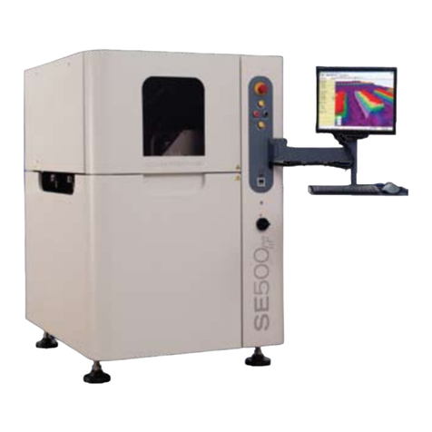
CyberOptics SE505 User manual

SE505
Hardware Manual

Notice
The SE505 is a measuring device intended for use in SMT production environment. Use of this equipment
in a manner not specified in the operating instructions may impair safe operation.
Information in this document is subject to change without notice. CyberOptics Corporation may make
improvements or changes in the products described in this publication at any time.
Trademarks
The following are trademarks or registered trademarks in the United States and other countries:
CyberOptics and SE505 are (owned by CyberOptics Corporation); Windows (owned by Microsoft
Corporation).
Warranty, License, and Terms of Sale
The warranty, software license and other terms and conditions of sale covering CyberOptics products are
set forth in CyberOptics Standard Terms and Conditions of Sale and License available at
www.cyberoptics.com or by calling CyberOptics at 1-800-526-2540 and requesting a copy.
SE505 Hardware Manual
Part Number 8018144, Revision A
April 2011
©2011 CyberOptics Corporation. All Rights Reserved.

CyberOptics Corporation
Table of Contents
Preface vii
Prerequisite Knowledge vii
Documentation vii
Manual Change Request vii
Technical Support ix
1Safety 1
Safety Guidelines 2
General Guidelines 2
Emergency Stop 3
Lockout SE505 4
Safety Interlocks on the Top Cover 5
Indicator Lights 6
Compliance 7
Safety and Conformity Labeling 8
Mechanical Safety Labels 8
Electrical Safety Labels 10
Manufacturing Information Conformance 11
2System Overview 13
SE505 System 14
SE505 Unit 14
SE505 Rear View 16
SE505 Internal Parts 18
Main Electrical Panel 20
Conveyor 22
System Specifications 26
System Requirements 27
Performance Specifications 28
Computer Requirements 28
Dimensions 29
3Installation 31
Unpacking the SE505 System 32
Choosing a Location 33
Installing the System 34
Installing the Light Pole 34
Positioning / Leveling the SE505 System 35
Installing the Sensor 39
Wiring SE505 for Power 41
Turning on System Power 43
Connecting the Air Supply 44

Contents
iv SE505Hardware Manual
Connecting SMEMA Cables 45
Connecting to a Network 46
Connecting to an External Device 47
Wago PLC Assembly 48
Manually Adjusting the Conveyor Width 49
Configuring the Pressure Gauge Display 50
Setting Up System Security 52
Adding Users to the System 53
Assigning Secure Areas 55
Verifying System Accuracy 57
Shutting Down the System 59
Moving the SE505 System 60
Disconnecting Utilities from the System 60
Bypassing the SE505 System 60
4Replacing Components and Preventive Maintenance 63
Maintenance Schedule 64
Main Electrical Panel 65
Replacing Electrical Cables 67
Replacing the AC Main Circuit Breaker 68
Replacing the Fuses 70
Replacing the Air Regulator 72
Replacing Fans 73
Preventive Maintenance 74
Processor Components 77
Replacing Cards 77
Software Upgrades 78
Restoring system disk using Acronis 79
Preventive Maintenance 96
Conveyor Components 98
Replacing the Conveyor Edge Strip Guides 98
Replacing the Conveyor Clamp Blade 101
Replacing the Conveyor Clamp Air Fittings 103
Replacing the Conveyor Clamp Hall Effect Switch 104
Replacing the Conveyor Clamp Cylinder 105
Replacing the Conveyor Motors 107
Replacing the Autowidth Motor 109
Replacing the Conveyor Belts 111
Replacing the Drive Belts 112
Replacing the Idler Pulleys 115
Replacing the Pulley Drive 117
Replacing the Board Sensors 118
Replacing the Panel Lifter Cylinder and Inductive Sensor 120
Preventive Maintenance 122
Gantry Components 132
Replacing the Gantry Forcer 132
Replacing the Gantry Stator 135
CyberOptics Corporation v
Contents
Replacing the X-Axis 138
Replacing the Encoder 141
Preventive Maintenance 142
Adjusting X-Axis Parallelism 149
Adjusting Y-Axis Parallelism 150
Adjusting X-axis and Y-axis Orthogonality 151
Sensor 152
Sensor Replacement 152
Other Components 155
Replacing the Safety Interlock Switch 155
Replacing Leveling Feet 157
5Troubleshooting 159
Safety Circuit Block Diagram 160
AC and DC Distribution Block Diagram 161
SMEMA Connector Pinout 162
System Error Messages 163
Solder Paste Failure Causes 164
SOS 166
Index 167

Contents
vi SE505Hardware Manual

CyberOptics Corporation vii
Preface
Preface
This SE505 Hardware Manual is intended to provide comprehensive information about the
SE505 system.
If you have any questions that are not answered by this guide, contact CyberOptics Customer
Service and Support. Refer to “Technical Support” o n p a g e i x .
Prerequisite Knowledge
●Moderate computer experience
●Moderate Windows®experience
Documentation
Documentation for the SE505 Solder Paste Inspection system consists of the following
information:
●SE505 Hardware Manual
Provides an overview of SE505 components, instructions for how to install and maintain the
SE505 system, parts replacement information, and system specifications.
●SE505 Solder Paste Inspection Software User Guide and Online Help
Provides task-based, step-by-step procedures and descriptions of the software controls for the
Solder Paste Inspection Applications—Engineering Interface.
●SPI Systems Inspection User Guide and Online Help
Provides task-based, step-by-step procedures and descriptions of the software controls for the
Solder Paste Inspection Applications—Operator Interface.
Manual Change Request
Every effort has been made to provide complete and accurate information for operating and
maintaining the SE505 system. If you have suggestions for improvements or find an inaccuracy,
please complete the manual change request form on page viii and forward your suggestions to
CyberOptics.
i
Note: Include a copy of the change request form on the following page and, if applicable, a copy
of the page with the error marked.

viii SE505 Hardware Manual
Manual Change Request
Date:
Zip/Postal Code:
City/State/
Province:
Address:
Company Name:
Originator:
Machine Serial Number Software Version
Manual Revision/Date Page No. or Figure No.
Suggestion:
Fax: +1-763-542-5100
CyberOptics Corp.
Attn: Service
Fax or e-mail to:
Check if page is attached
Country:

CyberOptics Corporation ix
Technical Support
Technical Support
If you have problems operating the SE505, first check the product documentation for more
information.
If you still need assistance, or you discover problems with the documentation, please telephone,
send e-mail, or fax CyberOptics Service and Support.
●Include your serial numbers in all e-mail messages and faxes.
●Have the product serial numbers ready when you telephone CyberOptics.
CyberOptics guarantees a response to all messages during the next CyberOptics business day.
International Technical Support Center
+1-800-526-2540
Fax: +1-763-542-5100
Email: service@cyberoptics.com
Website:www.cyberoptics.com/support
If available in your area, the toll-free number above (+1-800) is answered 24 hours a day, every
day of the week. Where toll-free access is not available, please contact the regional office closest to
you:
North America
CyberOptics Corporation
Minneapolis, Minnesota USA
+1-763-542-5000
Asia-Pacific
CyberOptics Singapore, Ltd.
Singapore
+65-6595-0328
Europe
CyberOptics Ltd.
United Kingdom
+44-(0)-1756-700-330
China
CyberOptics China Company Ltd.
Shanghai
+86-21-6375-6777
Corporate Headquarters
CyberOptics Corporation
Minneapolis, Minnesota USA
+1-763-542-5000
Website: www.cyberoptics.com

xSE505 Hardware Manual

Chapter 1:Safety
2SE505 Hardware Manual
Safety Guidelines
The SE505 system is a measuring device intended for use in SMT production environment.
Use of this equipment in a manner not specified in the operating instructions may impair safe
operation which can cause serious injury.
General Guidelines
●Read and follow instructions provided with all other manufacturer’s documentation.
●Be alert and use common sense when operating any machinery.
●Be sure that you understand the safety considerations and follow the regulations in your
manufacturing facility.
●Do not place liquids or heavy objects on or in the SE505 unit.
●Always wear a static control wristband to prevent damage due to static electricity. The SE505
has an electrostatic discharge plug on the front of the machine by the power buttons to plug
the wristband into.
●Be sure the SE505 is properly grounded through the power connection. To avoid electric
shock, provide an earth ground connection.
●Do not lean on the safety enclosure or the safety enclosure frame.
●Do not remove the safety enclosure or disable the safety interlock mechanisms.
●Do not run the system with panels removed.
●Do not attempt to disassemble or repair any SE505 component without first contacting your
CyberOptics representative.
●Use the SE505 system only indoors.
●To avoid electrical shock, always turn off the power using the AC main circuit breaker before
servicing the unit.
●Only personnel trained by a CyberOptics’ representative are recommended to operate the
SE505 because of the system’s moving parts.
●Parts replacement and maintenance should be performed by trained maintenance personnel,
CyberOptics Representatives and CyberOptics Service and Support.
●System operation should be performed by trained operators.
●During maintenance or repair, all power sources to equipment or machinery shall be
removed and locked or tagged on the de-energized position.
●Locks to assure against inadvertent energizing of the equipment or machinery.
Caution: The system processor contains lithium batteries. There is danger of battery damage if
the battery is incorrectly replaced. Replace only with the same or equivalent type battery
recommended by the manufacturer (CR2032). Dispose of used batteries according to the
manufacturer’s instructions. Recommended that only CyberOptics’ personnels can perform the
replacement of lithium batteries.

CyberOptics Corporation 3
Safety Guidelines
Emergency Stop
Stop all movement on the SE505 system by using the Emergency Stop (E-Stop) button. Motion
will also stop when a safety interlock is disengaged.
Using the Emergency Stop Button (E-Stop)
The E-Stop button is located on the front, right side of the SE505 system. When the E-Stop button
is pushed all motion in the system stops and power is removed from their circuitry.
The E-Stop on this machine is designed to meet the harmonised European standard for safety of
machinery—electrical equipment EN 60204-1 and EN 954-1 Category 4.
Figure 1. Emergency Stop Button
➢To operate the E-Stop
1. Push the red E-Stop button to stop the conveyor and stage movement.
2. Twist and pull the E-Stop button to disengage, then press the yellow E-Stop Reset button to
restart the system.
When the E-Stop button is pressed, or an interlock is broken, the E-Stop button will light up,
giving an indication of the machine status. After clearing the E-Stop button or securing the
interlock, the light turns off.
Caution: Always press the Emergency Stop button before clearing a conveyor malfunction,
before performing machine maintenance, or before reaching inside the machine for any reason.
E-Stop
E-Stop
Reset
i
Note: Air is still supplied to the conveyor panel lifter and the conveyor clamps after pressing the
E-Stop button but they will return to lift down or clamps up when E-Stop button is activated.

Chapter 1:Safety
4SE505 Hardware Manual
Lockout SE505
The lockout label is located at the rear of the SE505 above the AC main circuit breaker. Lockout
of the machine is to prevent unexpected energization or startup of machinery and equipment, or
the release of hazardous energy during service or maintenance activities.
➢To lockout for SE505
1. Turn off all electrical power to the system. For more information, refer to the section
“Shutting Down the System” o n p a g e 5 9 .
2. Check that the air shut-off valve is turned to the horizontal position, which is the OFF
position.
3. Ensure that all energy sources which could activate the machine must be locked out.
4. Insert a padlocking facility into the slot on the AC main circuit breaker (CB1) located at the
rear of the SE505. (See Step 1 in Figure 2)
5. Push the latch of the padlocking facility down. (See Step 2 in Figure 2)
6. Attach a padlock or a tag to the padlocking facility. (See Step 3 in Figure 2)
Figure 2. Lockout Component
Figure 3. Lockout at the rear of SE505
Caution: Turn the AC main circuit breaker to OFF to shut down all electrical power to the
SE505 before starting any replacement operations. For more information, refer to the section
“Shutting Down the System” o n p a g e 5 9 .
1
2
3
Padlocking
Facility Padlock
Padlocking Facility

CyberOptics Corporation 5
Safety Guidelines
Safety Interlocks on the Top Cover
The SE505 is equipped with a safety interlock switch on the top enclosure (hood). The safety
interlock key is located on the top cover. When the safety interlock is engaged, all motion in the
system stops.
When the hood is not securely closed or the switch is defeated in another way (such as putting
the key in the switch) all machine motion is disabled.
➢To reengage the safety interlock switch
1. Remove the key from the switch, if applicable.
2. Close the safety enclosure securely.
3. Press the yellow E-Stop Reset to reengage the system.
Figure 4. Location of safety interlock switch
Caution: It is recommended that the machine should only be run in this way by a trained
technician.
Safety interlock key
Safety interlock switch

Chapter 1:Safety
6SE505 Hardware Manual
Indicator Lights
In both the Teach and Solder Paste Inspection software applications, you can specify the
conditions that turn on the indicator lights on the SE505 light pole. Refer to the Teach Online
Help or Solder Paste Inspection Online Help for these procedures. Refer to Safety of Machinery
EN 60204-1:1998, section 10.3 Indicator lights and displays, Table 3 for standard indicator light
definit ions.
The lights also indicate that the power up sequence for the system is complete. Refer to “Turning
on System Power” o n p a g e 4 3 .

CyberOptics Corporation 7
Compliance
Compliance
This product complies with the requirements of:
●Low Voltage Directive 2006/95/EC
●EMC Directive 89/336/EEC
●Machinery Directive 98/37/EC
Standard Classification Description
EN 61326:1998
Emissions:
Amendments A1, A2
Class A Limits
Electrical Equipment For Measurement,
Control and Laboratory Use EMC
Requirements – Part 1: General Requirements
EN 61326:1998
Immunity:
Amendments A1, A2
Table 1: Limits,
Table 2: Continuous
Monitored Operation
EN 60204-1:2006 Safety Of Machinery—Electrical Equipment Of
Machines – Part 1: General Requirements
EN 954-1:1997 Category 4 Safety Of Machinery—Safety-related Parts Of
Control Systems – General Principles For
Design
ISO 12100-1:2003 Safety Of Machinery—Basic Concepts,
General Principles for Design – Part 1: Basic
Terminology, Methodology
ISO 12100-2:2003 Safety Of Machinery—Basic Concepts,
General Principles for Design – Part 2:
Technical Principles
EN 983:1996 Safety Of Machinery—Safety Requirements
For Fluid Power Systems And Their
Components – Pneumatics

Chapter 1:Safety
8SE505 Hardware Manual
Safety and Conformity Labeling
Mechanical Safety Labels
●Pinch points are clearly labeled on the top front of the frame and on the gantry. The label text
says:
DANGER! Moving gantry can crush and cut. Do not operate with hood interlock defeated.
Figure 5. Pinch Point Danger Label
●Pinch points are also clearly labeled on each side of the machine near the conveyor openings
and on the front of the machine. The label text says:
WARNING! Moving parts can crush and cut. Do not operate with guard removed.
Lockout/tagout before servicing.
Figure 6. Pinch Point Warning Label
●The pressurized device label is located near the air regulator. The maximum air regulator
pressure is 100 psi. The label text says:
CAUTION! Pressurized device. Release air pressure before servicing.
Figure 7. Pressurized Device Label
Located near the conveyor openings Located at the front of the machine
CAUTION
Pressurized
device.
Release air pressure
before servicing.

CyberOptics Corporation 9
Safety and Conformity Labeling
●The read technical manual label is located on the back electronics panel. The label text says:
WARNING! To avoid injury, you MUST read and understand technical manual before
servicing this machine.
Figure 8. Read Manuals Label
●The magnetic warning is located on each stage near the magnetic strips the label text says:
Caution! Strong magnetic field!
Isolate from anyone with a heart pacemaker!
Do not approach with ferrous metals such as iron, steel and nickel!
Credit cards, ATM cards, magnetic data carriers, wristwatches, etc.,
may be damaged when brought too near.
Figure 9. Magnetic Field Caution Label
●The power switch caution label is located on the front of the machine next to the power
switch.
The power switch does not remove all power from the system. Turn off the AC main circuit
breaker at the rear of the machine before servicing the processor.
Figure 10. Power Switch Caution Label
Caution! Strong magnetic field!
Isolate from anyone with a heart pacemaker!
Do not approach with ferrous metals such as iron, steel and nickel!
Credit cards, ATM cards, magnetic data carriers, wristwatches, etc,
may be damaged when brought too near

Chapter 1:Safety
10 SE505 Hardware Manual
Electrical Safety Labels
●The AC input rating label is located on the back electrical panel.
Figure 11. AC Input Rating Label
●A hazardous voltage label is located on the processor power connector on the main electrical
panel. The label text says:
WARNING! LINE VOLTAGE PRESENT WITH MAIN DISCONNECT OFF.
Risk of electric shock or burn.
Turn off main breaker before servicing.
Figure 12. Hazardous Voltage Label
●The ESD earth ground label is located near the ESD grounding plug on the outside of the
system.
Figure 13. ESD Earth Ground Label
●The protective earth ground label is located near the PE terminal on the inside of the system
at the back electrical panel and gantry grounding plate.
Figure 14. Protective Earth Ground Label
●The lockout label is located at the rear of the machine above the AC main circuit breaker.
Figure 15. Lockout Label
LINE VOLTAGE PRESENT WITH
MAIN DISCONNECT OFF.
Risk of electric shock or burn.
Turn off main breaker before
servicing.
WARNING
Table of contents
Other CyberOptics Measuring Instrument manuals

CyberOptics
CyberOptics SE500CP User manual

CyberOptics
CyberOptics Auto Gapping System AGS User manual

CyberOptics
CyberOptics SE 300 Ultra Application guide

CyberOptics
CyberOptics Auto Teaching System ATS User manual

CyberOptics
CyberOptics Auto Vibration System AVS User manual

CyberOptics
CyberOptics Auto Leveling System ALS User manual
Popular Measuring Instrument manuals by other brands

SevenStar
SevenStar CS100A MFC user manual

YOKOGAWA
YOKOGAWA AQ6151B Getting started guide

Extech Instruments
Extech Instruments 407735 user guide

horiba
horiba LaquaTwin B-771 instruction manual

LEGRAND
LEGRAND LG-41492 quick start guide

Pilot Communications
Pilot Communications PMAC615 Installation & operation manual