CyberPower Network Management Card User manual

User’s Manual
CyberPower Network
Management Card
I
ntelligent Network Management
Card allows UPS to be managed,
monitored, and configured via
Internet Browser
K01-SNMP0001

TABLE OF CONTENTS
INTRODUCTION…………………………………...………………… 1
INSTALLATION GUIDE…………………………………...………… 3
CONFIGURATION GUIDE….……………………………….....…… 4
Monitoring…………………………………………………………. 4
Current Status………………………………………………….. 4
UPS Information……….………..……………………………. 5
Control……………………………………………………………… 5
UPS Control…………………………….………………….…… 5
UPS Reboot……………………….…………………………….. 6
UPS Schedule………………………….……………………….. 7
System…………………………….……………………………….. 8
User Account……………………………….………………….. 8
System Setting…………………………….…………………… 8
Identification…………………………..……………………….. 8
Network…………………………….…….………………………… 9
TCP/IP……………………………………..…………………….. 9
Access Control…………………..…………………………….. 9
Trap Notification…………………..…………………………… 9
Events…………………..…………………..……………………… 10
Event Log…………………………………..………………….. 10
Event Action…………………………………………………… 10
Appendix 1. IP Address Settings of CyberPower Network Management
Card……………………………………………………………...
11

CyberPower Network Management System
1
INTRODUCTION
Overview
CyberPower Network Management Card is an external card that allows remote monitoring and
control of a UPS via the internet. After installing the hardware and setting up an IP address, the
user can access, monitor and control the UPS from anywhere in the world! No software
installation is needed. Simply use a web browser such as Internet Explorer or Netscape to
access your UPS. Servers/workstations protected by UPS could be installed with PowerPanel
Shutdown Service to enjoy extra value-packaged features.
Features
zRemote management and configuration of UPS via Web Browser or NMS
zSupports TCP/IP, UDP, SNMP, HTTP protocol
zAutomatic events notification via SNMP Trap
zFlexible Event Action setting
zAuto-shutdown to protect servers/workstations from data loss due to power failure.
zSchedule shutdown/startup/reboot of UPS remotely
zEvent logging to trace UPS operation history
zSNMP MIB provided
z10Mbps fast Ethernet compatible
zQuick installation and user friendly interface
zSecurity management provided.
System Requirements
A computer with a Windows Operating System
An Ethernet cable connection to an existing network
NMS (Network Management Station) compliant with SNMP
Application:
Unpacking
Inspect the Net Agent upon receipt. The package should contain the following:
CyberPower Network Management Card
RS232 cable to connect to the CyberPower Network Management Card with UPS;
User’s Manual;

CyberPowe
Definitions for LED Indicators
r Network Management System
2
Description
1) Serial Port provides connection and communication between the UPS and Network
Management Card
2) Reset Button is used to reset the settings. When the Reset Button is pushed for 3 seconds,
all settings except for the IP address for Network Management Card will refresh to default
values. When the Reset Button is pushed for more than 3 seconds, all settings including the
IP address for CyberPower Network Management Card will reset to default value.
3) DC power input allows input of power by plugging the provided AC adapter into wall socket.
The DC power input is only used when the Network Management card is connected to few
selected UPS models that don’t supply power to the Network Management Card.
4) MSG Indicator indicates the status of connection between UPS and Network Management
Card. This indicator light will flash when Network Management Card IS NOT connected to the
UPS.
5) PWR Indicator indicates the status of on/off. It illuminates when Network Management Card
is powered ON.
6) LINK Indicator indicates the status of connecting to the network. It illuminates when Network
Management Card is connected to the network.
7) 10M Ethernet connector
Indicator Mode Condition
Off The Network Management Card is connected to UPS
MSG
(Red) Flashing No connection between the Network Management Card and
the UPS
Off The Network Management Card Power OffPWR
(Green) On The Network Management Card Power On
Off The Network Management Card is connected to NetworkLINK
(Yellow) On The Network Management Card is disconnected to Network

CyberPower Network Management System
INSTALLATION GUIDE
Step 1. Hardware Installation
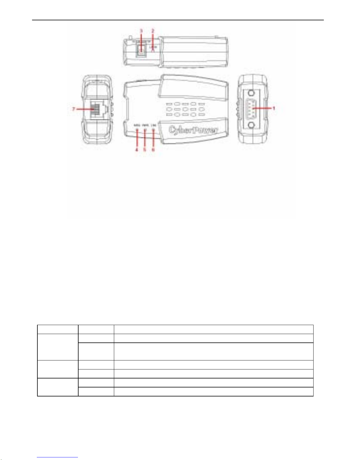
1. Connect the Ethernet cable to the LAN port of the CyberPower Network Management Card.
2. Connect the CyberPower Network Management Card to the UPS communication port. It
is optional to use the serial cable included.
3. Connect the supplied DC adapter to the Network Management Card Adapter and plug into
the wall socket. (For some selected UPS models only).
4. After the above procedures are done, press the Reset Button of the Network Management
Card continuously for 7 seconds to ensure the IP Address to remain default value.
5. Disconnect the Network Management Card from the UPS communication port and then
re-connect it to the UPS communication port.
Step 2. Setup the IP address for the CyberPower Network Management Card.
1. Get the MAC address indicated on the label of the Network Management Card rear panel.
(Each Management Card has a unique MAC address).
2. For example 1, to assign an IP address 192.168.20.240 in the same subnet as your
computer for Network Management Card, which has the MAC address 00-0c-15-00-00-01:
Run an ARP command in MS-DOS mode and type:
arp –s 192.168.20.240 00-0c-15-00-00-01
and press Enter to set the IP address.
3. To verify the setting, please type:
ping 192.168.20.240
and press Enter to get replies. If replies are received, the IP address has been set.
To find an IP address for the Network Management Card, please refer to Appendix 2.
If you want to assign an IP address which is in different subnet to your computer for Network
Management Card, you should followed Step 2, and then enter the Browser Mode
Configuration to establish the IP address.
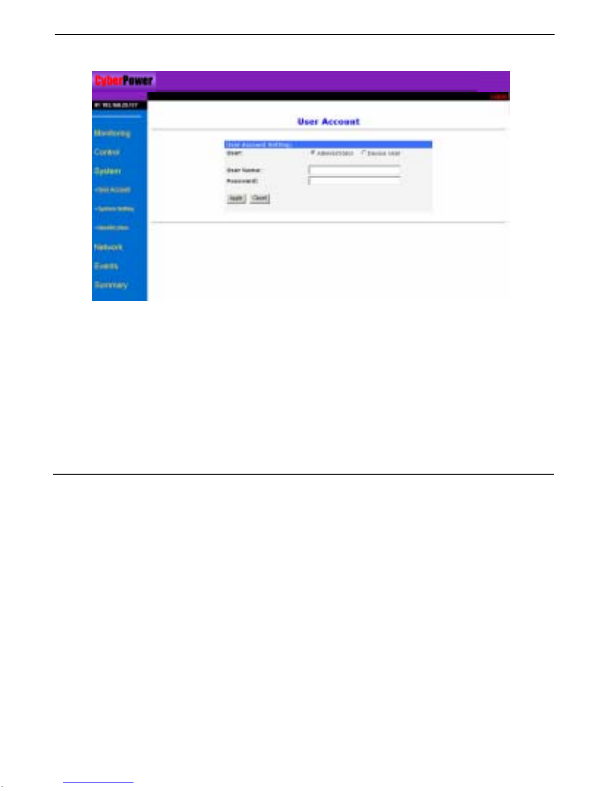
1. Open your Web Browser (Internet Explorer or Netscape)
2. Enter the IP Address which is in the same subnet as your computer.
3. On the login page, enter the current password. Put the default username “cyber” and
password “cyber”.
4. Click on TCP/IP Configuration, selected from Network menu, to change the IP address.
Click Apply to have it become effective.
3

CyberPower Network Management System
4
CONFIGURATION GUIDE
[Monitoring] menu contains [Current Status] page and [UPS Information] page
[Current Status] displays basic information of UPS current status.
Status Field Definition
Input Line Voltage Shows the current input voltage of the utility power
Output Frequency Displays the frequency of the utility power
Maximum Line Voltage Identifies the highest voltage of the utility power input to
the UPS during the previous minute of operation.
Minimum Line Voltage Identifies the lowest voltage of the utility power input to
the UPS during the previous minute of operation.
Output Voltage Shows the output voltage of the UPS.
UPS Load Shows the % of battery capacity that is currently being
used.
Internal Temperature Displays the internal operating temperature of the UPS.
Battery Capacity Displays the current battery charge level.
On Battery Time Displays the battery time available. This display factors
in the UPS load and the Battery Capacity.

CyberPower Network Management System
5
[UPS Information] provides the technical specifications of your UPS.
Information Description
Model Name Displays the UPS’s model number
Voltage Rating Identifies the current AC voltage to the UPS.
Working Frequency Displays the current frequency of the UPS.
Power Rating Displays the capacity of the UPS in VA.
Load Power Identifies the capacity of the UPS in Watts.
Current Rating Identifies the Current Rating of the UPS supplied by the
input voltage
Battery Voltage Rating Displays the DC voltage of the battery.
Firmware Version Shows the firmware version of the UPS.
Self-test Date Displays the date of last self-tests
Self-test Result Displays the latest self-test result.
Please Note: [Self-test Date] and [Self-test Result] will only display when a self-test has been
set or performed.
[Control] menu contains [UPS Control] page, [UPS Reboot] page, and [UPS Schedule] page.
[UPS Control] allows basic remote control of the UPS.
Select one command by clicking its button for a test and then click [Apply] for operation. A
selected button will turn a green color. Only by clicking [Apply] will the selected command
become active. Select [Cancel] to stop any command that has been selected.

CyberPower Network Management System
6
Please Note: If the UPS is shut OFF, the following commands will not work. CyberPower
Network Management Card will display the message: “Command fails. UPS is turned off.”
Commands Definition
Auto Diagnostics The Deep Battery test will discharge the batteries. The
test will automatically stop when the batteries are low,
and return to AC-On line power.
Deep Battery Test This command will stop the Deep Battery Test.
Cancel Deep Battery Test To turn off the UPS (no power output from the outlets).
Put UPS to Sleep Mode To turn on the UPS when it is in sleep mode.
Wake up UPS To turn the audible alarm of the UPS on/off.
Turn Off UPS Buzzer To turn the UPS buzzer
[UPS Reboot] allows advanced remote control of the UPS. Select one command by clicking its
button for a test and then click [Apply] for operation. A selected button will turn a green color.
Only by clicking [Apply] will the selected command become active. Select [Cancel] to refresh the
selection.
Note: The commands in [UPS Reboot] menu may change by the settings in the [UPS Schedule]
menu.
Commands Definition
Reboot UPS Immediately To turn the UPS off and then on again.
Delay 03 min(s) to Reboot
UPS
3 minutes is a default value. The user may select any
number between 1-99. The UPS will shut off and wait
the set amount of time before turning back on.
Cancel Reboot UPS To stop the previous command “Delay 03 min(s) to
Reboot UPS.
Turn Off UPS Immediately To turn the UPS off immediately.
Delay 03 min(s) to Turn Off
UPS
3 minutes is a default value. The user may select any
number between 1-99. The UPS will wait the set
amount of time before turning OFF.
Cancel Turn Off UPS To stop the previous command “Delay 03 min(s) to
Turn Off UPS
Turn On UPS Immediately To turn on UPS when it is turned off.

CyberPower Network Management System
7
[UPS Schedule]: The user may set the UPS to automatically shutdown and restart at consistent
times - weekly or daily.
[Special Shutdown]: The user may set a specific date and time for UPS shutdown.
[Weekly]: Set a specific day and time of the week for UPS shutdown.
[Daily]: Set a specific time of the day for UPS shutdown.
1. Click [Special], [Daily] or [Weekly] scheduled shutdown features to enter each setup menu.
2. Enter the date and time to shut down the UPS. Please note that time is entered using
24Hr clock format (hh:mm).
3. Select either [Never], [Immediately], [Same Day] or [Next Day] for the UPS recover power.
4. Click [Add] to add the item to the Schedule. Click [Cancel] to remove the item from the
Schedule.
5. Applied settings are listed in [Schedule Log] menu.
Please Note: The management system allows only 10 inputs of scheduled settings.

CyberPower Network Management System
8
[System] menu contains [User Account] page, [System Setting] page and [System Identification]
page.
[User Account] serves to setup user accounts. The system allows one administrator and two
device users to access the system. An administrator can access all of the management menus.A
device user can only access [Monitoring], [Events], and [Summary]. Only one user at a time
can enter into the web browser.
1. Select [Administrator] / [Device User] and enter the User Name and Password.
2. Click [Apply].
3. Type the password to confirm the password was keyed properly.
[System Setting] serves to setup the CyberPower Network Management Card’s Date, Time and
Temperature Display.
1. Insert the date and time and choose either Celsius or Fahrenheit for the temperature
display.
2. Click [Apply] to activate the settings.
[Identification] servers to assign the system’s name, contact, and location of the system.

CyberPower Network Management System
9
[Network] menu contains [TCP/IP] page, [Access Control] page and [Trap Notification] page.
[TCP/IP] displays IP Address, Subnet Mask, Default Gateway and System MAC Address.
Click [Apply] to activate the settings, click [Cancel] to revert to previous inputs.
[Access Control] serves to control access to the NMS. Limit system data access through
SNMP.
1. Input the manager IP address. This address will limit the access to the NMS. The default
value 0.0.0.0 or 255.255.255.255 allows access for all NMS.
2. Input the community (functioned as password, maximum of 15 characters).
3. Select one of the permission options: [Read], [Write], or [Disable].
4. Click [Apply] to activate the settings, click [Cancel] to revert to previous inputs.
Definitions for Permission levels:
Read The NMS can read data at any time, but can never write data.
Write The NMS can read and write data at any time (provided there is not
another user logged in).
Disabled The NMS cannot use ‘Read’ or ‘Write’.
[Trap Notification]: Identify NMS that will receive traps.
1. Input the receivers IP address. This address will identify the receiver of traps. The default
value 0.0.0.0 or 255.255.255.255 defines all NMS as receivers.
2. Input the community (functioned as password, maximum of 15 characters).
3. Select one option [Enable] or [Disable].
4. Click [Apply] to activate the settings, click [Cancel] to revert to the previous settings.
Enable The trap will be generated.
Disable The trap will not be generated.

CyberPower Network Management System
10
[Event] displays an event log for the UPS. The section contains [Event Log] and [Action
Configuration].
[Event Log] displays CyberPower Network Management Card events by date and time. More
than 200 events can be displayed.
[Event Action]: There are three severity levels, Information, Warning, and Severe. Please
refer to their definitions below. The User can assign which severity levels will be recorded in the
event log and which severity levels will cause SNMP traps to be sent.
Information indicates an event that requires no action.
Warning indicates an event that does not require immediate attention, but this condition should
be monitored.
Severe indicates an event that requires immediate attention.
1. Determine the severity levels and click the option buttons.
2. Click [Apply] to activate the settings.
[Summary]: Displays the current UPS and CyberPower Network Management Card Status.

CyberPower Network Management System
11
Appendix 1 IP Address Settings of CyberPower Network Management Card
Overview
All devices on a computer network need to have an IP address. Each device’s IP address is
exclusive. The same address cannot be used twice. In order to assign an IP address to the
CyberPower Network Management Card, first, you must determine the range of the IP address,
and then you actually decide a number that is in this range. The most important is to find an IP
address that is not currently used.
PLEASE NOTE: You may need to contact your network administrator. He/She will assign the IP
addresses for your Management Card.
Procedures to find an IP address:
1. Locate the subnet of CyberPower Network Management Card.
One way to determine the range of possible IP addresses is to access the computer. Click
on [Start] and select [Run]. Type “command” into the open box and click [OK]. At the DOS
Mode Prompt type “ipconfig /all” and press [Enter]. The computer will display network
information as below:
Ethernet adapter
Connection-specific DNS Suffix…………: xxxx.com
Description……………………: D-Link DE220 ISA PnP LAN adapter
Physical Address…………….: 00-80-C8-DA-7A-C0
DHCP Enabled……………....: Yes
Autoconfiguration Enabled ...: Yes
IPAddress…………………..: 192.168.20.102
Subnet Mask………………..: 255.255.255.0
Default Gateway……..……...: 192.168.20.1
DHCP Server…………..…….: 192.168.20.1
DNS Servers…………………: 211.20.71.202
168.95.1.1
2. Select an IP Address for CyberPower Network Management Card
Make sure the IP Addresses for the computer and the Network Management Card belong to
the same subnet. Refer to the above network information, the possible IP Address for
Network Management Card could be 192.168.20.* (* hereafter represents any number
between 1 and 255). Similarly, if the Subnet Mask is 255.255.0.0, the IP Address for
Network Management Card could be set up as 192.168.*.* to reach the same subnet with
the computer.
To ensure there is no other equipment connected to the network using the same IP Address,
you could place a command “Ping 192.168.20.240” in MS-DOS mode when the IP Address
you would like to set is 192.168.20.240. If the response is presented as below, the IP
address is not used yet and available for CyberPower Network Management Card.
Pinging 192.168.20.240 with 32 bytes of data:
Request timed out.
Request timed out.
Request timed out.
Request timed out.

CyberPower Network Management System
12
If the response is shown as below, the IP address has been used already by another
equipment. Try another IP address until an available address is found.
Pinging 192.168.20.240 with 32 bytes of data:
Reply from 192.168.20.240: bytes=32 time<10ms TTL=64
Other manuals for Network Management Card
1
Table of contents
Other CyberPower Network Card manuals