6 61222003L1-5, Issue 1 61222003L1-5A
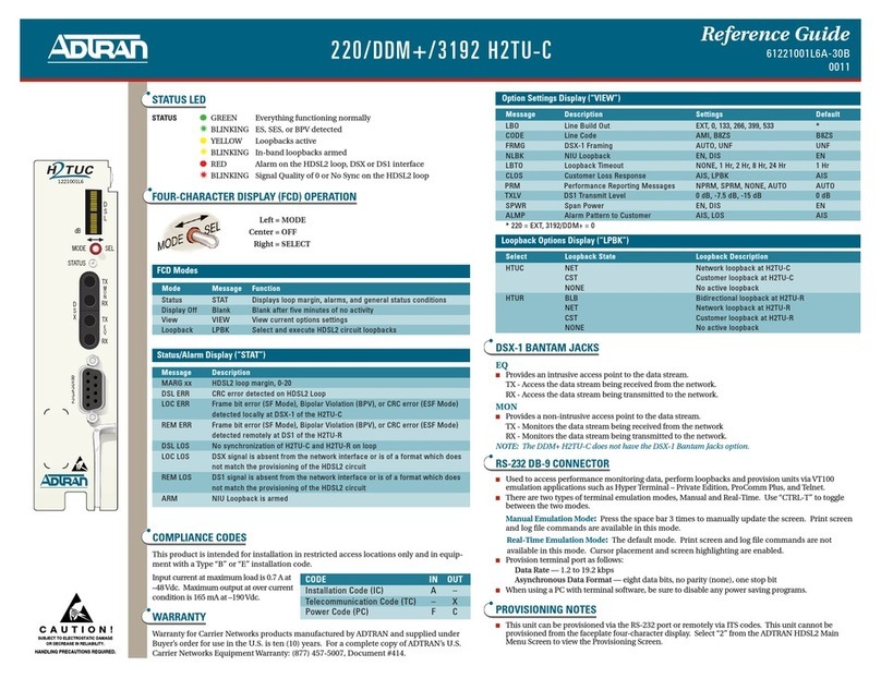
The configuration parameters available in the
Provisioning Mode are described in Table 4.
View Mode
Select the VIEW mode to scroll through each option
setting ithout changing any of the parameters. (This
information is useful in verifying the current settings
of the HDSL2 circuit.) A listing of the circuit
parameters appears in Table 4. Each option ill flash
follo ed by the current setting. The display ill
return to “VIEW” mode after scrolling through each
of the options. To exit “VIEW” mode, press the
MODE button for three seconds. If connected to
H2TU-Rs ith hard are s itches the “VIEW” mode
ill also display these settings.
Default Mode
The DFLT mode can be used to enable all of the
factory-default HDSL2 circuit configuration
parameters. Once in this mode, you ill be prompted
to select the factory defaults or not by entering “YES”
or “NO,” respectively. Use the MODE button to
toggle bet een “YES” and “NO,” if necessary. If the
SELECT button is pressed hile the display reads
“YES,” then the factory defaults ill be enabled and
the message “DONE” ill appear. If the SELECT
button is pressed hile the display reads “NO,” then
the unit ill retain the current settings.
Loopback Mode
This mode selects and executes HDSL2 circuit
loopbacks. Only one loopback may be active at a
time. From the top level of the display, press the
“MODE” to scroll to “LPBK.” Press the “SELECT”
button to force the display into the loopback branch.
Use the MODE button to scroll through the different
HDSL2 system units on the circuit, hich may
include H2TU-C and H2TU-R. The display ill
toggle bet een the unit name and the current loopback
state of that unit. The choices are NONE, NET
(loopback to ard the net ork) and CST (loopback
to ard the customer).
To change the loopback state of a particular unit, first
press the “SELECT” button hen the appropriate
HDSL2 system unit appears. The unit’s current
loopback state ill be displayed. Use the “MODE”
button to scroll through the available choices. Once
the desired choice appears, use the “SELECT” button
to activate the choice. Press and hold the “MODE”
button for three seconds to return to the top level of
the display. Available loopbacks are described in
Table 5.
1 The forced frame format conversion (FFFC) mode sets the H2TU-C to ESF and the H2TU-R to SF. This mode should be used to force SF (DS1
from customer) to ESF (DSX-1 to net ork) conversion in the absence of net ork-provided ESF framing.
2 When operating in FT1 mode and during periods of T1 loss of signal, LOS, or T1 AIS from the customer CI, the HDSL2 system ill send in the
net ork direction from the H2TU-C a Fractional DS1 idle signal consisting of a repeating 7E (HEX) byte payload ithin a framed/unframed T1
signal. In addition, hen optioned for FT1 mode, the setting for Customer Loss Response is ignored.
* These are not changeable from the Four Character Display.
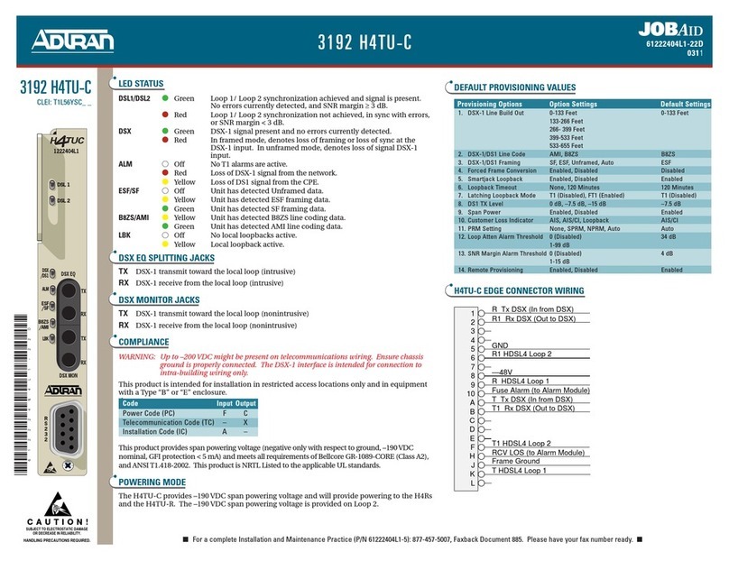
Table 4. Option Setting Parameters
Faceplate
Display Message Description Settings Default
LBO .................................. Line Build Out ............................................. 0, 133, 266, 399, 533 ................................... 0
CODE ............................... Line Code ..................................................... AMI, B8ZS ................................................... B8ZS
FRMG ............................... DSX-1 Framing ............................................ AUTO, ESF, SF, UNF, FFFC 1................... AUTO
NLBK ............................... NIU Loopback .............................................. EN, DIS ........................................................ EN
NELB ................................ Ne England 1:6 Loopback ........................ EN, DIS ........................................................ DIS
LBTO ................................ Loopback Time Out ..................................... NONE, 20, 60, 120 ...................................... 120
CLOS ................................ Customer Loss Response ............................. AISC, AIS, LPBK ........................................ AISC
LTCH ................................ Latching Loopback ...................................... T1, FT1 2....................................................... T1
PRM .................................. Performance Reporting Message ................. NONE, SPRM, NPRM ................................ NONE
TXLV ............................... DS1 Transmit Level ..................................... 0 dB, -7.5 dB, -15 dB ................................... -7.5 dB
SALM ............................... Shelf Alarm .................................................. EN, DIS ........................................................ EN
SPWR ............................... Span Po er ................................................... EN, DIS ........................................................ EN
* ........................................ Loop Attenuation Alarm Threshold ............ 0 (Disabled), 1-99 ........................................ 40 dB
* ........................................ SNR Margin Alarm Threshold .................... 0 (Disabled), 1-15 ........................................ 04 dB
