CycleOps 100 PRO User manual

1
IndoorCycleAssemblyServiceManual
ProSeries:
400Pro
300Pro
200Pro
100Pro
CHAPTERS:
1.UNPACKINGTHECYCLEOPSINDOORCYCLE.......1
2.BIKEASSEMBLY.............................................................1
AttachStabilizerFeet
AttachHandlebars
SeatAssembly
AttachPedals
AttachConsoleBracketandConsole
LevelingtheBike
3.GENERALUSE...............................................................5
4.COMMONADJUSTMENTS........................................5
FlywheelAdjustment
ReplacingHubBatteries
BrakeAdjustment
ReplacingBrakePads
ReplacingResistanceKnob
5.LUBRICATION................................................................9
6.ELECTRONICS...............................................................11
7.RFINTERFERENCE/GROUPUSECASE.....................
8.WARRANTY.....................................................................11

1
CHAPTER1:UnPACkingTHECyClEOPsindOORCyClE
Placetheboxuprightandcuttheplasticbindingstraps. LiftthetopoftheboxtoexposetheIndoorCycleandpackaging. Re-
moveallpartsfromtheboxandfoaminsertsandensureallthefollowingpartsareincluded:
Part Qty
Stabilizerfront 1
Stabilizerrear 1
Mainbikeassembly 1
Handlebartube 1
Seatposttube 1
Saddlew/clamp 1
Seatassembly 1
Handlebar 1
Waterbottleholder 1
Pedalset 1
IPhardwarekit 1
Stabilizerbolts 8
Stabilizerboltwashers 8
ConsoleBracketbolts 2
Waterbottlespacer 1
4mmSpacerbolts 2
Multi-purposewrench 1
5mmallenwrench 1
4mmallenwrench 1
ConsoleBracketw/screw 1
Console(400Pro,300Pro,200Pro) 1
CHAPTER2:BikEAssEmBly
Step1:AttachStabilizerFeet
1.Notethedifferencebetweenthefrontandrearstabilizerfeet. ThelargerfootwithwheelsgoesintherearoftheIC.
2.Aligntherearbaseoftheframewiththerearstabilizerandsecureitwithfour6mmboltswithwashers. NOTE:Tighten
theinnerboltsfirst,andthenproceedtotheouterboltstoensurethefootissecuredproperlyandevenly.
3.Repeatwiththefrontstabilizer.
FrontStabilizerFeet
RearStabilizerFeet

2
Step2:AttachHandlebars
Step3:SeatAssembly
A.LoosentheL-handleonseatclampassemblyontheseattube.
B.Attachthesaddletotheseatpostclamp,usinga6mmAllenwrench.
Makesurebothrailsofthesaddleareproperlyseatedintheclamp
andtightenthe6mmAllenbolt. Ifdesired,anystandardbicyclesaddle
canbeattachedtotheCycleOpsIndoorCycle. Ensurethesaddleis
levelandparalleltothefloorforoptimumcomfort. Theseatmayneed
tigheningafterfirstfewuses.
C.OncetheSaddleislevelandproperlytightenedintheclamp,attach
theplasticendcapwithtwooftheincludedscrews.
D.Insomeinstances,ashorterseatpostisrequiredforindividuals
underfivefeettall.Youcanreplacethestandardseatclampmecha-
nismwithpart#16616.ContactSarisCyclingGrouptoorderthispart.
Followtheinstructionsprovidedwiththatpartforinstallation.
A
B
C
InserttheHandlebarpostintothehead
tubeandsecureitusingtheL-handle.
SlidetheplasticshimontotheD-shaped
tubeonthewaterbottleholder.
Slidethewaterbottleholderandplastic
spacerontothehandlebarassembly.
Securethewaterbottleholderandspacer
tohandlebarassemblyusing2-4mm
allenbolts
Carefullyslidethehandlebarontothe
handlebarpost. Oncethehandlebarisinplace,
secureitwiththeL-shaped
tensionhandle.

3
Placebracketontothehandlebarsas
shown.
Insertscrewsthroughconsolebracket,
handlebarbracket,andtightentogether.
Slidetheconsoledowncompletelydown
ontothebracket.Toensureasolidcon-
nectionbetweentheconsoleandthe
bracketmakesurethecontactpoints
betweentheconsoleandbracketremain
cleanandfreefrommoistureordebris.
Step4:AttachPedals
TheCycleOpsICincludesastandardpedalset;however,tomimicthefitandfeelofyour
ownbikeyoumayalsoattachyourownpedalsperthemanufacturers’specifications.
Notethatpedalsaredesignedtobeinstalledspecificallyontherightorleft-hand
sideoftheIC. Improperinstallationcanresultindamagetothecrank. Damage
causedbyimpropercrankinstallationisnotcoveredunderwarranty.
Attachyourpedalsontothebikewithapedalwrench. Typically,each
pedalismarkedwithan“R”oran“L”ontheveryendofthespindlepastthethreads.
Thismarkindicateswhichsideofthebikethepedalisintendedtomounton.
Thisisimportantsincethethreaddirectionsaredifferentforeachpedal.
A.Locatethepedalthathasthe“R”onthespindle. Thispedalisfortherightsidecrank
armofthebike(chainguardside)andisrighthandthreaded
(turnclockwisetotighten).
B.Locatethepedalthathasthe“L”onthespindle.Turnthespindleleft(counter-clock-
wise)totightenasthe“L”spindleisreversethreaded.
Step5:AttachConsoleBracketandConsole(Ifapplicable)
Bracket
WhenfirstsettinguptheCycleOpsICyoumustattachtheconsolebrackettothebike.To
dothis,followtheinstructionsbelow:
B
B
A

4
IMPORTANT!HowToZeroTorque
Thetorquemustbezeroedtoensurethattheconsoledisplaysthemostaccuratepowerinformation.Ifthe
instantaneouspowerispositiveornegative,thetorqueneedstobezeroed.Theseoperationsmustbedone
withNOtensiononthechainandwithNOforcebeingplacedonthepedals.Also,thetransmissioniconmust
beilluminated.
Tozerotorque,firstensurethetransmissioniconisshowing.Thenpress[DOWNARROW]tomovethecursor
to[WATTS].Press[SELECT]tochangeto[INCH-LBS].Thenholddown[SELECT]againuntil“0”isshown(about
10seconds).Press[SELECT]toreturnto[WATTS].Thetorquevaluewillnowreadzero.
Ifthetorquedoesnotzeroonthefirstattemptafter~10seconds,repeattheprocedure.
Youcansecurethefeetbytighteningthe
levelerlocks.
LevelerLock
Levelingthebike
Oncetheaboveassemblyinstructionshavebeenfollowed,movethebiketowhereitwillbeusedandlevelitproperly.To levelthe
bike,adjustthelevelingfeetunderneaththestabilizersuntilthereisnorockingormovementofthebike. Itisimportanttolevel
thebikeforlongtermcare.
Batteries:Theconsoleshipswithbatteries.Intheeventthebatteriesneedtobereplacedovertime,followthesesimplesteps:
RemovethebackcoverwithasmallPhillips-headscrewdriver.
Removebatteries.
ReplacewithfreshAAAbatteries,payingattentiontoproperlylineupthe+/-poles.
ReplacebatterydoorandsecurewithsmallPhillips-headscrewdriver.

5
CHAPTER3:gEnERAlUsE
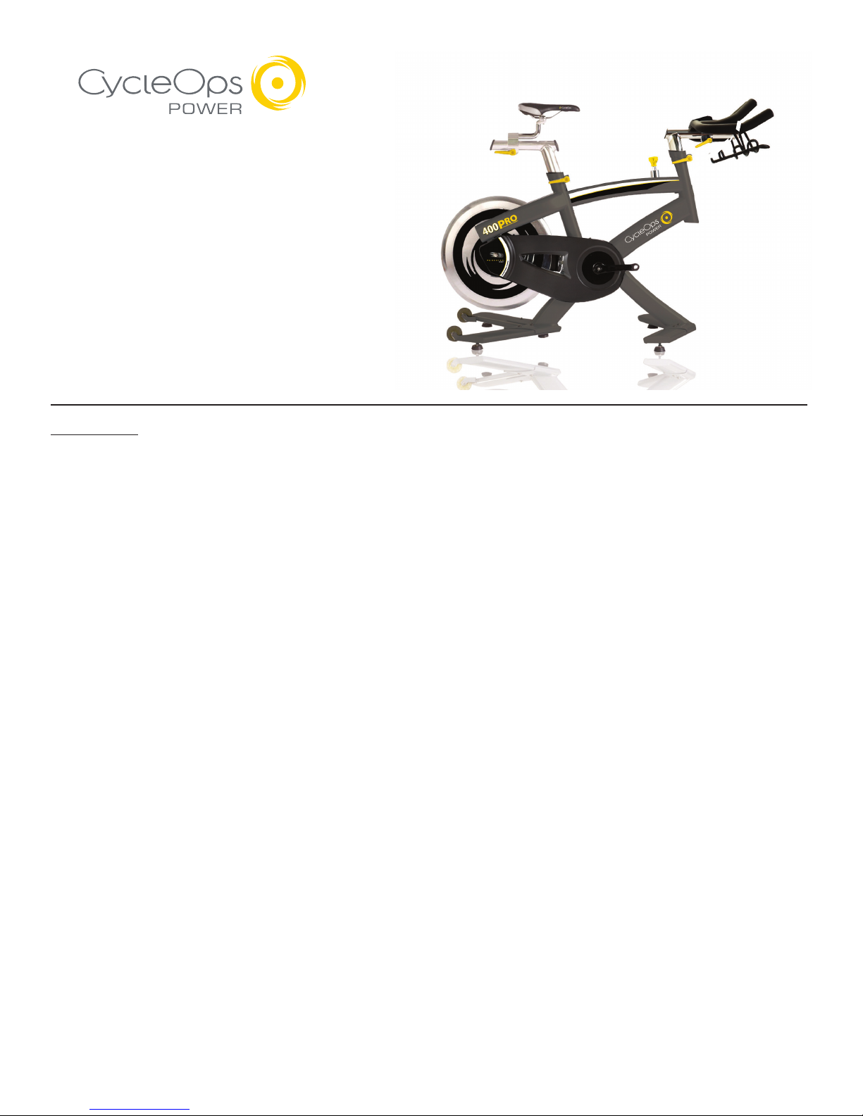
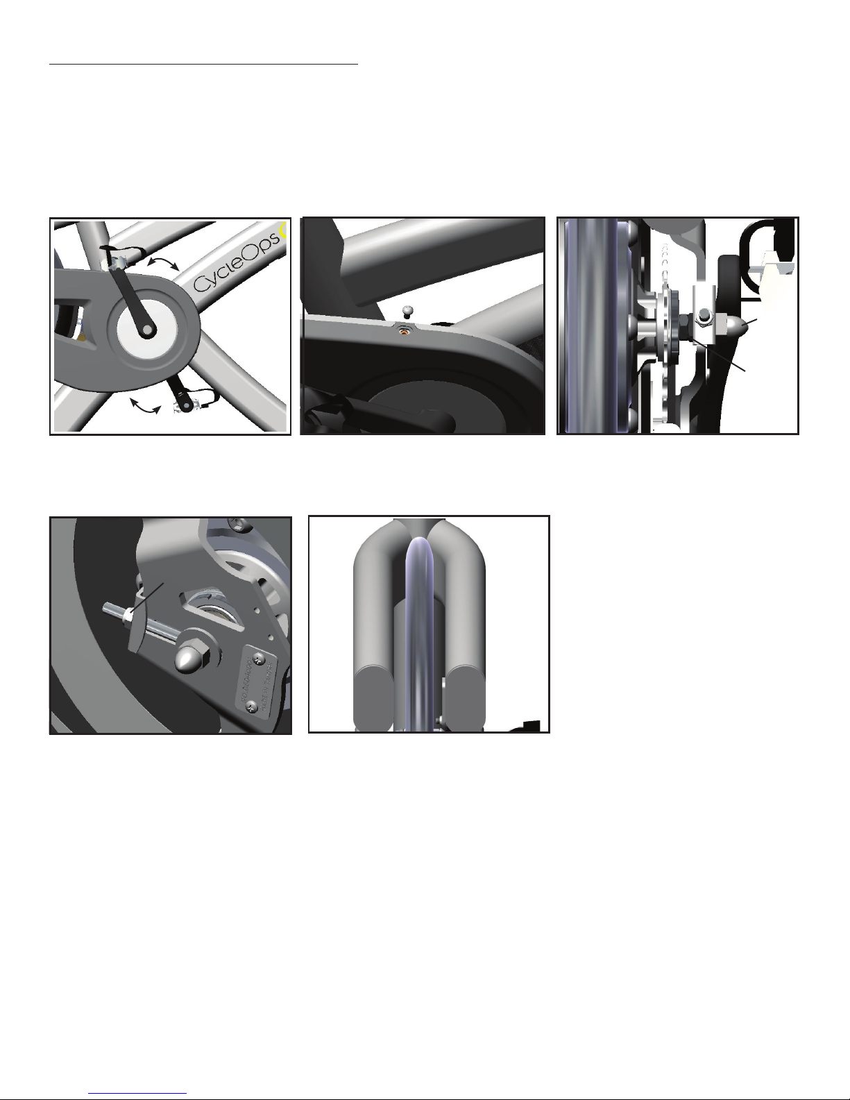
TheCycleOpsIndoorCycleiseasytouse.Simplysitonthecycle,tightenthepedal
strapsandbegincycling.TheCycleOpsindoorcycleallowstheuserfullcontrolover
resistancebysimplyadjustingtheresistanceknob.Typically,lowerresistancelevels
enableyoutopedalatafasterpace,placingincreaseddemandonthecardiovascu-
larsystem.Higherresistancelevelswilltypicallydeliveragreatermuscle/endurance
workoutatlowerRPMs.RPMparametersintheprogramrangefrom60-110RPM.
Additionally,theindoorcycleoffersseatandhandlebaradjustments,allowingthe
CycleOpsindoorcycletobeconfiguredtoeachuser’scomfortzone.
Thissectionprovidestheinstructionsformakingseatadjustments,
handlebaradjustments,pedalstrapadjustments,andforcontrollingresistance.
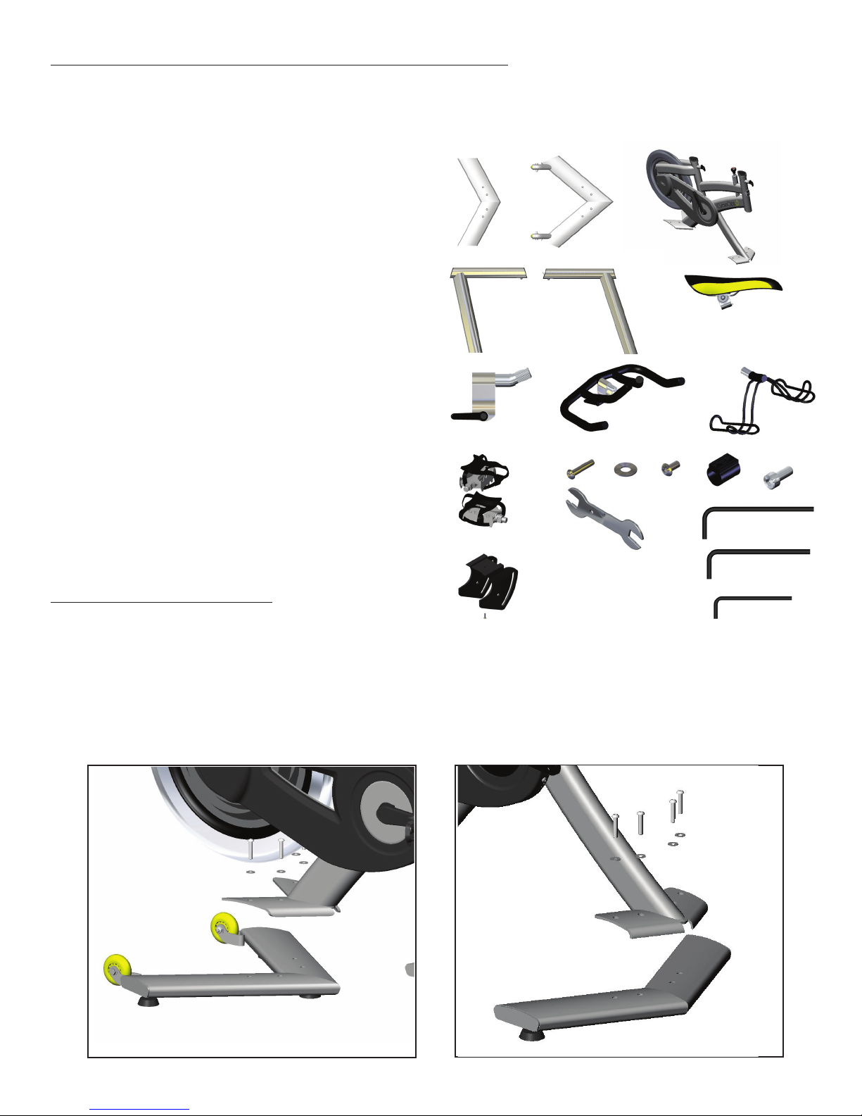
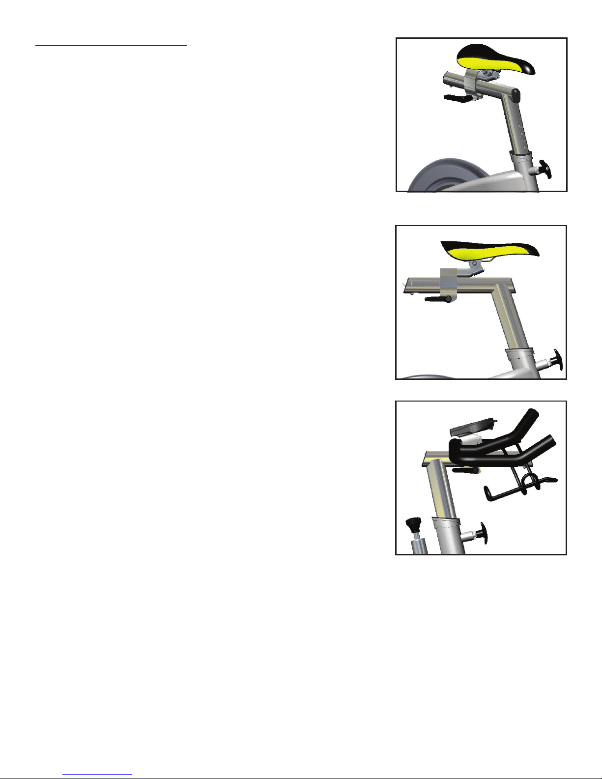
SeatAdjustments
Properseatheighthelpsensuremaximumexerciseefficiencyandcomfort,while
reducingtheriskofinjury.Adjusttheseatheightsothatthekneejointisslightly
flexedwhentheextendedlegisatthebottomofthepedalstroke.Oncetheproper
heighthasbeenachieved,adjusttheseatforwardorbacksothatwhenthefeetare
inthe3o’clockand9o’clockpositions,thekneesaredirectlyoverthepedalspindle.
Toadjusttheseatheight:
Dismountthecycle.Turntheseatheightpop-pincounterclockwiseandpullouton
thepintoreleaseitfromitscurrentpresetlocation.Raiseorlowertheseattothe
desiredheight,thengentlyreleasethepop-pin.Raiseorlowertheseatslightly,ifnec-
essary,untilthepop-pinengagesapresethole.Turnthepop-pinclockwisetosecure.
Toadjusttheseathorizontalposition:
Dismounttheindoorcycle.Loosentheseatfore-and-afttensionhandlebyturning
thehandlecounterclockwise.Movetheseatforwardorbacktothedesiredposition,
thentightenthetensionhandlebyturningclockwise.Besuretotightenthehandle
firmly.
HandlebarAdjustments
Properpositionforthehandlebarisbasedprimarilyoncomfort.Typically,thehandle-
barshouldbepositionedevenwithorslightlyhigherthantheseat.
Dismounttheindoorcycle TurnL-handlecounterclockwisetoreleaseitfromitscur-
rentpresetlocation.Raiseorlowerthehandlebartothedesiredheight,thentighten
L-handle.TurntheL-handleclockwisetosecure.
Toadjustthehandlebarhorizontalposition:
Dismounttheindoorcycle.Loosenthehandlebarfore-and-afttensionhandlebyturn-
ingthehandlecounterclockwise.Movethehandlebarforwardorbacktothedesired
position,thentightenthetensionhandlebyturningclockwise.Besuretotighten
thehandlefirmly.Asageneralguideline,handlebarfore-and-aftcanbedetermined
byplacingone’selbowonthenoseofthesaddleandextendingthefingersstraight.
Adjusthandlebarfore-and-aftuntilthefingertipstouchthehandlebarnearthestem
andtighten.
POP-PIN
Fore-aft
Handle
POP-PIN
Fore-aft
Handle

6
PedalStrapAdjustment
Thepedalstrapsshouldbeadjustedtoholdthefootsnuglyinthepedal.
Toadjustthepedalstraps:
Placeeachfootinthetoeclipuntiltheballofthefootisoverthepedalaxle.The
frontoftheshoemaynotcompletelyfillthetoecage.Rotatethepedalsuntilone
footiswithinarmsreach,thentightenthewebbedclothbuckleuntilthecageof
thetoeclipissnugaroundthefoot.Repeatfortheotherfoot.Pointyourtoesand
kneesdirectlyforwardtoensuremaximumpedalefficiency.
ResistanceControl
Pedalingresistanceiscontrolledbytheresistanceknoblocatedbehindthehandle-
bar.Resistanceadjustmentscanbemadewhileridingtovarytheintensityofyour
workout.
Toadjustpedalingresistance:
Toincreaseresistance,turntheknobclockwise(+);todecreaseresistance,turnthe
knobcounterclockwise(-).
Incaseofemergency,youmaypressdirectlydownontheknobtobringthefly-
wheeltoanabruptstop.

7
CHAPTER4:COmmOnAdjUsTmEnTs
FlywheelAdjustment
Chaintension/FlywheelAlignment
Overtime,thechainonyourCycleOpsICwillstretchduetotheloadappliedtoit. Thefollowinginstructionswillaidyouinprop-
erlytensioningthechainandaligningtheflywheelintheframeoftheCycleOpsIC. CAUTION:Improperchainadjustmentwill
causeprematurewearandmayvoidthewarranty.**CAUTION:NEVERputhandsintoornearthedrivetrainwhileitismotion!**
Movethecrankarmsbackandforth. If
thereismorethan1/2”movementinthe
chainbeforetheflywheelrotates,the
chainneedstobere-adjusted.
Usinga3mmAllenwrench,removethe
chainguardbolts(3).
Usea17mmconewrenchtoholdthe
axlelockingnutsintoplace. Donotturn
thewrench,itisonlytobeusedasasta-
bilizer.Withyourotherhand,usea15mm
boxwrenchtoloosentheacornnutson
theaxle. Repeatthisprocessoneachside
oftheflywheel.
Oncetheacornnutsareloose,youcanad-
justthealignmentoftheflywheelaswell
asthechaintension.Usinga10mmbox
wrench,adjustthetensioninghardware
untilthedesiredchaintensionisachieved
evenlyonbothsides.
Checkthealignmentoftheflywheel
againsttheseatpostoftheCycleOps
IC. Oncethepropertensionhadbeen
achievedandtheflywheelisproperly
aligned,tightentheAcornnutsto75
in-lbs.
NOTES:
Besuretomakesmalladjustmentstothedrivetrain. Adjustbothsidesofthetensioninghardware.Onlyadjustingonesidewill
leadtoimproperflywheelalignmentandunwanteddrivetrainwearand/ornoise.Adjustingthetension/alignmentisadifficult
taskandimproperadjustmentcanleadtoprematurechain/cogwear.Thisisnotcoveredunderwarranty.Thechaintensionhas
beenadjustedproperlywhenthereislittleornoplayfeltwhenthepedalsarerockedbackandforth.
1/2”
1/2”
10mmchain
tension
Acorn
Nut
AxleLock
Nut

8
ReplacingHubBatteries400Pro/300Pro(AAtype)
Overtime,thebatteriesthatpowertheelectronicsinthehubwillneedtobechanged. ThesplitbatterycapontheClubPro300PT
flywheelwasdesignedtomakethistaskaseasyaspossible. Whenitisnecessarytochangethehubbatteries,followthesesteps:
RotatetheflywheeltoapositionwhereyoucanaccesstheAllenboltonthehandle
sideofthebatterycap.
Usinga2.5mmAllenwrench,removethescrewonthebatterycap.
Pulltheplasticbatterycapoutviathemoldedhandle.
Replacethebatteries,payingcloseattentiontoproperlylineupthe+/-poles.
Replacethebatterycapandtightenthesetscrew.
NOTE:Ifyouhaveawiredconsole,thehubrequires2E90batteries.Usinga2.5mm
Allenwrench,removethesideoftheplasticbatterycapwiththe“teeth.”Replacethe
batteries,payingcloseattentiontoproperlylineupthe+/-poles.Replacethebattery
capandtightenthesetscrew.
Overtime,the3voltlithiumbatteryinthespeed/cadencesensorintheCOMP200Eindoorcyclewillneedtobechanged.
Followthesestepstochangespeed/cadencesensorbattery:
Fig.2–RemoveBolt Fig.3–SlideSensorOutofFrame
Fig.4–RemoveBatteryCover Fig.5–Battery
1.Usinga3mmAllenwrench,remove
thethreechainguardbolts.
2. Removethechainguard.
3. Usinga5mmAllenwrench,removetheboltforthe
bracketarmthatholdsthespeed/cadencesensor.
4.Usingaquarter,removethebatterycoveronthebackofthesensorbyturningcounterclockwiseapproximatelyonehalfturn.
5. Replacethebattery.
6. Reattachthebracketarmandthespeed/cadencesensorinsideindoorcycleframe.
NOTE:Afterreplacingthebattery,theindoorcycleconsolemustrelearnthecodedIDforthespeed/cadencesensor.
RefertotheIndoorCycleConsoleManualforinstructions(availableatwww.cycleops.com).
Fig.1–Removechainguard
ReplacingSensorBatteriesComp200E

9
BrakeAdjustment
ThebrakemechanismonyourCycleOpsindoorcyclehasbeenadjustedatthefactory. However,overtimeduetochainstretch
andbrakepadwear,itmayneedtobeadjusted. Toreplace/adjustbrakepad,usethefollowingprocedure:
Fig1
Backoffresistanceuntilittheknobstops
turning(counter-clockwise).Thenturn
clockwise180degrees(1/2turn)
Loosentheclampingboltwithan
Allenwrench(*Note,earlymodelsuse
a4mmbolt,latermodelsusea5mm
bolt). Besuretonotetheorientation
ofallnecessaryhardware.
Alignthebrakepadbyslidingit
towardstheflywheel. Stopwhenthe
padjusttouchestheflywheel. Note
thatyoumustalignthearcofthe
brakepadwiththearcoftheflywheel.
Tightenclampingboltto50in-lbs.
Whenproperlyadjusted,theIndoor
cycleshouldregisteraround30watts
at90rpmwithnoresistanceapplied
(canonlybevalidatedonClubPro
300PT)
CHAPTER5:lUBRiCATiOn
Chain
Overtime,thechainonyourindoorcyclewillrequireadditionallubrication. Itis
recommendedthatyoulubethechaineverysixmonthstomaximizechainlife.
Tolubricatethechainonyourindoorcycle,usethelubricationportthatisatthe
backofthechainguardLiberallysprayaTeflon-basedlubricantontothechain.
Besureeachlinkgetslube.Becarefulnottoover-lubricatethechainasexcesslube
willdripoutofthechainguardandcanstainfloors/carpet.
Nuts&Bolts
Itisrecommendedthatyouputalightcoatingoflithiumgreaseonthethreadsofthe
followinghardwaretoensurepropertighteningandtopreventthepartsfromseizing
overtime:
LubePort

10
PreventativeMaintenance
PerformingnecessarypreventativemaintenanceiskeytokeepingyourCycleOpsICinproperworkingcondition.
FollowingtheserecommendedmaintenanceprocedureswillhelpextendthelifeofyourCycleOpsIC.
DAILY
WipeDown/Cleaning:
Afteryourride,besuretoreleasealltensionfromtheresistancemechanism.Wipedowntheentireunitusinganabsorbentcloth.
AstandardbicyclepolishcanbeusedonthepaintedpartsoftheIC. Focusonareaswheresweatcansettle.Giveparticularatten-
tiontothefollowing:
**Neveruseabrasivecleaningliquidsorpetroleum-basedsolventswhenwipingdownthebicycle.
Inspection/Adjustment:
InspecttheCycleOpsICforanylooseparts,nuts,bolts,etc.Payspecialattentiontothe
following:
Performalldailymaintenancerecommendations.Inaddition:
MONTHLY
forscoring.Replaceifnolongerproperlysecuringverticaladjustment.
CHAPTER6:ElECTROniCs
SPECIFICATIONS
Accuracy+/-1.5%(400Pro/300Pro)
SignalTransmissionDigitalRF
OperationalTemperature0to40degreescor32to104f
BatteryLife(Hub)1000hoursapprox.
BatteryLife(Console)100hoursapprox.
BatteryType(Hub)AAtype1.5volt2ea)
BatteryType(Console)AAAtype,1.5volt(3ea)
Freehubfixingbolttorque400-450inch-lbs.

11
CHAPTER7:RFinTERFEREnCE:
Ifduringuseyouareexperiencingwirelessdropoutthisisduetofrequencyinterference. WirelessInternetaccesspoints,
microwaves,cordlessphones,orotherwirelessdevicesmaycausefrequencyinterference. Tomitigatethechanceof
interferencesetwirelessaccesspointstothelowestchannelpossible,andkeepbikesawayforinterferingdevices. To
changethechannelonyouraccesspoint,pleaseconsultyourmanufacturersdocumentationoryourtechnologystaff.
CycleOpsutilizesANT+technologytoensurearobustandreliableconnectionbetweenthevarioussensorsusedinourproducts.
Sensorsaredefinedaspowermetersensors,heartratestrapsensors,cadencesensors,speedsensors,andcontrolledresistance
sensors.However,thereisalimittothenumberofsensorsthatcanoperateinagivenenvironment. Practicallyspeaking,when
ridingbyyourself orwithothersusinglessthan30totalANT+sensorsyoushouldseenomorethana1%lossindataduetocom-
municationerrorsinyoursensors. However,inanenvironmentwithmorethan30totalANT+sensorsyoumayseeanincreasein
communicationerrors.
CHAPTER8:WARRAnTy
Frame-Lifetime
Parts-3years(excludeswearitems)
Electronics-1year
SarisCyclingGroup,Inc.warrantsitsPowerTapproductsagainstdefectsinmanufacturingandworkmanshipforaperiodofoneyear,beginningatthedateofpurchase,orfromthedate
ofmanufactureintheabsenceofaproofofpurchase.Intheeventofawarrantyissue,SarisCyclingGroup,Inc.willrepairorreplacetheitematitsdiscretion.SarisCyclingGroup,Inc.is
notresponsibleforanyindirectorconsequentialcostsordamagesassociatedwiththewarrantyoftheproduct.Ourproductsarenotcoveredunderwarrantyincasesexhibitingsignsof
abuse,impropermaintenanceorinstallation,crash,usingtheproductwithnon-compatiblecomponents,orusingtheproductforpurposesforwhichitwasnotdesigned.Thiswarrantyis
alsovoidiftheproducthasbeenmodifiedfromitsoriginalform,includingchangesinaesthetics,serialnumbersorlogos.SarisCyclingGroupInc.,isnotresponsibleforbasichubmain-
tenance,suchasre-packingbearingsandbearingadjustments.WarrantyProceduresIfitappearsthataPowerTapcomponentisnotworkingproperly,pleasetakethetimetoinspectand
troubleshootthesystemasbestaspossible.Inmanyinstances,solutionsmaybeassimpleasreplacingabearingoradjustingasensor.Oftensmallpartscanrepairedattheshop,instead
ofthelongerandmoreexpensiveoptionofsendingtheunitbackforrepair.IfyoufeeltheneedtowarrantyyourPowerTap,pleasereturnyourproductthroughthechannelthatyou
purchaseditfromorcontactSarisCyclingGroup,Inc.at1-800-783-7257.
Copyright
Copyright2009.Allrightsreserved. Nopartofthispublicationmaybecopied,photographed,reproduced,translated,transmittedelectronicallyorplacedondigitalmediawithoutthepriorwrittenconsentofSaris
CyclingGroup,Inc.
Trademarks
SarisCyclingGroup,Inc,PowerTapandthePowerTaplogo,areallregisteredtrademarksofSarisCyclingGroup,Inc.Allotherproduct,brand,ortradenamesusedinthismanualmaybetrademarksorregisteredtrade-
marksoftheirrespectiveowners.
Modifications
SarisCyclingGroup,Increservestherighttomakeimprovementsand/orupdatestotheproductsdescribedhereinatanytimewithoutnotice.
FCCStatementofCompliance:
StatementofComplianceforFCCandIndustryCanada:
“ThisdevicecomplieswithIndustryCanadaandPart15oftheFCCRules.Operationissubjecttothefollowingtwoconditions:(1)Thisdevicemaynotcauseharmfulinterference,and(2)thisdevicemustacceptany
interferencereceived,includinginterferencethatmaycauseundesiredoperation.”
Theterm“IC:”beforetheradiocertificationnumberonlysignifiesthatIndustryCanadatechnicalspecificationsweremet.
ChangesormodificationstothisdevicenotexpresslyapprovedbythepartyresponsibleforcompliancewithFCCregulations(themanufacturer)couldvoidtheuser’sauthoritytooperatetheequipment.
ThisequipmenthasbeentestedandfoundtocomplywiththelimitsforaClassBdigitaldevice,pursuanttopart15oftheFCCRules.Theselimitsaredesignedtoprovidereasonableprotectionagainstharmful
interferenceinanormalinstallation.Thisequipmentgenerates,usesandcanradiateradiofrequencyenergyand,ifnotinstalledandusedinaccordancewiththeinstructions,maycauseharmfulinterferencetoradio
communications.However,thereisnoguaranteethatinterferencewillnotoccurinaparticularinstallation
Optimal Indoor Cycle Conguration for Wireless Communication in Group Environment
2 meters 2 meters
2 meters 2 meters 2 meters 2 meters
2 meters 2 meters
Undesirable Indoor Cycle Conguration for Wireless Communication in Group Environment
Less than
2 meters
Less than
2 meters
Less than
2 meters
Less than
2 meters
Less than
2 meters
Less than
2 meters
Less than
2 meters
Less than
2 meters
OptimalIndoorCycleConfigurationfor
WirelessCommunicationinGroupEnvironment
UndesirableIndoorCycleConfigurationfor
WirelessCommunicationinGroupEnvironment

12

13
16417G0907
Other manuals for 100 PRO
1
This manual suits for next models
3
Table of contents
Other CycleOps Exercise Bike manuals

CycleOps
CycleOps 100 PRO User manual

CycleOps
CycleOps JetFluid Pro User manual

CycleOps
CycleOps PowerBeam Pro User manual

CycleOps
CycleOps 400 Pro Series User manual

CycleOps
CycleOps Phantom series User manual

CycleOps
CycleOps Club Pro 300PT User manual

CycleOps
CycleOps Hammer User manual

CycleOps
CycleOps Magnus User manual

CycleOps
CycleOps Club Pro 300PT User manual

CycleOps
CycleOps Club IC User manual