CycleOps Club Pro 300PT User manual

PRO 300PT
COMP 200E
Console Manual
INDOOR CYCLE

2
System Overview..................................................................................................................................................................................................p.2
Installation..............................................................................................................................................................................................................p.4
ZeroTorque............................................................................................................................................................................................................p.6
ConsoleNavigation.............................................................................................................................................................................................p.7
Dashboard Display..............................................................................................................................................................................................p.7
Functions................................................................................................................................................................................................................p.7
ConsoleSet-Up.....................................................................................................................................................................................................p.12
Setting User Information...............................................................................................................................................................p.13
RideTypeSelection.........................................................................................................................................................................p.13
Power Zone Based Ride.................................................................................................................................................................p.14
Heart Zone Based Ride..................................................................................................................................................................p.16
Setting (Recording Rate, Speed,Odometer, Audible).........................................................................................................p.18
Setting (Averages)............................................................................................................................................................................p.20
Setting (Zeros)...................................................................................................................................................................................p.22
Setup (Time& Date)........................................................................................................................................................................p.23
Clear Memory.....................................................................................................................................................................................p.24
Setup Modes......................................................................................................................................................................................p.25
Test Information(Current FirmwareVersion, LCD,Backlight,Hub Heart Wheel,Torque, Data Rideand DataTest)........p.25
Note-
* Never disassemblethemainunit,asit cannot bereassembled.
* Handlethemainunit carefully and avoid subjecting it to any shocks.
* Do not use thinner or other solventsto cleanpartssuch asthemainunit and sensor,asthey may dissolvetheplastic consolecasings.
*To cleanthese partswipethem with a cloth soaked ina weak mixtureof neutral detergent and water. Avoid spraying theunit directly with solvent
mixture.
*Theconsoleiswater resistant,not water proof. Avoid sustained water contact and do not deliberately placetheunit inwater.
* If you arenot familiar with bikemaintenanceplease contact a professional bicyclemechanic. Thepower measuring componentsof thePro 300PT
PowerTap flywheel assembly ishighly complex and should only beserviced by SarisCycling Group.
*During thecourse of repair DO NOT removethetorquetubeonthePro 300PT model. Thereareno serviceablepartsinside. Special toolsare
required for reassembly and calibration. If problemsaresuspected contact SarisCycling Group directly at 800-783-7257 (001 608 274 6550).
System Overview
Congratulations! You havejust purchased thefinest indoor training deviceavailable. Thisbikehasmany features that distinguish it from any other
indoor cycleonthemarket. TheCycleOpsIndoor Cyclemimicsthecustom fit and feel of your ownbikeout ontheroad,inanindoor setting. The
CycleOpsPro 300 PT uses theproven PowerTap technology to giveyou real-timefeedback onyour training intensity. Theconsoleand included soft-
ware(Comp 200E and Pro 300PT only) allow you to download your rides to a PCand track your progress over time. If you haveany issues, comments
or concerns, don't hesitateto giveusa call at 800-783-7257 (001 608 274 6550),or visit usat www.cycleops.com.
Upgrades
TheSport 100 isupgradeableto Comp 200E capabilities via part #16811. Thereisno optionto upgradeany biketo thePro 300PT;it must be
purchased outright.
ConsoleFeatures
Both theComp 200E and Pro 300 PT Indoor Cycles areequipped with a handlebar mounted consoleunit. Theconsolereceives a wired signal from the
transmitter located ontherear left dropout. Speed and cadenceontheComp 200E,aswell aswattsand torqueonthePro 300PT,areinterfaced from
therear hub signal. Inadditionto these metrics, theconsoledisplayscurrent heart ratevia a non-coded telemetry signal (chest strap)
PackageContents
Table Of Contents
Part# Comp 200E and Pro 300 PT Only Qty
16062 Console 1
13971 ChestStrap 1
16104 USB Cable 1
15661 Software CD 1
16198 Thumbscrew Console Knobs 2
16068 Cradle Bracket1
16798 Allen Lim Power CD 1

3
Technical Specs
Accuracy +/-1.5% (Pro 300PT)
SignalTransmissionDigital RF
Interval Data StorageUnlimited
Interval Display 9 Intervals(internal recording)
OperationalTemperature0 to 40 degrees c or 32 to 104 f
Battery Life(Hub) 1000 hoursapprox.
Battery Life(Console) 100 hoursapprox.
BatteryType(Hub) N-Type,1.5 volt/ANSI 910/IECLR1 (2 ea)
BatteryType(Console) AAA type,1.5 volt (3 ea)
Freehub fixing bolt torque400-450 inch-lbs.
Warranty
TheCycleOpsIndoor Cycles aredesigned specifically for thehomeuse and assuch carry thefollowing warranty:
All SarisCycling Group Indoor Cycleproductsarewarranted to theretail purchaser to befree from defectsinmaterialsand workmanship.Warranty cover-
agevalid to theoriginal purchaser only and proof of purchase will berequired.
Residential Environment:
Frame: Lifetime
Parts: 3 years
Labor: 1 year
Electronics: 1 year
Thiswarranty excludes wear itemsthat need to bereplaced dueto normal wear and tear.
Thiswarranty does not cover:
1.Any component onoriginal equipment that carries a separateconsumer warranty of thepartssupplier.
2.Normal wear and tear.
3.Any damage,failureor loss caused by accident,misuse, neglect,abuse,improper assembly,improper maintenance,or failureto follow
instructions or warningsinOwner'sManual.
4.Use of productsina manner or environment for which they werenot designed.
FCC Statement of Compliance:
Statement of Compliancefor FCC and Industry Canada:
"Thisdevicecomplies with Industry Canada and Part 15 of theFCC Rules. Operationissubject to thefollowing two conditions:(1)Thisdevicemay not cause harmful interfer-
ence, and (2) thisdevicemust accept any interferencereceived,including interferencethat may cause undesired operation."
Theterm "IC:" beforetheradio certificationnumber only signifies that Industry Canada technical specifications weremet.
Changes or modifications to thisdevicenot expressly approved by theparty responsiblefor compliancewith FCC regulations (themanufacturer) could void theuser's
authority to operatetheequipment.
Thisequipment hasbeen tested and found to comply with thelimitsfor a Class B digital device, pursuant to part 15 of theFCC Rules. These limitsaredesigned to provide
reasonableprotectionagainst harmful interferenceina normal installation.Thisequipment generates, uses and canradiateradio frequency energy and,if not installed and
used inaccordancewith theinstructions,may cause harmful interferenceto radio communications. However, thereisno guarantee that interferencewill not occur ina par-
ticular installation
Limitations:
Theforegoing warranties areinlieu of and excludeall other warranties not expressly set forth herein, whether express or implied by operationof law or
otherwise, including,but not limited to,warranties of merchantability or fitness for a particular purpose. SarisCycling Group shall inno event beliablefor
incidental or consequential losses,damages or expenses inconnectionwith itsexercise products. SarisCycling Group'sliability hereunder isexpressly lim-
ited to thereplacement of goodsnot complying with thiswarranty or,at SarisCycling Group election, to therepayment of anamount of thepurchase
priceof theexercise product inquestion. Somestates do not permit theexclusionor limitationof implied warranties or incidental or consequential dam-
ages, so thepreceding limitations and exclusions may not apply to you.
Procedures:Warranty servicewill beperformed by SarisCycling Group or anauthorized SarisCycling Group Dealer.Theoriginal purchaser must provide
proof of purchase. Servicecallsand/or transportationto and from theAuthorized SarisCycling Group Dealer aretheresponsibility of thepurchaser. 1.
SarisCycling Group will havetheoptionto repair or replaceany product(s) which requirewarranty service.
2.SarisCycling Group will replaceany equipment framethat isstructurally defectivewith a new frameor replacetheunit with a unit of equal value. Saris
Cycling Group isnot responsiblefor labor charges inreplacing defectiveframes.
3.Intheevent a product cannot berepaired,SarisCycling Group will apply a limited credit reimbursement toward another Indoor Cycleproduct of equal
or greater value.
4.SarisCycling Group isnot responsiblefor dealer labor charges for component changeoverscompleted after labor-related warranty period(s) stated
herein.
5.If you elect to repair anexercise product or part yourself,using theservices of someone other thananAuthorized SarisCycling Group Dealer, or use a
replacement part not supplied by SarisCycling Group,SarisCycling Group shall not beliablefor any cost,damage,failureor loss caused by theuse of
such unauthorized serviceor parts.
5.If you elect to repair anexercise product or part yourself,using theservices of someone other thananAuthorized SarisCycling Group Dealer, or use a
Rangeof Measurement
Power 0-1999Watts
Torque0-1999 inch-lbs.
Speed 2-59 mph (3-95 KPH)
Distance0.00 to 9999.99 (Miles)
Trip Time0.00.00-999.99 Minutes
Cadence40-140 RPM (Revolutions per Minute)
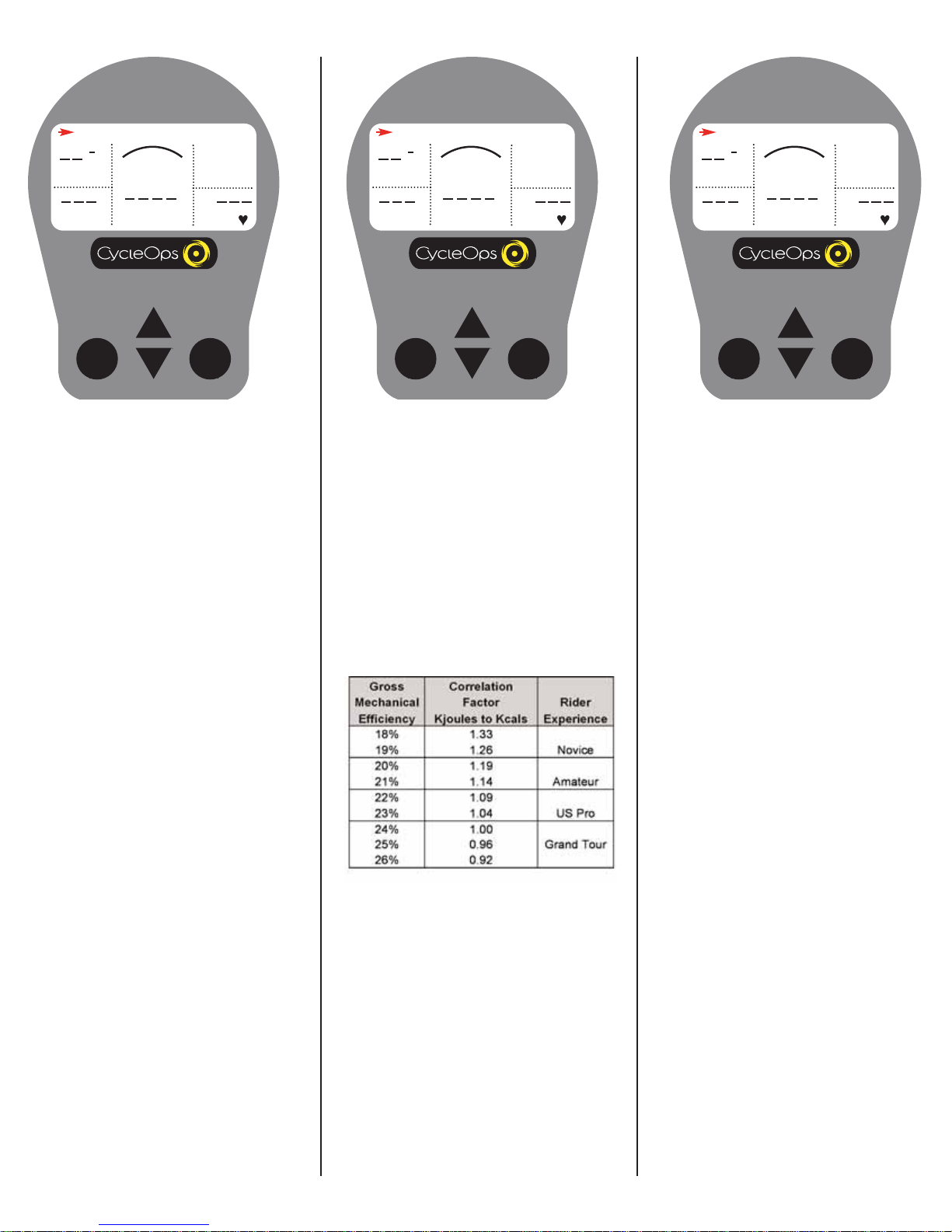
Total energy 0-99999 Kilojoules
Odometer 0-99999 Miles or Kilometers
Heart Rate0-255 BPM (Beatsper Minute)
Maximum Rider Weight 300 lbs.
SarisCycling Group,Inc.
Model #:PowerTap SL 2.4
IC:6459A-SL2P401
FCC ID:T8P-SL2P401

4
replacement part not supplied by SarisCycling Group,SarisCycling Group shall not beliablefor any cost,damage,failureor loss caused by theuse of
such unauthorized serviceor parts.
Cautions
Beforestarting any exercise program,consult with your physicianor health professional.Heor shecanhelp establish theexercise frequency,intensity (tar-
get heart rate, power zone) and timeappropriatefor your particular ageand condition.If you haveany painor tightness inyour chest,anirregular heart-
beat, shortness of breath,feel faint or haveany discomfort whileyou exercise,STOP! Consult your physicianbeforecontinuing.
Failureto follow any of these safeguardsmay result ininjury or serioushealth problems.
*Do not removefeet from pedalswhileCycleOpsIndoor Cycleflywheel isinmotion.
*Do not attempt to ridethebikeat high RPM'sor ina standing positionuntil you havepracticed at lower RPM's.
*Do not placefingersor any other objectsinto moving partsof theexercise equipment.
*Keep children and petsaway from theCycleOpsIndoor Cyclewhilethemachine isinuse. Do not allow children to rideontheCycleOpsIndoor Cycle.
Pedal travel ranges aredesigned and intended for adults.
*Never turnpedal crank armsby hand.To avoid entanglement and possibleinjury,do not expose handsor armsto thedrivemechanism.
*Do not dismount theCycleOpsIndoor Cycleuntil both thepedalsand theflywheel areat a completeSTOP.
*After exercising,turntheadjustment control knob clockwise to increase tensionso thepedalswill not rotatefreely and possibly hurt someone.
HeartRate Monitor Strap
Position the heartrate monitor strap on your torso as pictured in figure 1. The strap should restjustbeneath the pectoral
muscles of the chest. Make sure the electrodes on the strap are slightly moistwhere itcontacts the skin for bestresults.
The heartrate strap mustbe worn to enable the heartrate functionality of the Comp 200E and Pro 300PT models.
Bracket
When firstsetting up the CycleOps Indoor Cycle you mustattach the console bracketto the bike. To do this follow the instructions below:
Installation Figure1
A. Placebracket onto thehandlebarsasshownbelow.
B. Insert screwsthrough consolebracket,handlebar bracket,and tighten together.
C. Slideconsoleonto base.
D. Connect theconsolewireto theIndoor Cycleframewireby removing thetwist tieontheindoor cycleframewire.
E. Discard thetwist tie,attach theplastic grommet to theconsolewireasshown.
F. Connect theconsolewireto theindoor cycleframewire.
G. Push connected wireinto theIndoor Cycleframeuntil theplug isinserted completly;then insertplastic grommet
into frame.
AB

5
CD
F
E
GH

6
Console to bracket
To connect the console to the bracket,slide the console down onto the bracket. Be sure to slide the console completely down onto the bracketto ensure
a solid connection between the console and the bracket. Make sure the contact points between the console and bracketremain clean and free from
moisture or debris.
Batteries
The console ships with batteries. In the eventthe batteries need to be replaced over time,follow these simple steps:
1.Remove the back cover with a small philips head screwdriver
2.Remove batteries
3.Replace with fresh AAA batteries,paying attention to properly line up the poles
4.Replace battery door and secure with small philips head screwdriver
Reed Switch The Comp 200E is
equipped with a
reed switch locat-
ed on the leftrear
dropout.
This switch picks up the speed and cadence readings from the flywheel. In the eventthe switch needs to be replaced,follow these steps:
1.Remove the existing reed switch from the frame by peeling itfrom the inside of the dropout.
2.Detach the switch from the frame wire by depressing the pinch lock and sliding the two connecters apart.
3.Attach the new switch on the inside of the rear,leftdropoutwith the included double stick tape.
4.Slide the connecters together,making sure to align the pinch lock with the locking tooth on the frame wire. Tuck any slack in the cable
back inside the stay.
PT Receiver
The Pro 300PT is equipped with a PowerTap receiver on the rear leftdropout. This receiver receives the speed,cadence and power data from the
PowerTap flywheel. In the eventyou need to replace the PowerTap receiver,follow these steps:
1.Remove the existing receiver by loosening the plasticscrews,paying attention to loosen the square nuts on the inside of the dropout.
2.Detach the receiver from the frame wire by depressing the pinch lock and sliding the two connecters apart.
3.Attach the new receiver to the dropoutwith the plasticscrews and square nuts (PIC).
4.Slide the connecters together,making sure to align the pinch lock with the locking tooth on the frame wire. Tuck any slack in the cable
back inside the stay.
IMPORTANT! How To Zero Torque
The torque mustbe zeroed to ensure thatthe PowerTap displays the mostaccurate power information. If the instantaneous power is positive,or nega-
tive,the torque needs to be zeroed. These operations mustbe done with NO tension on the chain or while stationary with NO force being placed on the
pedals. Also,the transmission icon mustbe illuminated.
To zero torque firstensure the transmission icon is showing then press [DOWN ARROW] to move the cursor to [WATTS]. Press [SELECT] to change to
[INCH-LBS]. Then hold down [SELCT] again until "0" is shown. Press [SELECT] to return to [WATTS]. The torque value will now read zero.

7
Console Navigation
UPand DOWN ARROWS
[UPARROW] and [DOWN ARROW] are used
to scroll through the differentfields on the
console. [UPARROW] and [DOWN ARROW]
can also be used to move the navigation
cursor on the [MAIN MENU]. Additionally,
these arrows are used to increase or
decrease values when establishing user pro-
file features.
MODE and SELECT Buttons
Use [MODE] to toggle between different
menu options and to enter the interval
mode (See [INTERVAL MODE] for further
details). Use [SELECT] to enter a new menu
screen. Italso functions as an "enter" func-
tion to escape a screen after making your
selection.
SELECT
MODE
Display Definitions
(ScrollingTop Bar)
SCROLLING TOP BAR - From the dashboard
display press [UPARROW] or [DOWN
ARROW] to move the cursor to the top bar
and press [SELECT] to toggle through func-
tions.
RIDE TIME 00:00:00
MPH
CAD
MENU
WATTS HR
H
SELECT
MODE SELECT
MODE
Distance
DISTANCE - Total trip or interval distance is
displayed in miles or kilometers from 0.00
to 999.99. Distance displays in the same
units as speed.
DISTANCE 0.00
MPH
CAD
MENU
WATTS HR
H
Console Navigation FunctionsDashboard Display

8
SELECT
MODE
RideTime
Total time thatthe user has ridden the
bike. Time is displayed in (hours :minutes :
seconds).
RIDE TIME 00:00:00
MPH
CAD
MENU
WATTS HR
H
SELECT
MODE
Energy in KJ
This value is a measure of the total work
done over the course of your ride. Power is
displayed in watts and is a measure of the
intensity of work. Energy is calculated using
the following equation. See Table 1 for an
accurate estimate of Kjoules to Kcal conver-
sion.
Work or Energy (Joules) = Watts (Power) x
Time (Seconds)
ENERGY IN KJ 0
MPH
CAD
MENU
WATTS HR
H
SELECT
MODE
Odometer
Thisisarollingtallyofthedistancethatyou
have ridden the CycleOps Indoor Cycle.
Thiscanbe displayed inMiles orKilometers
(see "Settings (Recording Rate,Speed,
Odometer,Audible)" for details).
ODOMETER 255
MPH
CAD
MENU
WATTS HR
H
Estimated CaloricCorrelation Factor- For an
accurate estimate of Kcals,multiply the
[ENERGYINKJ]bythecorrelationfactorbest
describing your riding experience.
Table 1

9
SELECT
MODE
MAX,AVG,and CURRENT Field
This line displays the current, maximum or average values for the ride or interval. From the dashboard display,press [UPARROW] or [DOWN ARROW] to
move two spaces above [MENU]. Press [SELECT] to toggle between [MAX],[AVG],and currentreadings.Currentreadings are displayed when field is blank.
CLOCK 02:06:07P
MPH
CAD
MENU
WATTS HR
H
SELECT
MODE
Clock
Areal-timedisplayof thecurrenttimeofthe
day (see "Setup (Time and Date)" for details)
CLOCK 02:05:28P
MPH
CAD
MENU
WATTS HR
H
MAX
00
000
SELECT
MODE
Average
CLOCK 02:06:07P
MPH
CAD
MENU
WATTS HR
H
AVG
00
000
SELECT
MODE
Current
CLOCK 02:05:28P
MPH
CAD
MENU
WATTS HR
H
SELECT
MODE
TRANSMISSION ICON
When this icon is showing,there is a signal
transmitting from the hub to the receiver.
CLOCK 02:05:28P
MPH
CAD
MENU
WATTS HR
H
Maximum

10
SELECT
MODE
Interval Mode
The console works as a lap marker,and is
essentially always on.
1) From any location on the dashboard dis-
play press and release [MODE] and
[SELECT] simultaneously. [INT] and the
newinterval#willbrieflyappearbeforedis-
appearing again to the background in the
field located above [MENU].
CLOCK 02:06:07P
MPH
CAD
MENU
WATTS HR
H
SELECT
MODE
Tachometer
This functions as a visual interpretation of
how hard you are working compared to a
fixed wattage value. From the dashboard
display press [UPARROW] or [DOWN
ARROW] to move the cursor to [H]. Press
[SELECT] tochange the maximum tachome-
ter value (400,600,800 or 1000 watts).
CLOCK 02:06:07P
MPH
CAD
MENU
WATTS HR
H
SELECT
MODE
Watts
Real-time display of the currentwattage
placed on the flywheel. This is your power
reading. Watts is derived from the follow-
ing equation:
Watts (Power) =Torque xAngularVelocity
CLOCK 02:06:07P
MPH
CAD
MENU
WATTS HR
H
00
000
SELECT
MODE
Watts INCH-LBS
NOTE: If you press [SELECT] while the cur-
sor is pointing to [WATTS] the line changes
to [INCH-LBS]. This is the raw torque value
thatis being applied to the hub,NOT your
power in watts.
CLOCK 02:06:07P
MPH
CAD
MENU
INCH-LBS HR
H
SELECT
MODE
Interval Mode
2)To view intervalspecificdata inthe dash-
boarddisplay press [UPARROW] or[DOWN
ARROW]untilthecursoriconisinthespace
above [MENU]. Press and hold [MODE] for
two (2) seconds. This brings interval mode
to the foreground and [INT] and the inter-
valnumberwillconstituteathirdlinein the
display.
CLOCK 02:06:07P
MPH
CAD
MENU
WATTS HR
H
INT: 1
SELECT
MODE
Interval Mode
3) When you wish to relegate the interval
information to the background press
[MODE] for two (2) seconds
CLOCK 02:06:07P
MPH
CAD
MENU
WATTS HR
H
INT: 1

11
SELECT
MODE
Interval Memory Mode
1) To access stored interval information
press [UPARROW] or [DOWN ARROW] to
scroll to the interval line (See Interval
Mode) and hold [MODE] for two (2) sec-
onds. Thisbringsintervalmodetothe fore-
ground. Press [MODE] to move interval
numbers up,and [SELECT] to move interval
numbersdown.Currentintervalsreadblack
[INT] and memory intervals read white
[INT] in a black box.
CLOCK 02:06:07P
MPH
CAD
MENU
WATTS HR
H
INT: 2

12
SELECT
MODE
Console Setup 1
1) From the dashboard display press [UP
ARROW] or [DOWN ARROW] to move the cur-
sor to [MENU] and press [SELECT].
CLOCK 02:06:07P
MPH
CAD
MENU
WATTS HR
H
Console Setup
SELECT
MODE
Console Setup 2
2) Press [SELECT] to enter [RETURN TO
RIDE].
MAIN MENU
RETURN TO RIDE
SETUP USER RIDE
CLEAR MEMORY
TEST
SETUP
SELECT
MODE
Console Setup 3
3) Press [DOWN ARROW] to scroll through
six(6) [USER] files and press [SELECT] to
choose the user. (See "Setting User
Information" to establish a user profile).
RETURN TORIDE
1 USER A
2 USER B
3 USER C
4 USER D
5 USER E
6 USER F
Console Setup 4
4) Press [DOWN ARROW] to choose ride
type and press [SELECT] to return to dash-
board display.
RideType Selection
Press any button to wake up and turn on the
console. If you are using itfor the firsttime,
all data will be stored under [USERA] with
thedefaultsettingsfora150lbmalebornon
Jan 1,2004. You may need to resetthe con-
sole if there is data from a previous ride
stored on the console (see "Clear Memory"
for details). NOTE:Parameterssuchasweight
andagedonotaffectpoweroutputreadings
on the console. These settings apply only
when analyzing the data on your PC.
SELECT
MODE
RIDE TYPE
CYCLE COMPUTER
POWER ZONE
HEART RATE ZONE

13
Setup User Information 1
1) From [MAIN MENU] press [DOWN
ARROW] to scroll to [SETUPUSERRIDE] and
press [SELECT].
SELECT
MODE
MAIN MENU
RETURN TO RIDE
SETUP USER RIDE
CLEAR MEMORY
TEST
SETUP
Setup User Information 2
2) Press [DOWN ARROW] to scroll to [USER]
files and press [SELECT] to chose a user.
(See "Setting User Information" to establish
a user profile).
SELECT
MODE
CYCLE COMPUTER
POWER ZONE
HEART RATE ZONE
USER INFORMATION
SETTINGS
RETURN
Setting User Information
Thisoptionallowsyoutosetthepersonalprofile
of up to sixdifferentindividuals.
Setup User Information 3
3) Press [DOWN ARROW] to scroll to [USER
INFORMATION] and press [SELECT].
4) Press [SELECT] and [UPARROW] or
[DOWN ARROW] to enter letters. Press
[SELECT] to toggle through letters. Press
[SELECT] to acceptchanges and reenter
scrolling menu.
Setup User Information 4
5) Repeatstep 3 to set[BRITH DATE],
[WEIGHT],and [GENDER] information.
NOTE: This data does notaffect console
power data.
6) To resetuser settings,press [DOWN
ARROW] to scroll to [RESET] and press
[SELECT].
SELECT
MODE
USER INFORMATION
NAME
USER A
BIRTH DATE 05-01-43
WEIGHT 199
GENDER MALE
RESET
RETURN
SELECT
MODE
USER INFORMATION
NAME
USER A
BIRTH DATE 05-01-43
WEIGHT 199
GENDER MALE
RESET
RETURN
Setup User Information 5
7)To begin a ride,press [DOWN ARROW] to
scroll to [RETURN] and press [SELECT].
Press[DOWNARROW]to scroll to[RETURN]
and press [SELECT].
SELECT
MODE
USER INFORMATION
NAME
USER A
BIRTH DATE 05-01-43
WEIGHT 199
GENDER MALE
RESET
RETURN

14
Power Zone 5
5) Press [DOWN ARROW] to scroll to [ZONE
1] and press [SELECT] to enter the upper %
trainingzone. Press[UPARROW]or[DOWN
ARROW] to adjustvalueandpress[SELECT]
to reenter the scrolling menu.
SELECT
MODE
Power Zone 4
4) Press [SELECT] to manually inputa previ-
ously determined anaerobicthreshold (AT)
value (displayed in watts) for which % val-
ues will be based.Press [SELECT] to toggle
through digitvalues. Press [SELECT] to
reenter scrolling menu.
Power Zone 2
2) Press [DOWN ARROW] to scroll through
six(6) [USER] files and press [SELECT] to
select a user file. (See "Setting User
Information" to establish a user profile).
Power Zone 3
3) Press [DOWN ARROW] to scroll to
[POWERZONE]. Press [SELECT] to enter
Power Zone 1.
SELECT
MODE
RETURN TORIDE
1 USER A
2 USER B
3 USER C
4 USER D
5 USER E
6 USER F
SELECT
MODE
RIDE TYPE
CYCLE COMPUTER
POWER ZONE
HEART RATE ZONE
POWER ZONE 1
ANAR TH 450
ZONE 1 0%-55%
ZONE 2 55%-75%
ZONE 3 75%-90%
ZONE 4 90%-105%
NEXT ZONE
RETURN
SELECT
MODE
POWER ZONE 1
ANAR TH 450
ZONE 1 0%-55%
ZONE 2 55%-75%
ZONE 3 75%-90%
ZONE 4 90%-105%
NEXT ZONE
RETURN
SELECT
MODE
Power Zone 1
1) From [MAIN MENU] press [DOWN
ARROW] to scroll through to [SETUPUSER
RIDE] and press [SELECT].
MAIN MENU
RETURN TO RIDE
SETUP USER RIDE
CLEAR MEMORY
TEST
SETUP
Power Zone Based
Ride Setup
Power zones separate your power data into
discrete bins,or intervals,specificto a par-
ticularenergyorphysiologicalsystem.From
shortmaximal efforts to long maximal
efforts these energy systems run along a
continuumfromanaerobictoaerobicmeta-
bolicpathways.These bins help to separate
these efforts to better quantify your train-
ing stimulus.

15
Power Zone 8
9) To resetdefaultzone settings,press
[DOWN ARROW] to scroll to [RESET] and
press [SELECT].
10)To begin apowerzone based ride,press
[DOWN ARROW] to scroll to [RETURN] and
press [SELECT]. Press [DOWN ARROW] to
scroll to [RETURN] and press [SELECT] once
again.
SELECT
MODE
POWER ZONE 2
ZONE 5 105%-120%
ZONE 5 120%-133%
ZONE 5 133%-165%
PREVIOUS ZONE
RESET
RETURN
Power Zone 7
8) In Power Zone 2 screen repeatsteps 3,4,
and 5 to setinformation for [ZONE 5-6].
SELECT
MODE
POWER ZONE 2
ZONE 5 105%-120%
ZONE 5 120%-133%
ZONE 5 133%-165%
PREVIOUS ZONE
RESET
RETURN
Power Zone 6
6) Press [DOWN ARROW] and then press
[SELECT] to adjust[ZONE 2]. Repeatsteps
3,4,and 5 to set[ZONES2-4]. NOTE: The
lower%trainingzonewill automatically set
to the previous zone's upper limit.
7) Once [ZONE 1-4] information has been
set, press [DOWN ARROW] to scroll to
[NEXT ZONE] and press [SELECT].
SELECT
MODE
POWER ZONE 1
ANAR TH 450
ZONE 1 0%-55%
ZONE 2 55%-75%
ZONE 3 75%-90%
ZONE 4 90%-105%
NEXT ZONE
RETURN

16
Heart Rate Zone 3
3)Press[DOWNARROW]toscrollto[HEART
RATE ZONE] and press [SELECT].
Heart Rate Zone 2
2) Press [DOWN ARROW] to scroll to [USER]
files and press [SELECT] to chose a user.
(See "Setting User Information" to establish
a user profile).
Heart Rate Zone 4
4) Press [SELECT] and press [DOWN
ARROW] to toggle between [AT] or [MAX]
settings. Press [SELECT] to reenter scrolling
menu. NOTE: [AT] sets % heartrate values
to be based off a previously determined AT
test, and [MAX] sets % heartrate values to
bebased off either a predicted or previous-
ly determined MAX heartrate value.
Heart Rate Zone 1
1) From [MAIN MENU] press [DOWN
ARROW] to scroll to [SETUPUSERRIDE] and
press [SELECT].
Heart Rate Zone 5
5) Select [ANARTH] to setthe heartrate
value for which % values will be based.
Press [SELECT] to toggle through digitval-
ues. Press [SELECT] to acceptchanges and
reenter scrolling menu.
SELECT
MODE
HEART RATE ZONE
TYPE MAX
ANAR TH 162
ZONE 1 50%-83%
ZONE 2 83%-91%
ZONE 3 91%-93%
ZONE 4 93%-160%
RESET RETURN
SELECT
MODE
MAIN MENU
RETURN TO RIDE
SETUP USER RIDE
CLEAR MEMORY
TEST
SETUP
SELECT
MODE
RETURN TORIDE
1 USER A
2 USER B
3 USER C
4 USER D
5 USER E
6 USER F
SELECT
MODE
CYCLE COMPUTER
POWER ZONE
HEART RATE ZONE
USER INFORMATION
SETTINGS
RETURN
SELECT
MODE
HEART RATE ZONE
TYPE MAX
ANAR TH 162
ZONE 1 50%-83%
ZONE 2 83%-91%
ZONE 3 91%-93%
ZONE 4 93%-160%
RESET RETURN
Heart Rate Zone Based
Ride Setup
Heartrate zones separate your heartrate data
into discrete bins,or intervals,specificto a par-
ticular energy or physiological system. From
shortmaximal efforts to long maximal efforts
these energy systems run along a continuum
from anaerobicto aerobicmetabolicpathways.
These bins help to separate these efforts to bet-
ter quantify your training stimulus.

17
Heart Rate Zone 6
6) Press [DOWN ARROW] and [SELECT] to
adjust[ZONE 2]. Continue this process to
set[ZONES1-4]. NOTE: The lower % train-
ing zone will automatically setto the previ-
ous zone's upper limit.
Heart Rate Zone 7
7) To resetdefault[ZONE] settings select
and press [RESET].
8)To begin a ride,press [DOWN ARROW] to
scroll to [RETURN] and press [SELECT].
Press[DOWNARROW]to scroll to[RETURN]
and press [SELECT].
SELECT
MODE
HEART RATE ZONE
TYPE MAX
ANAR TH 162
ZONE 1 50%-83%
ZONE 2 83%-91%
ZONE 3 91%-93%
ZONE 4 93%-160%
RESET RETURN
SELECT
MODE
HEART RATE ZONE
TYPE MAX
ANAR TH 162
ZONE 1 50%-83%
ZONE 2 83%-91%
ZONE 3 91%-93%
ZONE 4 93%-160%
RESET RETURN

18
Settings 3
3) Press [DOWN ARROW] to scroll to [SET-
TINGS] and press [SELECT].
Settings 2
2) Press [DOWN ARROW] to scroll to [USER]
files and press [SELECT] to enter the file.
(See "Setting User Information" to establish
a user profile).
Settings 4
4) Press [SELECT] to enter [COMPUTER]
mode.
Settings 1
1) From [MAIN MENU] press [DOWN
ARROW] to scroll to [SETUPUSERRIDE] and
press [SELECT].
Settings 5
5) Press [SELECT] to enter [RATE]. Use [UP
ARROW] or [DOWN ARROW] to toggle
between 1,2,5,10,30 seconds for the
recording rate of the console. Press
[SELECT] to acceptchanges and reenter
scrolling menu. NOTE: Differentrecording
rates yield differentamounts of total stor-
agetime. Refertothecharton lefttoselect
the mostappropriate storage rate. See
Table 2 atleft.
SELECT
MODE
SETTINGS
COMPUTER
AVERAGE
ZEROS
RETURN
SELECT
MODE
CYCLE COMPUTER
POWER ZONE
HEART RATE ZONE
USER INFORMATION
SETTINGS
RETURN
SELECT
MODE
MAIN MENU
RETURN TO RIDE
SETUP USER RIDE
CLEAR MEMORY
TEST
SETUP
SELECT
MODE
COMPUTER
RATE 10
MPH-KPH MPH
ODOMETER 00255
AUDIBLE OFF
RETURN
Settings (Recording
Rate,Speed,Odometer,
Audible)
SELECT
MODE
RETURN TORIDE
1 USER A
2 USER B
3 USER C
4 USER D
5 USER E
6 USER F
Table 2

19
Settings 9
10) To begin a ride,press [DOWN
ARROW] to scroll to [RETURN] and
press [SELECT]. Press [DOWN ARROW]
to scroll to [RETURN] and press
[SELECT].
Settings 8
9) Press [DOWN ARROW] and scroll to
[AUDIBLE] and press [SELECT]. Use [UP
ARROW] or [DOWN ARROW] to toggle
between [ON] and [OFF] and press
[SELECT] to acceptchanges and reenter
scrolling menu.
Settings 6
6) Press [DOWN ARROW] to scroll to [MPH-
KPH] and press [SELECT].
7) Press [DOWN ARROW] to toggle
between [MPH] and [KPH] and press
[SELECT] to reenter scrolling menu.
Settings 7
8) Press [DOWN ARROW] and scroll to
[ODOMETER] and press [SELECT]. Use [UP
ARROW] or [DOWN ARROW] to manually
enter the starting odometer reading. Press
[SELECT] to toggle through digitvalues.
Press [SELECT] to reenter the scrolling
menu.
SELECT
MODE
COMPUTER
RATE 10
MPH-KPH MPH
ODOMETER 00255
AUDIBLE OFF
RETURN
SELECT
MODE
COMPUTER
RATE 10
MPH-KPH MPH
ODOMETER 00255
AUDIBLE OFF
RETURN
SELECT
MODE
COMPUTER
RATE 10
MPH-KPH MPH
ODOMETER 00255
AUDIBLE OFF
RETURN
SELECT
MODE
COMPUTER
RATE 10
MPH-KPH MPH
ODOMETER 00255
AUDIBLE OFF
RETURN

20
Settings (Averages)
These settings allow for better pacing during
TimeTrialeffortsbyallowingforaslowerupdate
of the display. Changing these settings applies
only the display console and does notaffect the
recording rate for download
Setting (Averages) 1
1) From [MAIN MENU] press [DOWN
ARROW] to scroll to [SETUPUSERRIDE] and
press [SELECT].
Setting (Averages) 2
2) Press [DOWN ARROW] to scroll through
six(6) [USER] files and press [SELECT] to
select a user file. (See "Setting User
Information" to establish a user profile).
SELECT
MODE
MAIN MENU
RETURN TO RIDE
SETUP USER RIDE
CLEAR MEMORY
TEST
SETUP
SELECT
MODE
RETURN TORIDE
1 USER A
2 USER B
3 USER C
4 USER D
5 USER E
6 USER F
Setting (Averages) 5
5) Press [SELECT] to enter [WATTSAVG].
Press [UPARROW] or [DOWN ARROW] to
determine the number of previous data
points used (1,2,3,5,10,30) to determine
the average metricdisplay on the console.
This function applies only to console data
averages and does notapply to down-
loaded information. Press [SELECT] to
acceptchanges and reenter the scrolling
menu.
Setting (Averages) 3
3) Press [DOWN ARROW] to scroll to [SET-
TINGS] and press [SELECT].
Setting (Averages) 4
4) Press [DOWN ARROW] to scroll to [AVER-
AGE] and press [SELECT].
SELECT
MODE
AVERAGE
WATTS AVG 2
SPEED AVG 3
CADENCE AVG 5
HEART AVG REGULAR
TORQUE AVG 1
RESET
RETURN
SELECT
MODE
CYCLE COMPUTER
POWER ZONE
HEART RATE ZONE
USER INFORMATION
SETTINGS
RETURN
SELECT
MODE
SETTINGS
COMPUTER
AVERAGE
ZEROS
RETURN
Other manuals for Club Pro 300PT
2
Table of contents
Other CycleOps Exercise Bike manuals

CycleOps
CycleOps 400 Pro Series User manual

CycleOps
CycleOps Magnus User manual

CycleOps
CycleOps 400 Pro Series User manual

CycleOps
CycleOps Club Pro 300PT User manual

CycleOps
CycleOps Club IC User manual

CycleOps
CycleOps Club Pro 300PT User manual

CycleOps
CycleOps 100 PRO User manual

CycleOps
CycleOps Phantom series User manual

CycleOps
CycleOps JetFluid Pro User manual

CycleOps
CycleOps Hammer User manual