CycleOps Club IC User manual

1
Club IC Assembly Service Manual
CHAPTERS:
1. UNPACKING THE CYCLEOPS INDOOR CYCLE.......1
2. BIKE ASSEMBLY.............................................................1
3. GENERAL USE................................................................4
3. COMMON ADJUSTMENTS.........................................6
4. LUBRICATION................................................................8
5. ELECTRONICS INSTALLATION...................................9
6. USB STICK.......................................................................10
7. RF INTERFERENCE.........................................................10
8.WARRANTY......................................................................10

1
CHAPTER 1: UNPACKING THE INDOOR CYCLE
Place the box upright and cut the plastic binding straps. Lift the top of the box to expose the Indoor Cycle and packaging. Re-
move all parts from the box and foam inserts and ensure all the following parts are included:
Part Qty
Stabilizer front 1
Stabilizer rear 1
Main bike assembly 1
Handlebar tube 1
Seat post tube 1
Saddle w/ clamp 1
Seat assembly 1
Handlebar 1
Water bottle holder 1
Pedalset 1
IP hardware kit 1
Stabilizer bolts 8
Stabilizer bolt washers 8
Console Bracket bolts 2
Water bottle spacer 1
Spacer bolts 2
Multi-purpose wrench 1
5mm allen wrench 1
4mm allen wrench 1
Console Bracket w/ screw (200/300 only) 1
Console (200/300 only) 1
CHAPTER 2: BIKE ASSEMBLY
Step 1: Attach Stabilizer Feet
1. Note the difference between the front and rear stabilizer feet. The larger foot with wheels goes in the rear of the IC.
2. Align the rear base of the frame with the rear stabilizer and secure it with four 6mm bolts with washers. NOTE:Tighten
the inner bolts first, and then proceed to the outer bolts to ensure the foot is secured properly and evenly.
3. Repeat with the front stabilizer.
Front Stabilizer Feet
Rear Stabilizer Feet

2
Step 2: Attach Handlebars
Step 3: Attach Seat/Seat Post
Insert the Handlebar post into the head
tube and secure it using the pull-pin.
Slide the plastic shim onto the D-shaped
tube on the water bottle holders.
Slide the water bottle holder and plastic
spacer onto the handlebar assembly.
Affix water bottle holders and spacer to
handlebar assembly via 2- 4mm allen
bolts
Carefully slide the handlebar onto the
handlebar post. Once the handlebar is in place,
secure it with the L-shaped
tension handle.
Insert the seat post tube into the indoor
cycle and secure it using the pull-pin.
Attach the saddle to the saddle clamping
assembly. Slide the saddle clamp onto
the knurled post, making sure the nose
of the saddle and the knurled post point
in the same direction. Finger-tighten the
14mm clamping nut.
Slide the saddle assembly with saddle
onto the seat post tube.

3
Step 3: Attach Seat/Seat Post Cont. Step 4: Attach Pedals
Step 5: Electronics
See CONSOLE section
Bracket
When first setting up the CycleOps Club Indoor Cycle you must attach the console bracket to the bike.To attach console
to bike, follow the instructions below:
Align the saddle so that it is level and
parallel to the floor for optimum com-
fort. Use a 14mm wrench to tighten the
saddle. Make sure you tighten both sides
to ensure a secure connection between
the saddle clamp and the knurled post.
Install the pedals with the included multi-purpose wrench. The toe baskets must
point towards the front of the indoor cycle. Note that pedals are designed to be
installed specifically on the right or left-hand side of the IC. Improper installation can
result in damage to the crank. Damage caused by improper pedal installation is not
covered under warranty NOTE: Pedals are designed to be installed on a specific side of
the indoor cycle.Turn the left pedal spindle counterclockwise when installing it into
the crank arm. Turn the right pedal clockwise when installing it into the crank arm.
Slide console onto bracket. Use included screw to secure the console
to the console bracket(optional). Place bracket onto
the handlebars as
shown. Insert 3mm screws through
console bracket, into handlebar
bracket and tighten.

4
Batteries: The console ships with batteries. In the event the batteries need to be replaced over time, follow these simple steps:
Leveling the bike
Once the above assembly instructions have been followed, move the bike to where it will be used and level it properly.To level the
bike, adjust the leveling feet underneath the stabilizers until there is no rocking or movement of the bike.
CHAPTER 3: GENERAL USE
Remove the back cover with a small Philips head screwdriver
Remove batteries
Replace with fresh AAA batteries, paying attention to properly line up the +/- poles
Replace battery door and secure with small Philips head screwdriver
You can secure the feet by tightening the
leveler locks
Leveler Lock
The CycleOps Indoor Cycle is easy to use. Simply sit on the cycle, tighten the pedal straps and begin cycling.The CycleOps indoor
cycle allows the user full control over resistance by simply adjusting the resistance knob.Typically, lower resistance levels enable
you to pedal at a faster pace, placing increased demand on the cardiovascular system. Higher resistance levels will typically deliver
a greater muscle/endurance workout at lower RPMs. RPM parameters in the program range from 60-110 RPM.
Additionally, the indoor cycle offers seat and handlebar adjustments, allowing the CycleOps indoor cycle to be configured to each
user’s comfort zone.
This section provides the instructions for making seat adjustments,
handlebar adjustments, pedal strap adjustments, and for controlling resistance.
Seat Adjustments
Proper seat height helps ensure maximum exercise efficiency and comfort, while
reducing the risk of injury. Adjust the seat height so that the knee joint is slightly
flexed when the extended leg is at the bottom of the pedal stroke.Once the proper
height has been achieved, adjust the seat forward or back so that when the feet are
in the 3 o’clock and 9 o’clock positions, the knees are directly over the pedal spindle.

5
To adjust the seat height:
Dismount the cycle.Turn the seat height pop-pin counterclockwise and pull out on
the pin to release it from its current preset location. Raise or lower the seat to the
desired height, then gently release the pop-pin. Raise or lower the seat slightly, if
necessary, until the pop-pin engages a preset hole.Turn the pop-pin clockwise to
secure.
To adjust the seat horizontal position:
Dismount the indoor cycle. Loosen the seat fore-and-aft tension handle by turning
the handle counterclockwise. Move the seat forward or back to the desired posi-
tion, then tighten the tension handle by turning clockwise. Be sure to tighten the
handle firmly.
Handlebar Adjustments
Proper position for the handlebar is based primarily on comfort.Typically, the
handlebar should be positioned even with or slightly higher than the seat.
Dismount the indoor cycle Turn the handlebar height pop-pin counterclockwise
and pull out on the pin to release it from its current preset location. Raise or lower
the handlebar to the desired height, then gently release the pop-pin. Raise or lower
the handlebar slightly, if necessary, until the pop-pin engages a preset hole.Turn
the pop-pin clockwise to secure.
To adjust the handlebar horizontal position:
Dismount the indoor cycle. Loosen the handlebar fore-and-aft tension handle by
turning the handle counterclockwise. Move the handlebar forward or back to the
desired position, then tighten the tension handle by turning clockwise. Be sure to
tighten the handle firmly. As a general guideline, handlebar fore-and-aft can be
determined by placing one’s elbow on the nose of the saddle and extending the
fingers straight. Adjust handlebar fore-and-aft until the fingertips touch the handle-
bar near the stem and tighten.
Pedal Strap Adjustment
The pedal straps should be adjusted to hold the foot snugly in the pedal.
To adjust the pedal straps:
Place each foot in the toe clip until the ball of the foot is over the pedal axle.The
front of the shoe may not completely fill the toe cage.Rotate the pedals until one
foot is within arms reach, then tighten the webbed cloth buckle until the cage of
the toe clip is snug around the foot.Repeat for the other foot. Point your toes and
knees directly forward to ensure maximum pedal efficiency.
Resistance Control
Pedaling resistance is controlled by the resistance knob located behind the handle-
bar. Resistance adjustments can be made while riding to vary the intensity of your
workout.
To adjust pedaling resistance:
To increase resistance, turn the knob clockwise (+); to decrease resistance, turn the
knob counterclockwise (-).
In case of emergency, you may press directly down on the knob to bring the fly-
wheel to an abrupt stop.
POP-PIN
Fore-aft
Handle
POP-PIN
Fore-aft
Handle

6
CHAPTER 4: COMMON ADJUSTMENTS
Flywheel Adjustment
Chain tension/Flywheel Alignment
Over time, the chain on your CycleOps Indoor Cycle will stretch due to the load applied to it. The following instructions will aid you
in properly tensioning the chain and aligning the flywheel in the frame of the CycleOps Indoor Cycle. CAUTION: Improper chain
adjustment will cause premature wear and may void the warranty. ** CAUTION NEVER put hands into or near the drive train while
it is motion! **
Move the crank arms back and forth. If
there is more than 1/2”movement in the
chain before the flywheel rotates, the
chain needs to be re-adjusted.
Using a 3mm Allen wrench, remove the
chain guard bolts (3).
Use a 17mm cone wrench to hold the
axle locking nuts into place. Do not turn
the wrench, it is only to be used as a sta-
bilizer.With your other hand, use a 15mm
box wrench to loosen the acorn nuts on
the axle. Repeat this process on each side
of the flywheel.
Once the acorn nuts are loose, you can ad-
just the alignment of the flywheel as well
as the chain tension. Using a 10 mm box
wrench, adjust the tensioning hardware
until the desired chain tension is achieved
evenly on both sides.
Check the alignment of the flywheel
against the seat post of the CycleOps
Indoor Cycle. Once the proper tension
had been achieved and the flywheel is
properly aligned, tighten the Acorn nuts
to 75 in-lbs.
NOTES:
Be sure to make small adjustments to the drive train. Adjust both sides of the tensioning hardware. Only adjusting one side will
lead to improper flywheel alignment and unwanted drive train wear and/or noise. Adjusting the tension/alignment is a difficult
task and improper adjustment can lead to premature chain/cog wear.This is not covered under warranty. The chain tension has
been adjusted properly when there is little or no play felt when the pedals are rocked back and forth.
1/2”
1/2”
Axle
Locking
Nut
Acorn Nut
10 mm chain
tension

7
Replacing Hub Batteries (AA type)
Over time, the batteries that power the electronics in the hub will need to be changed. The split battery cap on the Club Pro 300PT
flywheel was designed to make this task as easy as possible. When it is necessary to change the hub batteries, follow these steps:
Brake Adjustment
The brake mechanism on your CycleOps indoor cycle has been adjusted at the factory. However, over time due to chain stretch
and brake pad wear, it may need to be adjusted. To replace/adjust brake pad, use the following procedure:
Rotate the flywheel to a position where you can access the Allen bolt on the handle
side of the battery cap.
Using a 2.5 mm Allen wrench, remove the screw on the battery cap
Pull the plastic battery cap out via the molded handle.
Replace the batteries, paying close attention to the polar orientation of the batteries.
Replace the battery cap and tighten the set screw.
Back off resistance until it the knob stops
turning (counter-clockwise). Then turn
clockwise 180 degrees (1/2 turn)
Loosen the clamping bolt with an
Allen wrench (*Note, early models use
a 4mm bolt, later models use a 5mm
bolt). Be sure to note the orientation
of all necessary hardware.
Align the brake pad by sliding it
towards the flywheel. Stop when the
pad just touches the flywheel. Note
that you must align the arc of the
brake pad with the arc of the flywheel.
Tighten clamping bolt to 50 in-lbs.
When properly adjusted, the Indoor
cycle should register around 30 watts
at 90rpm with no resistance applied
(can only be validated on Club Pro
300PT)

8
CHAPTER 5: LUBRICATION
Chain
Over time, the chain on your indoor cycle will require additional lubrication. It is
recommended that you lube the chain every six months to maximize chain life.
To lubricate the chain on your indoor cycle, use the lubrication port that is at the
back of the chain guard Liberally spray a Teflon-based lubricant onto the chain.
Be sure each link gets lube. Be careful not to over-lubricate the chain as excess lube
will drip out of the chain guard and can stain floors/carpet.
Nuts & Bolts
It is recommended that you put a light coating of lithium grease on the threads of the
following hardware to ensure proper tightening and to prevent the parts from seizing
over time:
•Stabilizer bolt threads
•Rubber feet threads
•Pull-pin threads
•Pedal spindle threads
Preventative Maintenance
Performing necessary preventative maintenance is key to keeping your CycleOps Indoor Cycle in proper working condition.
Following these recommended maintenance procedures will help extend the life of your CycleOps Indoor Cycle.
DAILY
Wipe Down/Cleaning:
After your ride, be sure to release all tension from the resistance mechanism.Wipe down the entire unit using an absorbent cloth.
A standard bicycle polish can be used on the painted parts of the Indoor Cycle. Focus on areas where sweat can settle. Give par-
ticular attention to the following:
• Handlebar
• Seat/Seat tube
• Flywheel
• Frame
• Chain Guard
• Resistance Knob
• Handlebar Tube
• Stabilizers
**Never use abrasive cleaning liquids or petroleum-based solvents when wiping down the bicycle.
Inspection/Adjustment:
Inspect the CycleOps Indoor Cycle for any loose parts, nuts, bolts, etc.Pay special attention to the
following:
• Pedals
• Seat Assembly bracket
• Handlebar assembly bracket
• Crank arms – tighten to 75 in-lbs.
Lube Part

9
WEEKLY
Perform all daily maintenance recommendations. In addition:
• Inspect screws on console bracket.Tighten if necessary.
• Inspect and properly tighten brake assembly.
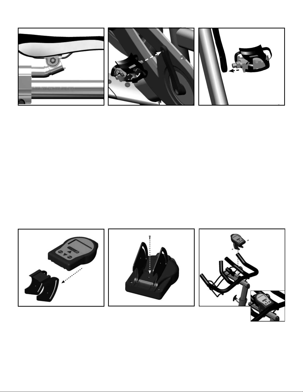
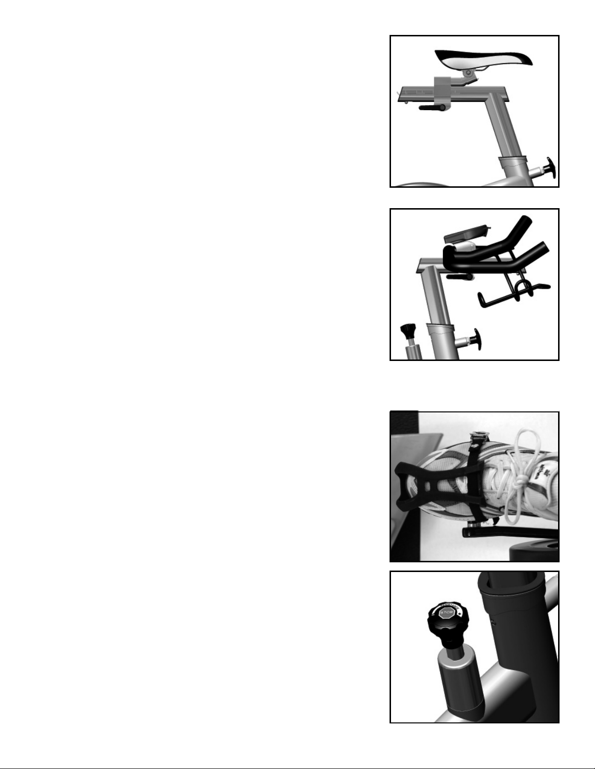
• Properly tighten pedals and all hardware attaching toe clips/straps (if applicable)
• Inspect handlebar clamp assembly. Tighten the water bottle holder in necessary
• Inspect seat clamp assembly. Tighten adjustment bolt if necessary
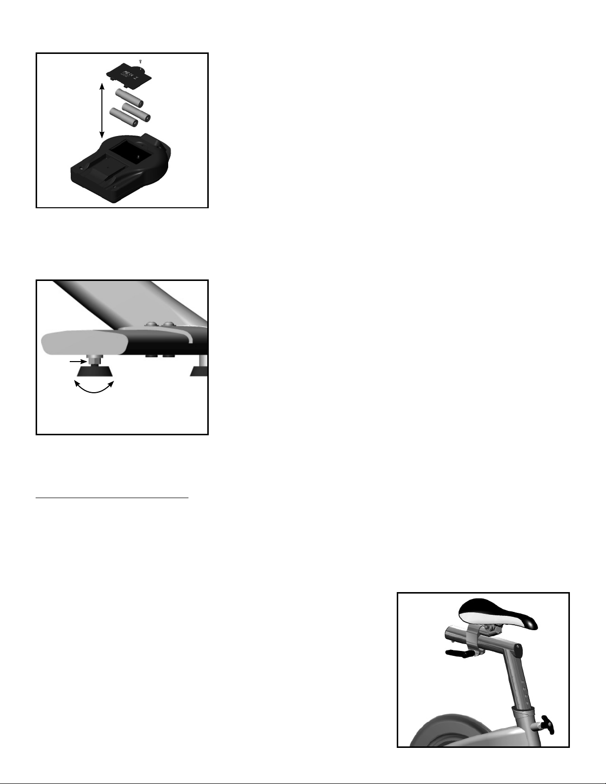
• Inspect stabilizer feet.Tighten if necessary.
• Inspect flywheel. Check for proper alignment.Tighten acorn locking nuts to 75 in-lbs.
• Inspect crank/bottom bracket interface.Tighten to 75 in-lbs
MONTHLY
• Perform all Daily and Weekly maintenance recommendations. In addition:
• Perform thorough cleaning of the CycleOps Indoor Cycle. This includes:
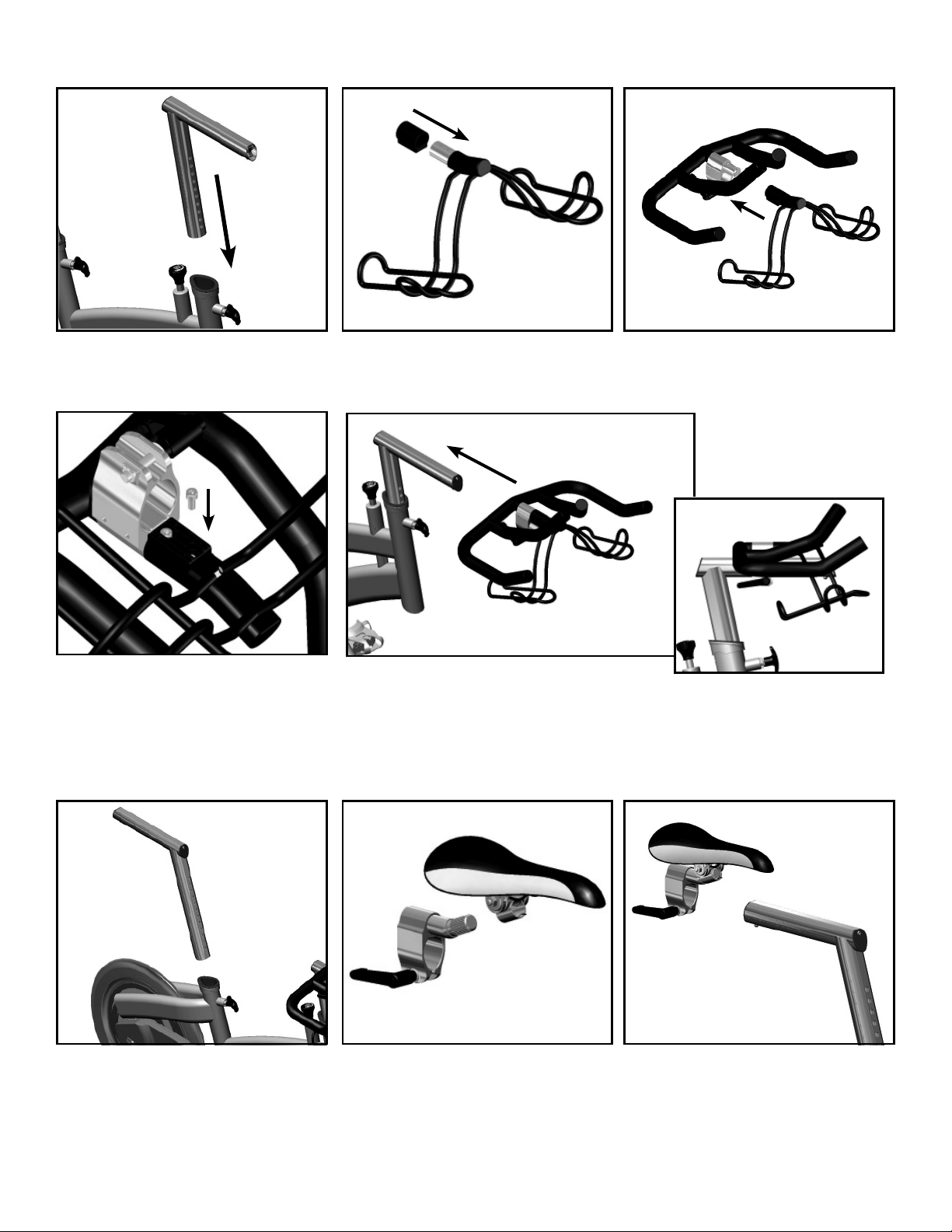
• Remove handlebar tube and seat tube and clean both the stainless steel tube as well as inside the plastic sleeve
• Clean the underside of the stabilizer feet.
• Remove console bracket and clean the handlebar assembly
• Clean the flywheel
• Check the chain tension to ensure that the chain is properly adjusted.See “Adjusting the Chain Tension”for instructions
• Inspect plastic sleeves for damage.Replace if necessary.
• Inspect brake pads for wear. Replace pads if there is less than 2mm of felt pad exposed.
• Lube the drive train. See“Lubrication”for instructions.
CHAPTER 5:
CONSOLE OVERVIEW (200 and 300 bikes only)
Both the Club Comp 200E and Club Pro 300PT are equipped with a handlebar mounted console unit.The console receives a digi-
tally coded signal from the transmitter in the hub of the flywheel. Cadence on the Club Comp 200E as well as Watts and torque on
the Club Pro 300PT are received from the rear hub. In addition to these metrics, the console displays heart rate via a coded telem-
etry signal (chest strap).
SPECIFICATIONS
Accuracy +/-1.5% (Pro 300PT)
Signal Transmission Digital RF
Operational Temperature 0 to 40 degrees c or 32 to 104 f
Battery Life (Hub) 1000 hours approx.
Battery Life (Console) 100 hours approx.
Battery Type (Hub) AA type 1.5 volt 2 ea)
Battery Type (Console) AAA type, 1.5 volt (3 ea)
Freehub fixing bolt torque 400-450 inch-lbs.
ELECTRONICS INSTALLATION
1. See “Bracket” under installation instructions
Console Operation
Begin pedaling and press any button to wake up the console. It may take up to 90 seconds for the console to recognize the hub.
When searching for the hub, the display will show vertical lines in the WATTS field. Once the console finds the hub, biometric data
will be displayed.To simplify the user interface on the console, there are four buttons; they are the UP ARROW, DOWN ARROW,
STATS and RESET. The functions of the buttons are:
UP ARROW: Pressing and releasing the UP ARROW button allows you to select which data metric you would like to view in
bold.
DOWN ARROW: Pressing and releasing the DOWN ARROW button allows you to select which data metric you would like
to view in bold.
RESET:Pressing and releasing the RESET button twice, clears out all data to start a new ride. Use this button prior to begin-
ning a ride or to reset the console at any point during or after the ride.
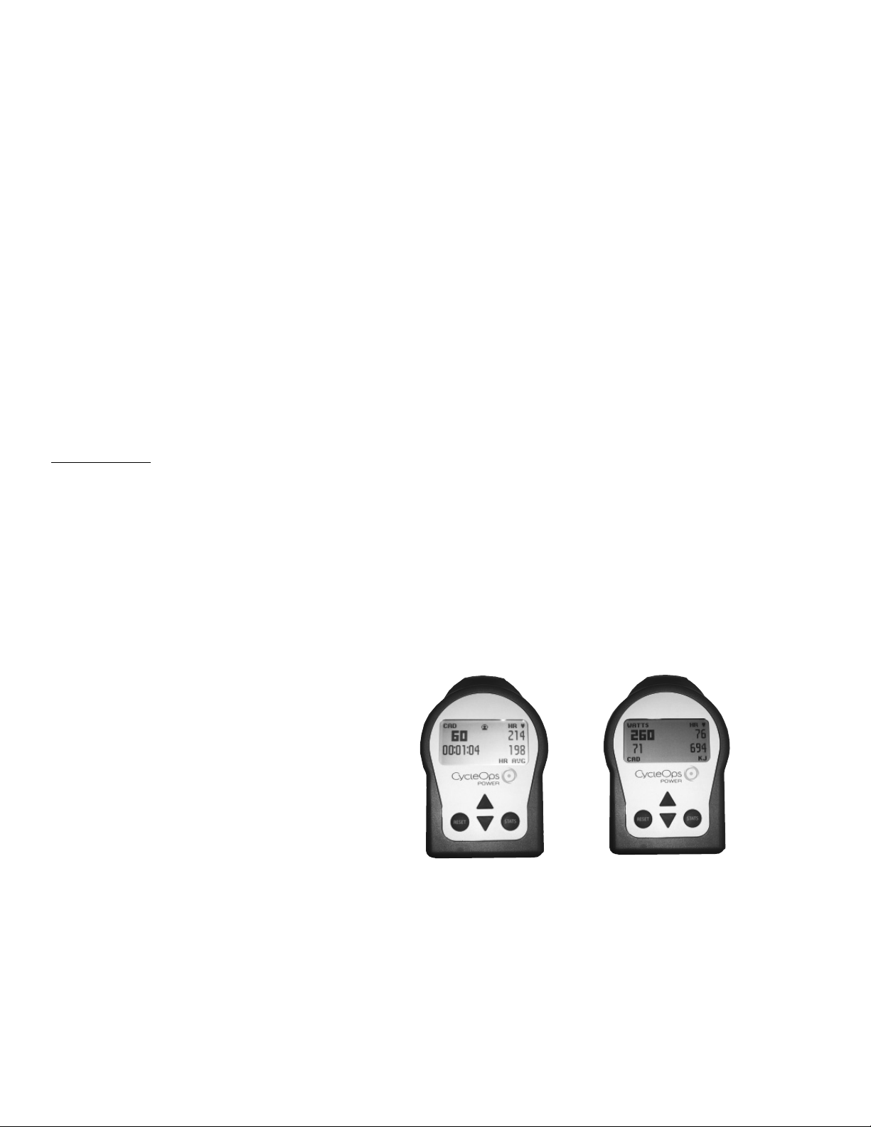
Comp 200E Pro 300PT
Console Display

10
STATS:Pressing and releasing the STATS button changes the screen from the dashboard display to the statistics display.
The statistics display shows max and average values for ride metrics as well as total elapsed ride time.When using
the USB stick (sold separately) pressing the STATS button again will show a third screen which displays elapsed
time in power zones.
Additional Console Functions:
By pressing and holding RESET and STATS simultaneously the console will enter Setup Mode.There are three options in setup
mode.These options are:
- Return to Ride - Selecting this line returns you to dashboard mode.
- Test - Selecting this option enters you into several test modes.Test modes should only be accessed when instructed by
Saris Cycling Group Technical Support Staff. For more information call 800-783-7257.
- Setup- This option allows you to access the setup features of the console. Only access this screen with the direction of
Saris Cyclilng Group technical support.
Setup (Time and Date)
Setup (Time & Date) 1
1) From [MAIN MENU] press
[DOWN ARROW] to scroll to
[SETUP] and press [STATS].
Setup (Time & Date) 2
2) Press [STATS] to enter [TIME
AND DATE].
Setup (Time & Date) 3
3) Press [STATS] and [DOWN ARROW] to toggle between a12 or 24 hour clock. Press [STATS]
to accept changes and reenter the scrolling menu.
4) Press [DOWN ARROW] to scroll to [TIME] and press [STATS].
5) Press [STATS] and [UP ARROW] or [DOWN ARROW] to enter time digits. Press [STATS]
to toggle through numbers. Press [STATS] to accept changes and reenter scrolling menu.
NOTE: Scroll through hour digits to select AM or PM times. The user is unable to modify the
metric of“seconds”time function.
6) Press [DOWN ARROW] to scroll to [DATE] and press [STATS].
7) Press [STATS] and [UP ARROW] or [DOWN ARROW] to enter date digits. Press [STATS] to
toggle through numbers. Press [STATS] to accept changes and reenter scrolling menu.
8) To begin a ride, press [DOWN ARROW] to scroll to [RETURN] and press [STATS]. Press the
[DOWN ARROW] to scroll to [RETURN] and press [STATS].
STATS
RESET STATS
RESET
STATS
RESET
Main Menu
Return to Ride
Test
ÎSetup
Main Menu
ÎTime and Date
Modes
Coded Sensor ID
Return
Time and Date
Î12-24 12
Time 11:04:13A
Date 04-13-07
Return

11
Setup Modes 1
1) From [MAIN MENU] press [DOWN ARROW] to scroll
to through to [SETUP] and press [STATS].
2) Press [STATS] to enter [MODES].
Setup Modes 2
3) Press [DOWN ARROW] to scroll to [COMP MODE] and press [STATS].
4) Press [DOWN ARROW] to toggle between [200E] or [PT300]. Select setting
depending CycleOps Indoor Cycle model you own.Press [STATS] to accept
changes and reenter scrolling menu.
5) Press [DOWN ARROW] to scroll to [RECORD CNTR] and press [STATS].
6) Press [DOWN ARROW] to toggle between [SPEED] and [HEART]. Press
[STATS] to accept changes and reenter scrolling menu.This function sets
when the ride time clock auto starts and stops. In [SPEED] mode, the run time
clock will stop when speed reaches zero.In [HEART] mode, the run time clock
time will continue to record as long as heart rate signal is detected.
7) Press [DOWN ARROW] twice to scroll to [BACKLIGHT] and press [STATS].
8) Press [DOWN ARROW] to select either [UI], [UI DATA] or [OFF].This function
determines when the backlight will be illuminated. [UI] = User Interface (when
buttons are pushed), [UI DATA] = User Interface and Data input, [OFF] =
Backlight is never illuminated. Press [STATS] to accept changes and reenter
scrolling menu.NOTE: Use of backlight will reduce battery life.
9) To reset user settings select press [DOWN ARROW] and press [STATS].
10) Press [DOWN ARROW] to scroll to [RETURN] and press [STATS] to return to
[MAIN MENU].
STATS
RESET
STATS
RESET
Main Menu
Time and Date
ÎModes
Coded Sensor ID
Return
Modes
ÎComp Mode PT300
Record Cntr Speed
Language English
Backlight UI Data
Reset
Return

12
Setup Coded Sensor ID 1
1) From [MAIN MENU] press [DOWN ARROW] to scroll
through and press [STATS].
2) Press [STATS] to enter [CODED SENSOR ID].
Note: Each console is coded to the hub of its Indoor Cycle. It is advised
that you note the HUB ID of each Indoor Cycle.When the batteries in the
hub are replaced you must relearn the HUB ID.
IMPORTANT: You can only execute the“LEARN”function on one Indoor
Cycle at a time. Make sure all other Indoor Cycles are asleep.To ensure
Indoor Cycles are asleep leave untouched for approximately 4 minutes.
Setup Coded Sensor ID 2
3) Press [STATS] to enter [HUB].
4) Press [STATS] to toggle through all digits until LEARN 1 is displayed.
5) Press and hold [STATS] until LEARN 1 flashes.
6) Once the console learns the Hub ID it will be displayed.
7) Press [DOWN ARROW] to scroll to [RETURN] and press [STATS] to return to
[MAIN MENU].
STATS
RESET
STATS
RESET
Main Menu
Time and Date
Modes
ÎCoded Sensor ID
Return
Coded Sensor ID
ÎHub LEARN 1
Stats 00000
Heart 00000
Reset
Return

13
Test Information (Current Firmware Version, LCD, Backlight, Hub Heart Wheel,Torque, Data Ride and Data Test)
These tests only need to be performed when instructed by customer support staff. For questions please contact Saris Cycling
Group at 1-800-783-7257 (001 608 274 6550 international).
CHAPTER 6: USB STICK:
The USB Stick is a very important part of the CycleOps Power Training System. The USB Stick is used to both capture ride
data as well as move it from the bike to a personal computer for detailed post-ride analysis via PowerAgent software. The
console still works without the Stick, but ride data will not be captured and only analog heart rate straps can be used to
monitor heart rate while riding. For more information on the USB Stick, visit www.cycleops.com.
CHAPTER 7: RF INTERFERENCE:
If during use you are experiencing wireless drop out this is due to frequency interference. Wireless Internet access points,
microwaves, cordless phones, or other wireless devices may cause frequency interference. To mitigate the chance of
interference set wireless access points to the lowest channel possible, and keep bikes away for interfering devices. To
change the channel on your access point, please consult your manufacturers documentation or your technology staff.
CHAPTER 8:
WARRANTY
Frame - 15 years
Parts - 3 years (excludes wear items)
Pedals - 90 days
Electronics - 1 year
Saris Cycling Group,Inc. warrants its PowerTap products against defects in manufacturing and workmanship for a period of one year, beginning at the date of purchase, or from the date
of manufacture in the absence of a proof of purchase.In the event of a warranty issue, Saris Cycling Group, Inc. will repair or replace the item at its discretion. Saris Cycling Group,Inc. is
not responsible for any indirect or consequential costs or damages associated with the warranty of the product. Our products are not covered under warranty in cases exhibiting signs of
abuse, improper maintenance or installation, crash, using the product with non-compatible components, or using the product for purposes for which it was not designed.This warranty is
also void if the product has been modified from its original form, including changes in aesthetics, serial numbers or logos. Saris Cycling Group Inc., is not responsible for basic hub main-
tenance,such as re-packing bearings and bearing adjustments. Warranty Procedures If it appears that a PowerTap component is not working properly, please take the time to inspect and
troubleshoot the system as best as possible.In many instances, solutions may be as simple as replacing a bearing or adjusting a sensor. Often small parts can repaired at the shop, instead
of the longer and more expensive option of sending the unit back for repair. If you feel the need to warranty your PowerTap, please return your product through the channel that you
purchased it from or contact Saris Cycling Group,Inc. at 1-800-783-7257.
Copyright
Copyright 2005. All rights reserved. No part of this publication may be copied,photographed, reproduced, translated, transmitted electronically or placed on digital media without the prior written consent of Saris
Cycling Group, Inc.
Trademarks
Saris Cycling Group, Inc ,PowerTap and the PowerTap logo, are all registered trademarks of Saris Cycling Group, Inc. All other product, brand,or trade names used in this manual may be trademarks or registered trade-
marks of their respective owners.
Modifications
Saris Cycling Group, Inc reserves the right to make improvements and/or updates to the products described herein at any time without notice.
FCC Statement of Compliance:
Statement of Compliance for FCC and Industry Canada:
“This device complies with Industry Canada and Part 15 of the FCC Rules. Operation is subject to the following two conditions:(1) This device may not cause harmful interference,and (2) this device must accept any
interference received, including interference that may cause undesired operation.”
The term “IC:”before the radio certification number only signifies that Industry Canada technical specifications were met.
Changes or modifications to this device not expressly approved by the party responsible for compliance with FCC regulations (the manufacturer) could void the user’s authority to operate the equipment.
This equipment has been tested and found to comply with the limits for a Class B digital device,pursuant to part 15 of the FCC Rules.These limits are designed to provide reasonable protection against harmful
interference in a normal installation.This equipment generates,uses and can radiate radio frequency energy and, if not installed and used in accordance with the instructions, may cause harmful interference to radio
communications. However, there is no guarantee that interference will not occur in a particular installation
Copyright 2007 Saris Cycling Group,Inc. 5253 Verona Road Madison, WI 53711 800-783-7257 17711 04/07
Table of contents
Other CycleOps Exercise Bike manuals

CycleOps
CycleOps Club Pro 300PT User manual

CycleOps
CycleOps PowerBeam Pro User manual

CycleOps
CycleOps FLUID2 User manual

CycleOps
CycleOps 100 PRO User manual

CycleOps
CycleOps Club Pro 300PT User manual

CycleOps
CycleOps JetFluid Pro User manual

CycleOps
CycleOps Club Pro 300PT User manual

CycleOps
CycleOps 400 Pro Series User manual

CycleOps
CycleOps Magnus User manual

CycleOps
CycleOps Hammer User manual