Cyclone Mobility RT300 User manual

August 1, 2018 Page 1 of 9
RT300 Supine Patient Setup Guide
This document provides setup instructions and troubleshooting strategies for the RT300 Supine

August 1, 2018 Page 2 of 9
1. Bike kit materials: Please have the following equipment before entering the patient’s room.
2 x pillowcase
1 x cotton bed sheet
1 x socks
1 x plastic bag
2. Lower bed side panels and remove the panel at the foot of the bed.
3. Adjust the bed so the patient’s torso is positioned at approximately a 45° incline (≥30° is
appropriate). Also ensure the patient is centered on the bed in supine.
4. Drape the bed sheet across the patient for privacy and gently move the patient’s legs so their feet
are at the sides of the bed.

August 1, 2018 Page 3 of 9
5. Move wires/lines into a safe position for cycling.
6. Pivot the lower hanger (located between the pedals and leg rests) into the cycling position.
7. Before moving the bike over the foot of the bed:
i. Connect the bike’s power cable to the nearest power source and turn the power switch on.
ii. Grab the handles with one person located on each side of the bike and pull/push to
lengthen/narrow the base to allow enough space to move the bike over the foot of the bed, if
needed.
iii. Adjust the height of the bike using the up/down switch to create enough clearance to safely
move the bike over the patient’s feet.
Storage/transport position
Cycling position

August 1, 2018 Page 4 of 9
8. Slide the bike over the foot of the bed until the patient’s heels are positioned beneath the metal
restraint devices.
9. Position the bike and patient for cycling.
i. The patient’s hips and shoulders should lie flat in the bed. The patient’s hips, shoulders and the
base of the bike should run parallel with one another.
ii. Imagine a straight line through the bike’s lower leg hanger to the head of the bed. Align the
bike through the centre-line of the patient with the body symmetrical on each side of the arm.

August 1, 2018 Page 5 of 9
10. Lock the two wheels that are positioned farthest from your patient.
11. Place the patient’s lower leg and foot onto the leg rest and pedal. Insert a rolled up pillowcase between the
leg and leg rest.
12. Fasten the straps over the foot to form an X and secure the lower leg into the calf support, then rotate the
pedals and repeat on the other side.
13. Assessing ROM and leg position:
Slowly guide the legs through the cycling movement and examine the following through the range of
motion (ROM):
i. No obvious discomfort
ii. Heels remain on the pedals and legs remain secured to lower-leg rests
iii. Lower-leg rests do not make contact with hamstrings
iv. Knee angle ranges from 90° in flexion to 160° in extension
v. Hip flexion is <90° throughout the movement

August 1, 2018 Page 6 of 9
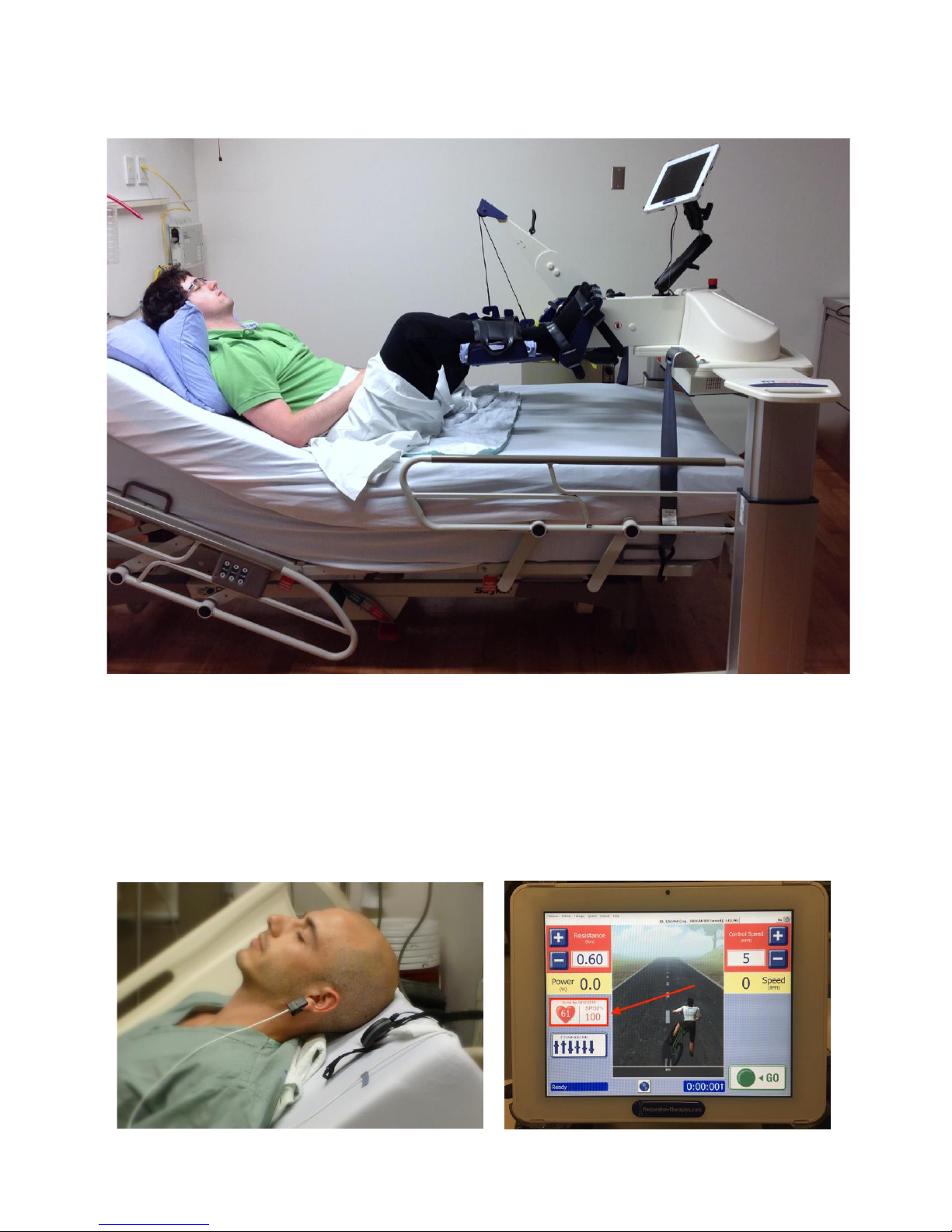
vi. Legs should have a maximum knee angle of 160° to prevent hyperextension with heels
remaining on pedal
vii. Lower leg should be parallel with the floor when it is in the 12 o’clock position (adjust the
height of the bike if necessary)
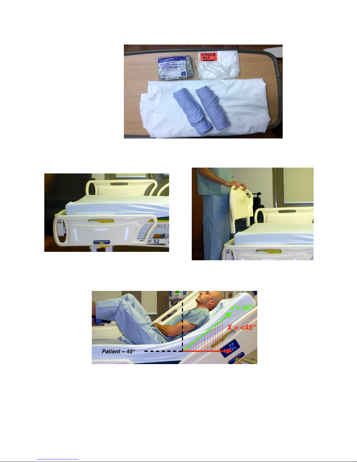
Guidelines for achieving proper patient positioning:
1. Excessive knee extension
Push the base of the bike towards the head of the bed/the patient
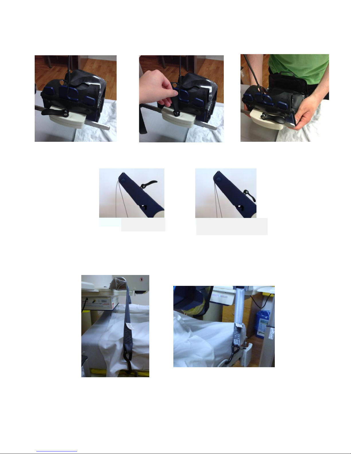
Tighten the Kevlar wires using the lock on the lower leg hander to straighten and secure the
legs into the lower leg rests
2. Excessive hip/knee flexion
Pull the bike towards the foot of the bed
3. Excessive knee abduction
Lengthen the lower leg rests
Push the bike towards the head of the bed/the patient
Tighten the Kevlar wires to straighten and secure the legs into the lower leg rests
4. Tibia/lower leg is not parallel with the floor in the 12 o’clock position
Raise/lower the bike’s elevation
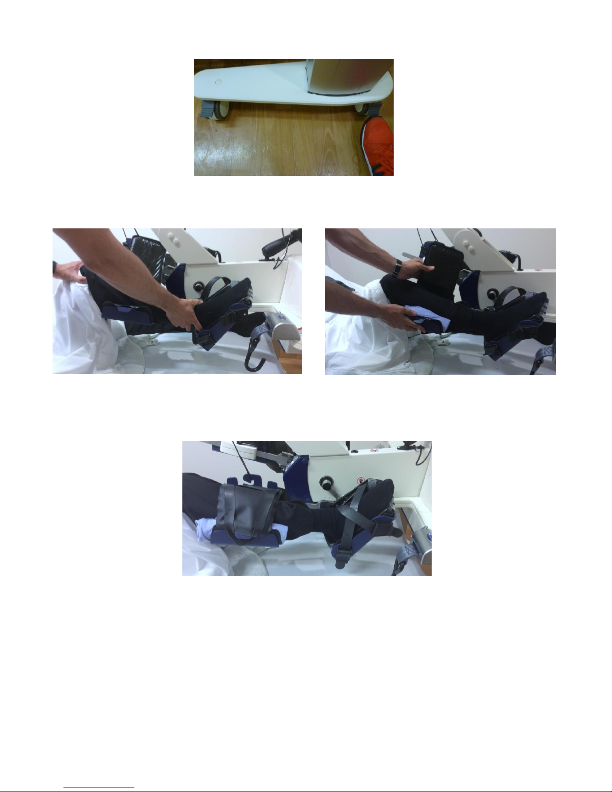
5. The lower leg rests are contacting the hamstrings
Shorten the lower leg rests
Knee ~ 160
3
3 o’clock
position
12
Knee ~ 135
12 o’clock
position
Lower Leg
Parallel with Floor

August 1, 2018 Page 7 of 9
14. Adjusting the length of the lower leg rests:
If knee extension, knee abduction and hip flexion are ideal but the lower leg rests continue to contact
the patient’s hamstrings throughout the ROM, adjust the position of the calf shells along the calf
support metal bar.
15. Remove slack in the Kevlar wires.
16. Secure the bike to the bed.
i. Lock all 4 wheels
ii. Secure and tighten both metal safety-belt hooks to an immobile part of the bed and use the red
lever and triangle dial on the metal restraints to fasten the hook tight to the bed
Slack
Slack taken up

August 1, 2018 Page 8 of 9
17. Final setup:
18. Attach the SpO2sensor to the patient’s earlobe.
i. Turn on the SAGE controller by pressing the small power button on the left side.
ii. Check that the pulse oximeter is powered on and there is adequate battery to complete the
session.
iii. Observe HR and SPO2data on the bike’s tablet before proceeding.
iv. Upon session completion, ensure nothing is lodged between the sensor before storing and
check that the device is powered off.

August 1, 2018 Page 9 of 9
19. Initiate therapy:
i. Log in: tap “Clinician” on the toolbar then select “Clinician Login” from the dropdown menu.
Use code 1776 and tap OK.
ii. Tap “Patient” on the toolbar then “Open Patient” on the dropdown menu. Enter the patient ID
and PIN to login.
iii. Ensure that SpO2and heart rate are registering on the screen.
iv. Press GO and continue to assess the patient’s positioning and response as needed.
For help, please contact RTI: 800-609-9166 ext. 343