CYP CDPS-4KQ User manual

CDPS-4KQ
1 by 4 HDMI 4K UHD TV Wall Splitter
Operation Manual
Operation Manual


DISCLAIMERS
The information in this manual has been carefully checked and
is believed to be accurate. Cypress Technology assumes no
responsibility for any infringements of patents or other rights of third
parties which may result from its use.
Cypress Technology assumes no responsibility for any inaccuracies
that may be contained in this document. Cypress also makes no
commitment to update or to keep current the information contained
in this document.
Cypress Technology reserves the right to make improvements to this
document and/or product at any time and without notice.
COPYRIGHT NOTICE
No part of this document may be reproduced, transmitted,
transcribed, stored in a retrieval system, or any of its part translated
into any language or computer le, in any form or by any means—
electronic, mechanical, magnetic, optical, chemical, manual, or
otherwise—without express written permission and consent from
Cypress Technology.
© Copyright 2011 by Cypress Technology.
All Rights Reserved.
Version 1.1 August 2011
TRADEMARK ACKNOWLEDGMENTS
All products or service names mentioned in this document may be
trademarks of the companies with which they are associated.

SAFETY PRECAUTIONS
Please read all instructions before attempting to unpack, install or
operate this equipment and before connecting the power supply.
Please keep the following in mind as you unpack and install this
equipment:
• Always follow basic safety precautions to reduce the risk of re,
electrical shock and injury to persons.
• To prevent re or shock hazard, do not expose the unit to rain,
moisture or install this product near water.
• Never spill liquid of any kind on or into this product.
• Never push an object of any kind into this product through any
openings or empty slots in the unit, as you may damage parts
inside the unit.
• Do not attach the power supply cabling to building surfaces.
• Use only the supplied power supply unit (PSU). Do not use the PSU
if it is damaged.
• Do not allow anything to rest on the power cabling or allow any
weight to be placed upon it or any person to walk on it.
• To protect the unit from overheating, do not block any vents or
openings in the unit housing that provide ventilation and allow for
sufcient space for air to circulate around the unit.
REVISION HISTORY
VERSION NO. DATE (DD/MM/YY) SUMMARY OF CHANGE
VR0 07/08/15 Preliminary Release

CONTENTS
1. Introduction............................................ 1
2. Applications........................................... 1
3. Package Contents ................................ 1
4. System Requirements............................ 1
5. Features.................................................. 2
6. Operation Controls and Functions....... 2
6.1 Front Panel ........................................2
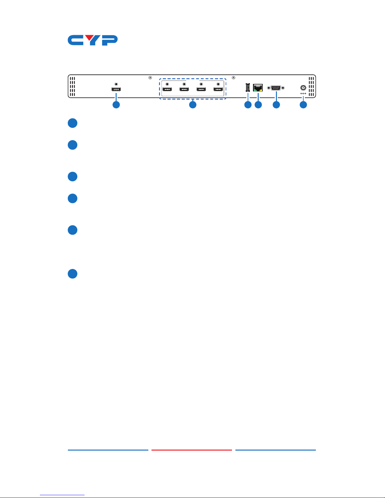
6.2 Rear Panel.........................................3
6.3 RS-232 Protocols ...............................5
6.4 RS-232 and Telnet Commands .......6
6.5 Telnet Control .................................12
6.6 PC Application Control .................14
6.6.1 System Settings......................15
6.6.2 Connect Interface................16
6.6.3 Network Conguration.........16
6.6.4 TV Wall Setup (1) ...................17
6.6.5 TV Wall Setup (2) ...................18
6.6.6 TV Wall Setup (3) ...................19
6.6.7 I/O Setup................................20
6.6.8 Image Adjust .........................21
7. Connection Diagram .......................... 22
8. Specications ...................................... 24
8.1 Technical Specications ...............24
8.2 Supported Resolutions...................25
8.3 Output Resolution Limitations .......26
9. Acronyms ............................................. 29

1
1. INTRODUCTION
The 1 by 4 UHD TV Wall allows an HDMI 4K2K input source to be freely
arranged on 4 displays (TV or monitor) with bezel correction function.
Friendly control application that leads and leave the TV Wall control
system never been easier. The device supports video output timings
up to WUXGA@60RB and 1080p@60Hz, audio format up to 7.1CH
LPCM at 192kHz sampling rate based on input source EDID. All the
operation and control can be done through Telnet and RS-232.
2. APPLICATIONS
• Public Advertisement
• Digital Presentation
• Hypermarket Display
• Stock Market
3. PACKAGE CONTENTS
• 1×1 by 4 HDMI 4K UHD TV Wall Splitter
• 1×12 V/3 A DC Power Adaptor
• 1×Operation Manual
4. SYSTEM REQUIREMENTS
Input Source such as DVD/Blu-ray players or any HDMI signal and
output HD TV/displays.

2
5. FEATURES
• HDMI with 4K2K supported, HDCP and DVI compliant
• Output source signal to 4 displays as a full image with adjustable
Bezel Correction
• Input PC resolutions support from VGA~WUXGA and HDTV from
480i~1080p and 4K2K@24/25/30Hz
• Supports different input resolutions and output resolutions selectable
from TV wall application
• Supports AC3/DTS/Dolby Digital Plus/Dolby TrueHD/Dolby Atmos
and DTS-HD Master Audio
• Supports RS-232 and Telnet controls
6. OPERATION CONTROLS AND FUNCTIONS
6.1 Front Panel
4K UHD
POWERPOWER
1X4 UHD TV WALL CDPS-4KQ
1
1
POWER: Press POWER button to power on the unit or set to standby
mode.
When power is disconnected, presses this button and connected
the power to reset the system back to default factory setting.
When power is on, long press this button for 3 seconds, output
monitor will show “USB Host Update MCU Firmware Start…”, then
plug USB (with Firmware upgrade bin le contained) to upgrade
automatically. If monitor shows “Mass Storage Host Upgrade
Running” it means that the upgrade is proceeding, after upgrade
nished, the unit will reboot.
Note: If monitor didn’t show “Mass Storage Host Upgrade Running”,
means rmware upgrade didn’t success, please power off the unit
and try again.

3
6.2 Rear Panel
HDMI OUTHDMI IN
D1CBA
CONTROLSERVICE RS-232 DC 12V
1 2 3 4 5 6
1
HDMI IN: Connect with HDMI source equipment such as DVD/Blue-
ray players and or PC/Laptop devices.
2
HDMI OUT A~D: Connect with HDMI TV/displays for output image
display. It is suggest that the connection sequence should be
placed as diagram showed below for TV wall set up.
3
SERVICE: This slot is for rmware update use only, work in
accordantly with Power button.
4
CONTROL: Connect to an active network for telnet control.
Collocated with “CDPS-4KQ AP” application could do multi-device
control.
5
RS-232: Connect from PC/Laptop with D-Sub 9pin cables for RS-232
command sending and controlling over the device.
Note: RS-232 control system is limited to a single Video Wall unit.
Whereas Telnet can control multi-Video Wall unit.
6
DC 12V: Plug 12V DC power supply which included in the package
into the unit then connect the adaptor to an AC outlet.

4
Source
HDMI IN
RS-232
HDMI OUT
2x2 Wall
(4xDisplays)
A B
DC
D C B A
PC/
RS-232
Control
Device
3x2 Wall
(6xDisplays)
Source
HDMI IN
Control
HDMI OUT
A B
ED
C
F
D C B A
HDMI IN
Control
HDMI OUT
H G F E
PC
Router
Splitter
3x3 Wall
(9xDisplays)
HDMI IN
Control
HDMI OUT
A B C
ED F
HG I
D C B A
HDMI IN
Control
HDMI OUT
HDMI IN
Control
HDMI OUT
L K J I
H G F E
Source
Splitter
PC
Router

5
6.3 RS-232 Protocols
HDMI SPLITTER
►
◄
REMOTE CONTROL (PC)
Pin Denition Pin Denition
1NC 1 NC
2TxD 2RxD
3RxD 3TxD
4 NC 4 NC
5 GND 5 GND
6 NC 6 NC
7 NC 7 NC
8 NC 8 NC
9 NC 9 NC
Baud Rate: 115200bps
Data Bit: 8 bits
Parity: None
Flow Control: None
Stop Bit: 1

6
6.4 RS-232 and Telnet Commands
COMMAND DESCRIPTION PARAMETER
HELP(?) Show Command list NONE
HELP(?) N Show Command
description
N=Command name
RRES Request Current Output
Resolution
NONE
SRES N1 Set Output Resolution to
N1
N1=0(640x480@60),
1(480p60), 2(576p50),
3(800x600@60),
4(848x480@60),
5(1024x768@60),
6(720p50), 7(720p60),
8(1280x768@60),
9(1280x800@60),
10(1280x960@60),
11(1280x1024@60),
12(1360x768@60),
13(1366x768@60),
14(1400x1050@60),
15(1440x900@60),
16(1600x900RB@60),
17(1600x1200@60),
18(1680x1050@60),
19(1080p50), 20(1080p60),
21(1920x1200RB@60),
22(2048x1152RB@60),
23(1080I50), 24(1080I60),
25(1080p24), 26(1080p25),
27(1080p30), 28(Native)

7
COMMAND DESCRIPTION PARAMETER
RINS Get Input Resolution 0(VGA60), 1(VGA72),
2(VGA75), 3(VGA85),
4(WXGA60), 5(WXGA75),
6(XGA60), 7(XGA70),
8(XGA75), 9(XGA85),
10(SXGA60), 11(SXGA75),
12(SVGA56), 13(SVGA60),
14(SVGA72), 15(SVGA75),
16(SVGA85),
17(DTV_480P60),
18(DTV_576P50),
19(DTV_480I60),
20(DTV_576I50),
21(HDTV_720P50),
22(HDTV_720P60),
23(HDTV_1080I50),
24(HDTV_1080I60),
25(HDTV_1080P24),
26(HDTV_1080P50),
27(HDTV_1080P60),
28(V848_480_60),
29(V852_480_60),
30(V854_480_60),
31(V1024_852_60),
32(V1024_1024_60),
33(V1280_800_60),
34(V1280_960_60),
35(V1360_768_60),
36(V1366_768_60),
37(V1440_900_60),
38(V1400_1050_60),
39(V1360_1024_60),
40(V1600_900_60),
41(V1600_1200_60),
42(V1680_1050_60),
43(V1920_1200_60),
44(V2048_1080_24_1),
45(V2048_1080_24_2),

8
COMMAND DESCRIPTION PARAMETER
46(V2048_1080_60),
47(V2048_1152_1),
48(V2048_1152_2),
49(V2048_1152_3),
50(V3840_2160_24),
51(V3840_2160_25),
52(V3840_2160_30),
53(V4096_2160_24), 54(K_
NO_SIGNAL), 55(K_NO_
SUPPORT)
ROSDD Request Current OSD
Display State
NONE
SOSDD N1 Set OSD Display Enable/
Disable
N1=0(OFF), 1(ON)
ROSDH Request Current OSD
Horizontal Position
NONE
SOSDH N1 Set OSD Horizontal Position
to N1
N1=0~20 (5)
ROSDV Request Current OSD
Vertical Position
NONE
SOSDV N1 Set OSD Vertical Position
to N1
N1=0~20 (5)
ROSDT Request OSD Display
Current Timeout Setting
NONE
SOSDT N1 Set OSD Display Timeout
Setting
N1=0(Off), 5~50 (50)
ROSDG Request OSD Gain
Correction
NONE
SOSDG N1 Set OSD Gain Value N1=0~10 (2)
SOSDI Show OSD Information
On/Off
NONE
SOSDR Reset All OSD Settings NONE
RBRI N1 Request Channel N1
Brightness Value
N1= 1~4

9
COMMAND DESCRIPTION PARAMETER
SBRI N1 N2 Set Channel N1 Brightness
Value to N2
N1= 1~4, N2=0~100(50)
RCON N1 Request Chanel N1
Contrast Value
N1=1~4
SCON N1 N2 Set Channel N1 Contrast
Value to N2
N1= 1~4, N2=0~100(50)
RSAT Request Current
Saturation Value
NONE
RSAT N1 Request Channel N1
Current Saturation Value
N1=1~4
SSAT N1 N2 Set Channel N1 Saturation
Value to N2
N1= 1~4, N2=0~100(50)
RHUE N1 Request Channel N1
Current Hue Value
N1=1~4
SHUE N1 N2 Set Channel N1 Hue Value
to N2
N1= 1~4, N2=0~100 (50)
SIMRE N1 Reset Brightness/Contrast/
Saturation/Hue Value to
Default
N1=1(Brightness),
2(Contrast), 3(Saturation),
4(Hue)
SPIRE Reset all Channels
Brightness, Contrast,
Saturation, Hue Value to
Default
NONE
RIPM Request Current IP Mode NONE
SIPM N1 Set IP Mode to DHCP or
Static
N1=0(Static), 1(DHCP)
(192.168.1.50)
RIPA Request Current Static IP
Address to Screen
NONE
SIPA X.X.X.X Set Static IP Address X=0~255 (192.168.1.50)
RMAA Request Current Static
Subnet Address
NONE
SMAA X.X.X.X Set Static Subnet Address X=0~255 (255.255.255.0)

10
COMMAND DESCRIPTION PARAMETER
RGAA Request Current Static
Gateway Address
NONE
SGAA X.X.X.X Set Static Gateway
Address
X=0~255 (192.168.1.50)
RETIME Request Current Ethernet
Timeout
NONE
SETIME N1 Set Ethernet Timeout N1=0(OFF), 1(10 Minutes),
2(20 Minutes), 3(30
Minutes), 4(40 Minutes),
5(50 Minutes), 6(60
Minutes)
RLINK Request Ethernet Address NONE
RMUTE Request Current Mute NONE
SMUTE N1 Set Mute Audio N1=0(Unmute), 1(Mute)
RPOW Request Current Power
State
NONE
SPOW N1 Set the Unit Power On/Off N1=0(Off), 1(On)
RVER Request Version NONE
SREL Relink the Unit in 2
Seconds
NONE
SDEF Reset the Unit to Factory
Defaults
NONE
RMN Request Current TV Wall
Format
NONE
SMN N1 N2 Set TV Wall N1 Row and
N2 Column
N1=1~15(Row),
N2=1~15(Column)
RBH Request TV Wall Horizontal
Bezel Correction
NONE
SBH N1 Set TV Wall Horizontal
Bezel Correction
N1=0~255
RBV Request TV Wall Vertical
Bezel Correction
NONE

11
COMMAND DESCRIPTION PARAMETER
SBV N1 Set TV Wall Vertical Bezel
Correction
N1=0~255
RBEZ Request Current Bezel
Correction State
NONE
SBEZ N1 Set Bezel Correction
Enable/Disable
N1=0(Off), 1(On)
RMDN Request Unit ID Number NONE
SMDN N1 Set Unit ID Number to N1 N1=0~255
SWDE Reset All TV Wall Settings NONE
SHOT N1 Fast Setting TV Wall Format
from Hotkey N1
N1=0(1x1), 1(2x2), 2(3x3),
3(4x4), 4(5x5), 5(6x6),
6(2x3), 7(3x2), 8(3x4),
9(4x2), 10(4x3), 11(4x5),
12(1x2), 13(2x1), 14(1x3),
15(3x1), 16(1x4), 17(4x1),
18(2x4), 19(3x5), 20(5x4),
21(5x3), 22(6x2), 23(6x3)
SFAVE N1 Save Current TV Wall
Settings to N1
N1=1~5
RFAVE N1 Recall TV Wall Settings
from N1
N1=1~5
Note:
1. All the RS-232 command will be not executed unless followed with
a carriage return. All commands are insensitive.
2. RS-232 control is set to single device only, not for use with
Cascade/Bypass output's connection device.
3. Bold values are the default settings.

12
6.5 Telnet Control
To access the Telnet control in Windows 7, click on the ‘Start’ menu
and type “cmd” in the Search eld then press Enter. Under Windows
XP go to the ‘Start’ menu and click on “Run”, type “cmd” with then
press Enter.
Under Mac OS X, go to Go→Applications→Utilities→Terminal. See
below for reference.
Once in the command line interface (CLI) type 'telnet', then the IP
address of the unit(default is 192.168.1.50) and hit Enter. If the Telnet
port (unit's port) is not set to the default of "23" then the correct port
number will need to be entered after the IP address as shown below.

13
This will bring us into the unit which we wish to control. Type 'HELP' to list
the available commands.
Note:
1. All the commands will be not executed unless followed by a
carriage return. Commands are case-insensitive.
2. If the IP is changed then the IP Address required for Telnet access
will also change accordingly.

14
6.6 PC Application Control
Use the link http://cypress.com.tw to download the software
application of 1 By 4 HDMI 4K UHD Video Wall Splitter and execute it
to control the Video Wall system.
Note: Before installing, remove any former verion that was existing.
Once the application is installed successfully, click and open the
“Video Wall Set”.
1
1
Search MAC: Click on “Search MAC” to conrm how many TV Wall
unit(s) is within the network system then, select from here with the
unit you wish to control.
Note: This action should be executed every time when the unit is
power On or reset or re-run the “CDPS-4KQ AP” application.
Select the unit that is to be adjusted then pressed “Connect” to
connecting the unit.
Every time when the unit is connected successfully, a dialog will
appear showing “refresh completed” base on the selected MAC
and the application will display current unit’s status. However,
image display will not be refreshed automatically and can only be
refreshed manually.
When using more than 1 unit for a TV Wall setting, set up unit’s ID
number is required to ensure the correct display of each single TV
wall image.

15
6.6.1 System Settings
1
2
3
4
1
Power: Click on “Power” to power on/off the controlled unit. To
control all connected units, click on “ALL IP” then click Power. From
power ON to power OFF the application will disconnect the link, to
power ON again please re-Connect.
2
Factory Reset: Click on “Factory Reset” to set device settings to
default, to switch all devices back to default setting click ALL IP
and then“Factory Reset”.
3
Refresh: Click on “Refresh” to read device current settings, all
status of TV Wall Set will follow current choose device.
Note: Image Adjust will not be refreshing, users have to click on
“Image Adjust” to manually refresh to read Image Adjust current
status.
4
Search MAC: Click on “Search MAC” to dene on-line TV Wall
units.
Table of contents
Other CYP Cables And Connectors manuals