CYP CH-1529TXPL User manual
Operation Manual
Operation Manual
CH-1529TXPL/RXPL
HDCP 2.2 & HDMI2.0 Extender with OAR / Audio
Insertion


DISCLAIMERS
The information in this manual has been carefully checked and
is believed to be accurate. Cypress Technology assumes no
responsibility for any infringements of patents or other rights of third
parties which may result from its use.
Cypress Technology assumes no responsibility for any inaccuracies
that may be contained in this document. Cypress also makes no
commitment to update or to keep current the information contained
in this document.
Cypress Technology reserves the right to make improvements to this
document and/or product at any time and without notice.
COPYRIGHT NOTICE
No part of this document may be reproduced, transmitted,
transcribed, stored in a retrieval system, or any of its part translated
into any language or computer le, in any form or by any means—
electronic, mechanical, magnetic, optical, chemical, manual, or
otherwise—without express written permission and consent from
Cypress Technology.
© Copyright 2012 by Cypress Technology.
All Rights Reserved.
Version 1.0 Dec 2015
TRADEMARK ACKNOWLEDGMENTS
All products or service names mentioned in this document may be
trademarks of the companies with which they are associated.

SAFETY PRECAUTIONS
Please read all instructions before attempting to unpack, install or
operate this equipment and before connecting the power supply.
Please keep the following in mind as you unpack and install this
equipment:
• Always follow basic safety precautions to reduce the risk of re,
electrical shock and injury to persons.
• To prevent re or shock hazard, do not expose the unit to rain,
moisture or install this product near water.
• Never spill liquid of any kind on or into this product.
• Never push an object of any kind into this product through any
openings or empty slots in the unit, as you may damage parts
inside the unit.
• Do not attach the power supply cabling to building surfaces.
• Use only the supplied power supply unit (PSU). Do not use the PSU
if it is damaged.
• Do not allow anything to rest on the power cabling or allow any
weight to be placed upon it or any person walk on it.
• To protect the unit from overheating, do not block any vents or
openings in the unit housing that provide ventilation and allow for
sufcient space for air to circulate around the unit.
REVISION HISTORY
VERSION NO. DATE DD/MM/YY SUMMARY OF CHANGE
RDV1 08/03/16 Preliminary Release

CONTENTS
1. Introduction..................................................1
2. Applications.................................................1
3. Package Contents ......................................1
4. System Requirements..................................2
5. Features........................................................2
6. Operation Controls and Functions.............3
6.1 Front Panel of Transmitter..................... 3
6.2 Rear Panel of Transmitter ..................... 4
6.3 Right Side Panel of Transmitter ............ 4
6.4 Front Panel of Receiver ...................... 10
6.5 Rear Panel of Receiver ...................... 11
6.6 IR Cable Pin Assignment..................... 11
6.7 D-Sub 9 Pin Denitions ........................ 12
7. Specications ............................................13
7.1 CAT5e/6/7 Cable Specication ........ 15
7.2 Timing Support Table .......................... 15
7.3 HDBT Features ..................................... 16
8. Connection and Installation.....................17
9. Acronyms ...................................................18

1
1. INTRODUCTION
The HDMI over single CAT5e/6/7 Transmitter and Receiver set is a
great solution to extend uncompressed audio/video and IP data
over a single run of CAT5e/6/7 cable at a distance up to 60 meter.
Multi-control interfaces are available which includes IR, RS-232 and
USB connection. This new extender set complies with advanced
protocols of HDCP2.2 and HDMI 2.0, the HDCP1.4 also supported.
The 6G HDMI video is able to be processed. Except extend 4K2K
data, it features useful audio functions. The “optical audio return”
supports audio transmit back from Receiver to Transmitter. Besides,
the “audio insertion” allows external audio insert to HDMI video such
as background music insertion. The HDBT clock stretch and TMDS re-
clocking are considered. The Receiver (PD) can be powered by the
PoE 48V function of the Transmitter (PSE), allowing for greater exibility
to t different installation scenarios.
2. APPLICATIONS
• 48V PoE from Transmitter (PSE) to Receiver (PD)
• Household entertainment sharing and control
• Lecture room display and control
• Showroom display and control
• Meeting room presentation and control
• Classroom display and control
3. PACKAGE CONTENTS
• 1 x HDMI over CAT5e/6/7 Transmitter
• 1 x HDMI over CAT5e/6/7 Receiver
• 1 x IR Blaster
• 1 x IR Extender
• 1 x 48V / 0.83A DC power adapter
• 1 x Power cable
• 2 x RS232 terminal block pitch
• 2 x Audio terminal block
• 2 x Rack ear Sets
• 1 x Operation Manual

2
4. SYSTEM REQUIREMENTS
Input source equipment such as PS3/Blu-ray player and output HD TV/
display.
5. FEATURES
• HDCP 1.4/HDCP 2.2 and HDMI 2.0 compliant
• HDMI with 3D, 4K2K support and DVI Compliant
• 6G HDMI video (3840x2160 YUV444) input is supported
• Simultaneous transmission of uncompressed data over a single
CAT5e/6/7 cable up to 60m /196.8 ft at 1080p and 35m/115ft at 4K2K
• 4Play™ convergence: HDMI, PoE & Control (IR & RS-232)
• Supports output resolution up to 4K2K@50/60 _YUV_420
• Supports deep color input and output of 8 bits, 10 bits and 12 bits
• Supports CEC bypass
• Optical audio return supports audio transmit back from receiver to
transmitter
• Audio insertion supports external audio insert to HDMI video such as
background music insertion
• Supports EDID management PC software with default EDID and
native EDID from display or other sink devices
• Supports HDMI DDC bus clock stretch for better compatibility of some
Blu-ray players
• Manages TMDS re-clocking and signal re-generation for better signal
• Supports standard 48V from Transmitter (PSE) to Receiver (PD)
• Easily rmware update via USB in eld
• Ultra-thin wall plate design with friendly installation (The thickness is
16mm only)
Note: 1. The standard 48V PoE function is designed for powering
compatible Receiver units only---non-PoE Receivers will need
their own power supply. Receivers of another brand may not
be compatible.
2. Displaying HDMI 3D and 4K2K contents, equivalent source
signal and HDMI cable are required in order to secure the
quality.

3
6. OPERATION CONTROLS AND FUNCTIONS
6.1 Front Panel of Transmitter
DC 48V
POWER
OPT. OUTIR IN 2IR OUT 1SERVICERS-232
TX RX
+
-
AUDIO OUT
UPDATE
LR
1 2 3 65 7 8 94
1DC 48V: Plug the 48V DC power supply into the unit. Please do
follow the label on adapter to connect the black cable to ground
pin of connector.
2Power LED: This LED will illuminate once the device is connected to
a power supply.
3Audio out: Connects to speaker with RCA input for audio signal
output.
4OPT. out: The optical out is for receiving optical audio from
Receiver then transmits to other connected devices such as
speakers.
5IR Out 1: IR Out 1 is considered as IR extender which to connect
to the supplied IR Extender cables for IR signal reception. Ensure
that remote being used is within the direct line-of-sight of the IR
Extender.
6IR In 2: IR In 2 is considered as IR BLASTER which connects to the
supplied IR Blaster cable for IR signal transmission. Place the IR
Blaster in direct line-of-sight of the equipment to
7SERVICE: This service slot is USB2.0 which is for rmware update
purpose.
8RS-232: Connect to a PC or Laptop via RS232 terminal to D-Sub 9-pin
cable for the transmission of RS-232 commands.
9Update: When update the rmware, the switch shall arrange to left
side (just follow arrow direction on case) and arrange back when
completing update.
4
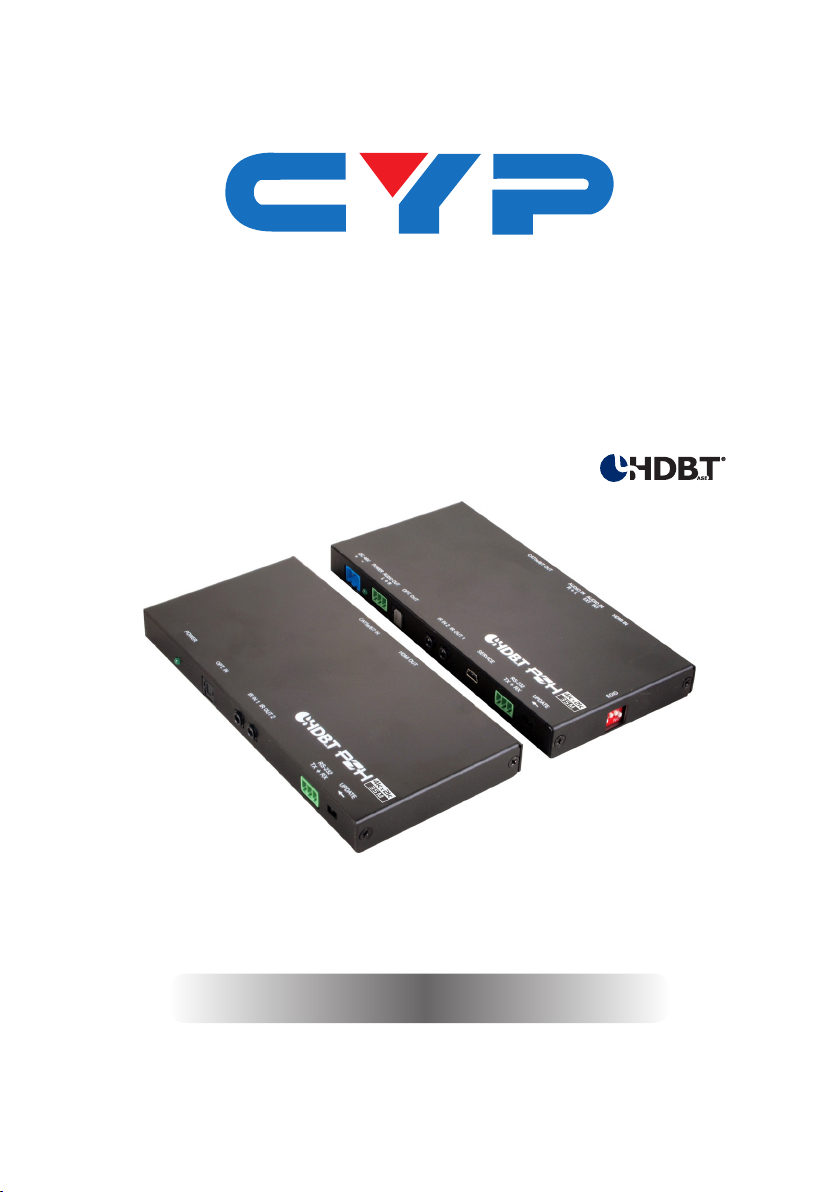
6.2 Rear Panel of Transmitter
AUDIO IN AUDIO IN HDMI INCAT5e/6/7 OUT
RL
EXT INT
1 2 3 4
1CAT5e/6/7 Out: Connects to the Receiver unit with a single
CAT5e/6/7 cable for transmission of all data signals includes power.
2Audio In: This phoenix connector allowing connect to analog
audio devices such as DVD players.
3Audio In Ext / Int: The slide switch provides customer to select
external audio which means insert external audio to displayed
video. Please slide the switch to EXT for external audio insertion.
The slide switch at “INT” means audio remain current HDMI one.
4HDMI IN: Connects to HDMI source equipment such as a DVD or
Blu-ray player.
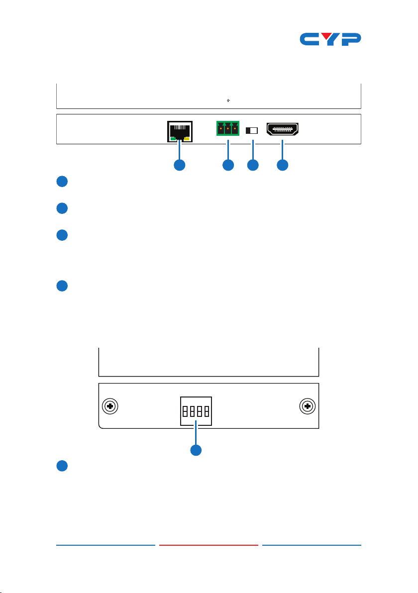
6.3 Right Side Panel of Transmitter
EDID
1
ON
1234
1EDID: EDID switch offers EDID selection. There are 16 sets of EDID
selection totally which divide to three modes includes “internal
mode”, “user mode” and “native mode”. 6 set of internal EDID,
9 sets are dened as user mode which are allowing customer to
upload as prefer one. The last one is native EDID which copies EDID
from sink device.

5
Dipswitch Selection for EDID:
Mode Number Dipswitch Number
Internal Mode 1 0000
2 1000
3 0100
4 1100
5 0010
6 1010
User Mode 7 0110
8 1110
9 0001
10 1001
11 0101
12 1101
13 0011
14 1011
15 0111
Native Mode 16 1111
EDID Detail Information:
1) Internal Mode:
1. Internal Mode FHD / 2 channel: 1080p/60 148M, No deep color
8bits, 2Ch
1. FHD / 2 channel: 1080p/60 148M, No deep color 8bits, 2Ch
2. FHD/ Multi channel: 1080p/60 148M, No deep color 8bits, 8Ch
3. UHD / 2 channel: 3840 x 2160p/30Hz 297M, No deep color 8bits, 2Ch
4. UHD / Multi channel: 3840 x 2160p/30Hz 297M, No deep color 8bits
, 8Ch
5. UHD+ / 2 channel: 3840 x 2160p/60Hz 594M, deep color 12bits, 2Ch
6.UHD+ / Multi channel: 3840 x 2160p/60Hz 594M, deep color 12bits, 8Ch
2) User Mode:
7~15. User Mode Upload mode. Default: FHD / 2 channel: 1080p/60
148M, No deep color 8bits, 2Ch
3) Native mode:
16. Copy EDID from sink device
This manual suits for next models
1
Table of contents
Other CYP Extender manuals

CYP
CYP PU-IR01 User manual

CYP
CYP CH-506TXL Instruction Manual

CYP
CYP CH-1109TX User manual

CYP
CYP PU-USB-KIT User manual

CYP
CYP Suprex SPX-7400 Series User manual

CYP
CYP PU-514L-KIT User manual

CYP
CYP PUV-1510RX User manual

CYP
CYP CH-1109TX User manual

CYP
CYP CH-506TX User manual

CYP
CYP PU-513L-KIT User manual


