CYP PU-506-KIT User manual

PU-506-KIT
3-Play HDBaseT™ Extender Kit (2-way IR, RS-232 & HDMI,
up to 100m)
OPERATION MANUAL


3
DISCLAIMERS
The information in this manual has been carefully checked and is
believed to be accurate. CYP (UK) Ltd assumes no responsibility for any
infringements of patents or other rights of third parties which may result
from its use.
CYP (UK) Ltd assumes no responsibility for any inaccuracies that may be
contained in this document. CYP (UK) Ltd also makes no commitment to
update or to keep current the information contained in this document.
CYP (UK) Ltd reserves the right to make improvements to this document
and/or product at any time and without notice.
COPYRIGHT NOTICE
No part of this document may be reproduced, transmitted, transcribed,
stored in a retrieval system, or any of its part translated into any language
or computer le, in any form or by any means—electronic, mechanical,
magnetic, optical, chemical, manual, or otherwise—without express
written permission and consent from CYP (UK) Ltd.
© Copyright 2020 by CYP (UK) Ltd.
All Rights Reserved.
Version 1.1
TRADEMARK ACKNOWLEDGMENTS
All products or service names mentioned in this document may be
trademarks of the companies with which they are associated.

4
SAFETY PRECAUTIONS
Please read all instructions before attempting to unpack, install or operate
this equipment and before connecting the power supply.
Please keep the following in mind as you unpack and install this
equipment:
• Always follow basic safety precautions to reduce the risk of re,
electrical shock and injury to persons.
• To prevent re or shock hazard, do not expose the unit to rain,
moisture or install this product near water.
• Never spill liquid of any kind on or into this product.
• Never push an object of any kind into this product through any
openings or empty slots in the unit, as you may damage parts inside
the unit.
• Do not attach the power supply cabling to building surfaces.
• Use only the supplied power supply unit (PSU). Do not use the PSU if
it is damaged.
• Do not allow anything to rest on the power cabling or allow any
weight to be placed upon it or any person walk on it.
• To protect the unit from overheating, do not block any vents or
openings in the unit housing that provide ventilation and allow for
sucient space for air to circulate around the unit.
REVISION HISTORY
VERSION NO. DATE SUMMARY OF CHANGE
v1.01 08/10/2013 First release
v1.02 19/08/2019 Updated Specications
v1.03 26/02/2020 Corrected the video bandwidth -
Technical Specications

5
CONTENTS
1. Introduction...........................................6
2. Applications ...........................................6
3. Package Contents ..................................6
4. System Requirements ...........................7
5. Features..................................................7
6. Operation Controls and Functions.......8
6.1 Transmitter Front and Rear Panels....... 8
6.2 Receiver Front and Rear Panels ............ 9
6.3 D-Sub 9-Pin Denitions.........................10
6.4 IR Cable Pin Assignment .......................10
7. Connection Diagram .......................... 11
8. Specications...................................... 12
8.1 technical Specications.........................12
8.2 Cable Specications ...............................13
9. Acronyms............................................. 14

6
1. INTRODUCTION
The HDMI with RS-232 over Single CAT5e/6/7 transmitter and receiver set
can send uncompressed audio/video over a single run of CAT5e/6/7 cable
up to 100m at 1080p and 70m at 4K and has the added benet of control
through the built-in RS-232 and IR ports.
Utilise the USB power output from a TV as an optional way of powering
the PU-506-RX receiver unit alternative to a mains power supply.
2. APPLICATIONS
Domestic HDMI installation
University lecturing systems
Retail showroom systems
Conference presentation and control
3. PACKAGE CONTENTS
Transmitter Package
1×HDMI over Single CAT5e/6/7 Transmitter
2×IR Blaster
2×IR Extender
1×3.5 mm Mini-jack to RS-232 Female Cable
1×5V/2.6A DC Power Adaptor
Operation Manual
Receiver Package
1×HDMI over Single CAT5e/6/7 Receiver
2×IR Blaster
2×IR Extender
1×3.5 mm Mini-jack to RS-232 Male Cable
1×5V/2.6A DC Power Adaptor
Operation Manual

7
4. SYSTEM REQUIREMENTS
HDMI source equipment such as a DVD or Blu-ray player and HDMI
equipped display (TV or monitor). HDMI and CAT5e/5/7 connection
cables.
5. FEATURES
HDMI 1.x and DVI 1.0 compliant
HDCP compliant
Supports HDMI 3D and 4K x 2K features
Supports HDCP repeater and CEC function
Supports distance up to 100m/328ft at 1080p and 70m/229ft at 4K
through CAT5e/6/7 cable*
HDMI input resolutions up to 4K@60Hz (YUV 4:2:0, 8-bit) or 4K@30Hz
(YUV 4:4:4, 8-bit)
Supports pass-through of audio formats including LPCM
2.0/5.1/7.1,and Bitstream over HDMI
3Play convergence: HDMI & Control (IR & RS-232)
Installation friendly
Choose to power the PU-506-RX via the USB output from a TV (Cable
available separately - APC-USB) : * Please note the performance and
consistency of USB power outputs from TVs can vary and cannot be
guaranteed by CYP
Note: This system was tested with CAT6/23AWG cable. Results may vary with
cables of dierent specications.
8
6. OPERATION CONTROLS AND FUNCTIONS
6.1 Transmitter Front and Rear Panels
Power
Link
CAT 5e /6 Out
DC 5V
IR2 Extender
RS232 In IR1 Blaster
HDMI In
RearFront
231 5
46
7
8
1RS-232 In: Connect to a PC/laptop or RS-232 enabled device(with
supplied 3.5 mm phone jack to D-Sub 9 pin adaptor) for the
transmission of RS-232 commands.
2IR2 Extender: Connect to the supplied IR extender cable for IR signal
reception. Ensure that remote controller being used is within the
direct line-of-sight of the IR extender.
3IR1 Blaster: Connect to the supplied IR blaster cable for IR signal
transmission. Place the IR blaster in direct line-of-sight of the
equipment to be controlled.
4HDMI In: Connect to HDMI source equipment such as a DVD or Blu-
ray player.
5DC 5V: Plug the 5V DC power supply into the unit and connect the
adaptor to an AC outlet.
6Link: The yellow LED will illuminate when both the input and output
CAT5e/6/7 signals are connected.
7Power: This green LED will illuminate when the device is connected to
a power supply.
8CAT5e/6 Out: Connect to the receiver unit with a single CAT5e/6/7
cable for transmission of all data signals.

9
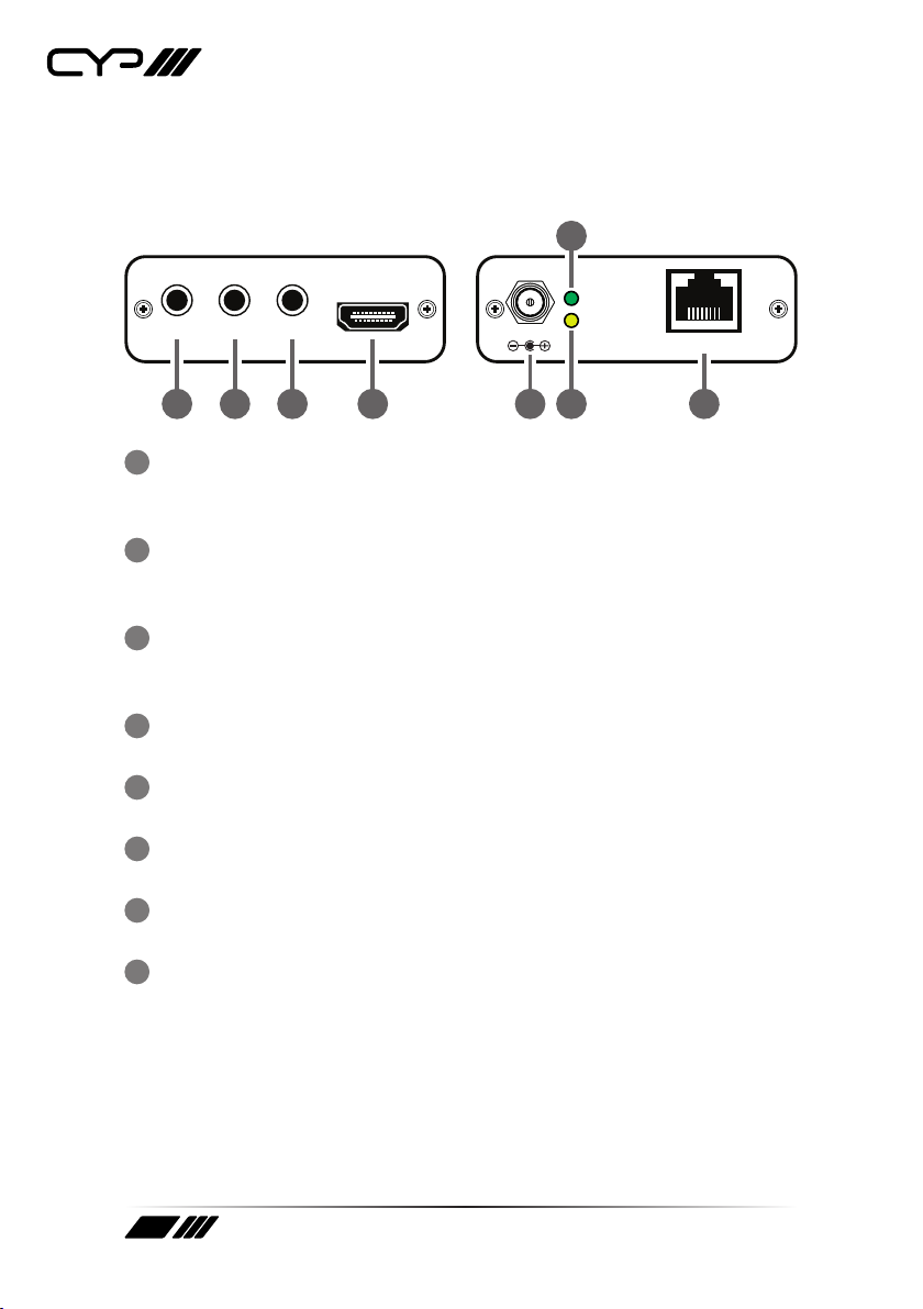
6.2 Receiver Front and Rear Panels
Power
Link
CAT 5e /6 In
DC 5V IR1 Extender
RS232 Out IR2 Blaster
HDMI Out
RearFront
675
18
3
2
4
1DC 5V: Plug the 5V DC power supply into the unit and connect the
adaptor to an AC outlet.
2Link: The yellow LED will illuminate when both the input and output
CAT5e/6/7 signals are connected.
3Power: This green LED will illuminate when the device is connected to
a power supply.
4CAT5e/6 In: Connect to the transmitter unit with a Single CAT5e/6/7
cable for transmission of all data signals.
5RS-232 Out: Connect to the device that is to be controlled (with
the supplied 3.5mm phone jack to D-Sub 9-pin adaptor) by RS-232
commands.
6IR1 Extender: Connect to the supplied IR extender cable for IR signal
reception. Ensure that remote being used is within the direct line-of-
sight of the IR extender.
7IR2 Blaster: Connect to the supplied IR blaster cable for IR signal
transmission. Place the IR blaster in direct line of sight of the
equipment to be controlled.
8HDMI Out: Connect to a HDMI equipped TV/monitor for display of the
HDMI input source signal.

10
6.3 D-Sub 9-Pin Denitions
PIN DEFINE TX/RX
1N/C
2TxD/RxD
3RxD/TxD
4N/C
5GND
6N/C
7N/C
8N/C
9N/C
6.4 IR Cable Pin Assignment
3
1
3
1
2
2
Power
IR Blaster Signal
NC
IR Signal
Power 5V
Ground
IR Extender
IR Blaster
Other manuals for PU-506-KIT
1
Table of contents
Other CYP Extender manuals


