O p e r a t i o n M a n u a l
4 MB39C326-EVBSK-01/02_SS901-00022-2v0-E, June 19, 2015
CONFIDENTIAL
Table of Contents
1. Description ..................................................................................................................................... 5
2. Evaluation Board Specification ....................................................................................................... 5
3. Block Diagram ................................................................................................................................ 6
4. PIN Descriptions ............................................................................................................................. 8
4.1 Input/Output Pin Descriptions .............................................................................................. 8
4.2 Jumper Descriptions............................................................................................................ 8
4.3 Setup and Verification ......................................................................................................... 8
5. Component and Wiring Layout ....................................................................................................... 9
5.1 Component Layout .............................................................................................................. 9
5.2 Wiring Layout .................................................................................................................... 11
6. Schematic Circuit.......................................................................................................................... 12
7. Component List ............................................................................................................................ 14
8. Evaluation Board Picture .............................................................................................................. 15
9. Ordering Information ..................................................................................................................... 16
10. Major Changes ............................................................................................................................. 17
Figures
Figure 1-1 Board Outline ............................................................................................................................ 5
Figure 3-1 Block Diagram for EVBSK-01 ................................................................................................... 6
Figure 3-2 Block Diagram for EVBSK-02 ................................................................................................... 7
Figure 4-1 Image of Connection ................................................................................................................. 8
Figure 5-1 Component Layout (Layer 1) .................................................................................................... 9
Figure 5-2 Component Layout (Layer 2, Top View) .................................................................................. 10
Figure 5-3 Wiring Layout (Layer 1) ............................................................................................................ 11
Figure 5-4 Wiring Layout (Layer 2, Top View) ........................................................................................... 11
Figure 6-1 Schematic Circuit for Power Save Mode ................................................................................. 12
Figure 6-2 Schematic Circuit for Fixed PWM Mode.................................................................................. 13
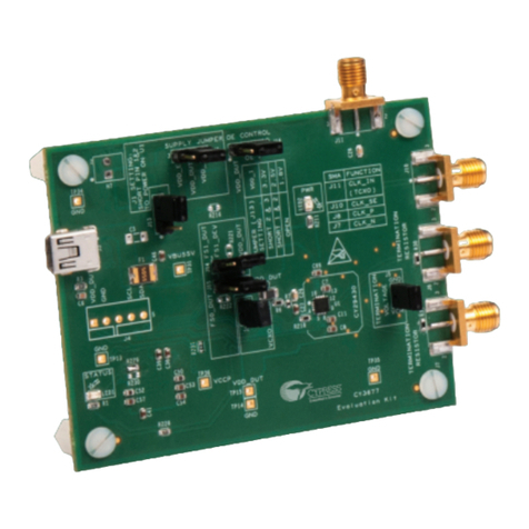
Figure 8-1 Picture of MB39C326-EVBSK-01 ............................................................................................ 15
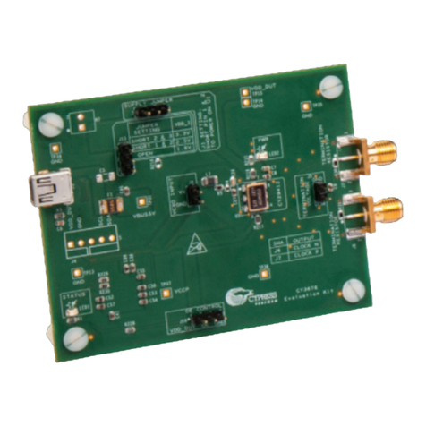
Figure 8-2 Picture of MB39C326-EVBSK-02 ............................................................................................ 15
Tables
Table 2-1 Evaluation Board Specification ................................................................................................... 5
Table 4-1 Input/Output Pin Descriptions ..................................................................................................... 8
Table 4-2 Jumper Descriptions ................................................................................................................... 8
Table 7-1 Component List ........................................................................................................................ 14
Table 9-1 Ordering Information ................................................................................................................. 16
