1. Review Kit Contents
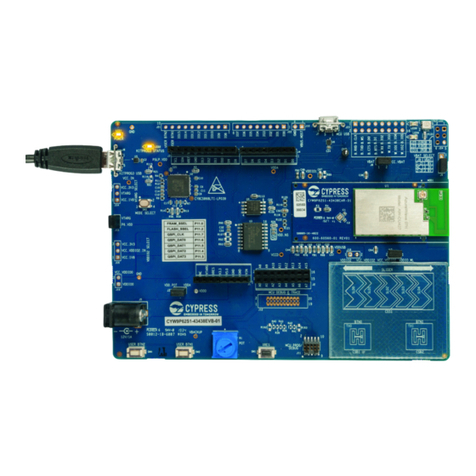
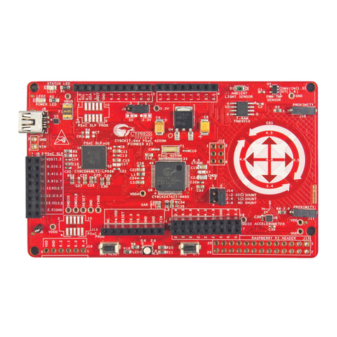
The CY3267 Kit consists of two hardware components:
■Main Board: This board consists of the PowerPSoC™ CY8CLED04DOCD
device, designed with a floating load buck topology to drive 1A to each of its four
output channels. The input power supply can come from the wall-wart connector
or the custom power supply screw terminals.
■LED Daughter Board: This board serves as a load to the Main Board. It consists
of a 10W 4-channel RGBA LED integrated into a single package.
Straight out of the box, this hardware can be used to demonstrate the ability of Pow-
erPSoC to function as an Intelligent LED Controller. The kit's default firmware demon-
strates 4-channel color mixing intelligence that drives the RGBA LED to produce any
desired color within its gamut and can be evaluated using the kit software GUI.
2. Kit Software
The CY3267 Kit comes with Cypress Intelligent Lighting Control GUI that enables con-
trol of the 4-channel LED Daughter Board. It enables you to select the desired color
point, output intensity or the desired shade of white on the Planckian Locus (Color
Temperature Control). It enables you to set the individual intensity of each of the four
colors of the RGBA LED.
2.1 GUI Installation Requirements
To use the application included with the CY3267 PowerPSoC Lighting Evaluation Kit, a
personal computer running Windows Vista or Windows XP is required. The application
runs under 32-bit XP or 32-bit Vista and requires at least 1 MB of free disk space.
2.2 GUI Installation Instructions
The Intelligent Lighting Control application is included on the kit CD. Use the following
procedure to install the application.
2.2.1. On the CY3267 PowerPSoC Lighting Evaluation Kit CD, locate the folder titled
Software. Open the folder and launch Intelligent Lighting Control.msi file.
2.2.2. Follow the on-screen instructions. This installs the Intelligent Lighting Control
application and the associated .dll files into the location C:\Program
Files\Cypress\Intelligent Lighting Control on your computer's default disk, usu-
ally drive C.
Page 10 Page 3
6. Safety Precautions
General Safety Precautions
6.1. Keep your work area clean. Ensure that there are no loose wires or metal pieces
lying on the table or nearby high-power circuits.
6.2. Always wear safety glasses when working with circuits at high power or high volt-
age.
6.3. Use rubber floor mats to insulate you from ground.
6.4. Be aware of bracelets, rings, metal watch bands and loose necklace/pendants
that you may be wearing. They conduct electricity and can cause burns. Do not
wear them near an energized circuit.
6.5. Be aware of the locations of fire extinguishers and first aid kits in the lab and
around your work area.
6.6. Use only isolated power supplies (either isolated or AC power through isolation
power transformers).
6.7. Before applying power to your circuit, verify that all connections are correct as
per the board schematic. Ensure that there are no shorts or ground loops that
may lead to electrical shocks or damage the test equipment.
Precautions when working with PowerPSoC based high-power
circuits
6.8. When building your own system with the CY3267 for the first time, begin with low
current settings (preferably 50mA). Set the DAC thresholds in the PowerPSoC's
hysteretic controller accordingly. Once the system functions as desired at this
current setting, increase the hysteretic controller's DAC thresholds in steady
increments to the final value. At each increment, verify that the components on
the board are not excessively hot.
6.9. Ensure that the high-side DAC reference and the low-side DAC reference differ
by a count of at least four. For example, if the low-side DAC reference is set to 85
(decimal representation), the high-side DAC reference should be set to at least
89.
6.10. Follow the FET Turn-On sequence suggested in the example project. Altering
this sequence may damage the PowerPSoC's internal FETs.
