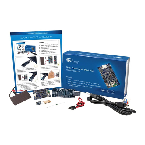
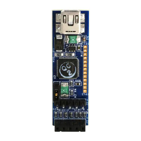
Cypress PSoC CY8CKIT-062-WiFi-BT User manual

www.infineon.com
Please note that Cypress is an Infineon Technologies Company.
The document following this cover page is marked as “Cypress” document as this is the
company that originally developed the product. Please note that Infineon will continue
to oer the product to new and existing customers as part of the Infineon product
portfolio.
Continuity of document content
The fact that Infineon oers the following product as part of the Infineon product
portfolio does not lead to any changes to this document. Future revisions will occur
when appropriate, and any changes will be set out on the document history page.
Continuity of ordering part numbers
Infineon continues to support existing part numbers. Please continue to use the
ordering part numbers listed in the datasheet for ordering.

Copyrights
PSoC™ 6 Wi-Fi Bluetooth® pioneer kit guide, Document Number. 002-22677 Rev. *I 2
Copyrights
© Cypress Semiconductor Corporation, 2018–2022. This document is the property of Cypress Semiconductor Corporation
and its subsidiaries, including Spansion LLC (“Cypress”). This document, including any software or firmware included or
referenced in this document (“Software”), is owned by Cypress under the intellectual property laws and treaties of the United
States and other countries worldwide. Cypress reserves all rights under such laws and treaties and does not, except as
specifically stated in this paragraph, grant any license under its patents, copyrights, trademarks, or other intellectual property
rights. If the Software is not accompanied by a license agreement and you do not otherwise have a written agreement with
Cypress governing the use of the Software, then Cypress hereby grants you a personal, non-exclusive, nontransferable
license (without the right to sublicense) (1) under its copyright rights in the Software (a) for Software provided in source code
form, to modify and reproduce the Software solely for use with Cypress hardware products, only internally within your
organization, and (b) to distribute the Software in binary code form externally to end users (either directly or indirectly through
resellers and distributors), solely for use on Cypress hardware product units, and (2) under those claims of Cypress's patents
that are infringed by the Software (as provided by Cypress, unmodified) to make, use, distribute, and import the Software
solely for use with Cypress hardware products. Any other use, reproduction, modification, translation, or compilation of the
Software is prohibited.
TO THE EXTENT PERMITTED BY APPLICABLE LAW, CYPRESS MAKES NO WARRANTY OF ANY KIND, EXPRESS OR
IMPLIED, WITH REGARD TO THIS DOCUMENT OR ANY SOFTWARE OR ACCOMPANYING HARDWARE, INCLUDING,
BUT NOT LIMITED TO, THE IMPLIED WARRANTIES OF MERCHANTABILITY AND FITNESS FOR A PARTICULAR
PURPOSE. No computing device can be absolutely secure. Therefore, despite security measures implemented in Cypress
hardware or software products, Cypress does not assume any liability arising out of any security breach, such as
unauthorized access to or use of a Cypress product. In addition, the products described in these materials may contain
design defects or errors known as errata which may cause the product to deviate from published specifications. To the extent
permitted by applicable law, Cypress reserves the right to make changes to this document without further notice.
Cypress does not assume any liability arising out of the application or use of any product or circuit described in this document.
Any information provided in this document, including any sample design information or programming code, is provided only
for reference purposes. It is the responsibility of the user of this document to properly design, program, and test the
functionality and safety of any application made of this information and any resulting product. Cypress products are not
designed, intended, or authorized for use as critical components in systems designed or intended for the operation of
weapons, weapons systems, nuclear installations, life-support devices or systems, other medical devices or systems
(including resuscitation equipment and surgical implants), pollution control or hazardous substances management, or other
uses where the failure of the device or system could cause personal injury, death, or property damage ("Unintended Uses"). A
critical component is any component of a device or system whose failure to perform can be reasonably expected to cause the
failure of the device or system, or to affect its safety or effectiveness. Cypress is not liable, in whole or in part, and you shall
and hereby do release Cypress from any claim, damage, or other liability arising from or related to all Unintended Uses of
Cypress products. You shall indemnify and hold Cypress harmless from and against all claims, costs, damages, and other
liabilities, including claims for personal injury or death, arising from or related to any Unintended Uses of Cypress products.
Cypress, the Cypress logo, Spansion, the Spansion logo, and combinations thereof, WICED, PSoC, CapSense, EZ-USB,
F-RAM, and Traveo are trademarks or registered trademarks of Cypress in the United States and other countries. For a more
complete list of Cypress trademarks, visit cypress.com. Other names and brands may be claimed as property of their
respective owners.

PSoC™ 6 Wi-Fi Bluetooth® pioneer kit guide, Document Number. 002-22677 Rev. *I 3
Contents
Safety and regulatory compliance information 5
1. Introduction 7
1.1 Kit contents ..................................................................................................................8
1.2 Getting started .............................................................................................................8
1.3 Board details................................................................................................................9
1.3.1 CY8CKIT-062-WIFI-BT board details...............................................................9
1.3.2 CY8CKIT-028-TFT board details....................................................................18
1.4 Additional learning resources ....................................................................................20
1.5 Technical support ......................................................................................................20
1.6 Documentation conventions ......................................................................................20
1.7 Acronyms...................................................................................................................20
2. Kit operation 22
2.1 Theory of operation....................................................................................................22
2.2 CY8CKIT-028-TFT details .........................................................................................27
2.2.1 CY8CKIT-028-TFT display shield...................................................................27
2.3 KitProg3: On-board programmer/debugger ...............................................................30
2.3.1 Programming and debugging using ModusToolbox™ software.....................30
2.3.2 USB-UART bridge ..........................................................................................34
2.3.3 USB-I2C bridge ..............................................................................................35
2.3.4 USB-SPI bridge..............................................................................................35
3. Hardware 36
3.1 Schematics ................................................................................................................36
3.2 Hardware functional description ................................................................................36
3.2.1 PSoC™ 6 MCU (U1) ......................................................................................36
3.2.2 PSoC™ 5LP (U2)...........................................................................................36
3.2.3 Serial interconnection between PSoC™ 5LP and PSoC™ 6 MCU ...............37
3.2.4 Power supply system .....................................................................................38
3.2.5 Expansion connectors....................................................................................41
3.2.6 CAPSENSE™ circuit......................................................................................42
3.2.7 LEDs ..............................................................................................................42
3.2.8 Push buttons ..................................................................................................43
3.2.9 NOR flash.......................................................................................................43
3.2.10 Quad SPI F-RAM ...........................................................................................44
3.2.11 Wi-Fi and Bluetooth® module ........................................................................45
3.2.12 USB host and USB device connections .........................................................46
3.3 PSoC™ 6 Wi-Fi Bluetooth® pioneer board reworks..................................................47
3.3.1 Bypass protection circuit on program and debug header (J11)......................47
3.3.2 PSoC™ 6 MCU user button (SW2)................................................................48
3.3.3 SWD connector receptacle (J29) ...................................................................48

PSoC™ 6 Wi-Fi Bluetooth® pioneer kit guide, Document Number. 002-22677 Rev. *I 4
Contents
3.3.4 CAPSENSE™ shield......................................................................................49
3.3.5 CSH................................................................................................................49
3.3.6 Multiplexed GPIOs .........................................................................................50
3.4 Bill of materials ..........................................................................................................50
3.5 Frequently asked questions.......................................................................................50
Revision History 54

PSoC™ 6 Wi-Fi Bluetooth® pioneer kit guide, Document Number. 002-22677 Rev. *I 5
Safety and regulatory compliance
information
Regulatory compliance information
Contains transmitter module FCC ID: VPYLB1DX and IC: 772C-LB1DX
This kit is intended to use for ENGINEERING DEVELOPMENT, DEMONSTRATION, OR
EVALUATION PURPOSES ONLY and is not considered by Cypress Semiconductor to be a finished
end-product fit for general consumer use. It generates, uses, and can radiate radio-frequency
energy and has not been tested for compliance with the limits of computing devices pursuant to part
15 of FCC or ICES-003 rules, which are designed to provide reasonable protection against radio-
frequency interference. Operation of the equipment may cause interference with radio
communications, in which case users at their own expense will be required to take whatever
measures may be required to correct this interference.
The kit contains Type 1DX (LBEE5KL1DX) certified module from Murata. Due to change in the
antenna pattern/type and gain used in this kit, Class II permissive changes are required to recertify
this kit. The radiated emission tests must be performed again to obtain a new FCC ID for this host
kit. Most conducted RF test results may still be reused. Customer also needs to take their product
through other FCC/ISED testing such as unintentional radiators (FCC sub part 15B) and any other
required regional product certifications including but not limited to EU directives. See FCC
Regulatory Certification Guide by Murata on information on pre-certified and reference certified
module concepts and information on what additional test are required for FCC certification.
Customer should consult a Telecommunication Certification Body (TCB) lab for guidance on other
requirements for the device certification.
For details on the Type 1DX module from Murata, see https://wireless.murata.com/type-1dx.html.
This kit contains electrostatic discharge (ESD)-sensitive devices.
Electrostatic charges readily accumulate on the human body and any
equipment, and can discharge without detection. Permanent damage
may occur on devices subjected to high-energy discharges. Proper
ESD precautions are recommended to avoid performance degradation
or loss of functionality. Store unused kits in the protective shipping
package.
End-of-Life/Product Recycling
The end-of life for this kit is five years from the date of manufacture
mentioned as a bar code on the back of the kit box. Contact your
nearest recycler for information on discarding the kit.

PSoC™ 6 Wi-Fi Bluetooth® pioneer kit guide, Document Number. 002-22677 Rev. *I 6
General safety instructions
ESD protection
ESD can damage boards and associated components. Cypress recommends that you perform
procedures only at an ESD workstation. If an ESD workstation is unavailable, use appropriate ESD
protection by wearing an anti-static wrist strap attached to a grounded metal object.
Handling boards
This kit is sensitive to ESD. Hold the board only by its edges. After removing the board from its box,
place it on a grounded, static-free surface. Use a conductive foam pad, if available. Do not slide the
board over any surface.

PSoC™ 6 Wi-Fi Bluetooth® pioneer kit guide, Document Number. 002-22677 Rev. *I 7
1. Introduction
Thank you for your interest in the CY8CKIT-062-WIFI-BT PSoC™ 6 Wi-Fi Bluetooth® pioneer kit.
This kit enables you to evaluate and develop your applications using the PSoC™ 6 MCU.
The PSoC™ 6 MCU is an ultra-low-power PSoC™ device specifically designed for wearables and
IoT products. It is a programmable embedded system-on-chip, integrating a 150-MHz Arm®
Cortex®-M4 as the primary application processor, a 100-MHz CM0+ that supports low-power
operations, up to 1 MB flash and 288 KB SRAM, CAPSENSE™ touch-sensing, and programmable
analog and digital peripherals that allow higher flexibility, in-field tuning of the design, and faster
time-to-market.
The PSoC™ 6 Wi-Fi Bluetooth® pioneer board offers compatibility with shields compatible with
Arduino. The board features a PSoC™ 6 MCU, a 512-Mb NOR flash, an on-board programmer/
debugger (KitProg3), a 2.4-GHz WLAN and Bluetooth® functionality module (CYW4343W), a five-
segment CAPSENSE™ slider, two CAPSENSE™ buttons, one CAPSENSE™ proximity sensing
header, an RGB LED, two user LEDs, USB host and device features, and one push button. The
board supports operating voltages from 1.8 V to 3.3 V for the PSoC™ 6 MCU.
The kit package includes a CY8CKIT-028-TFT display shield that contains a 2.4-inch TFT display, a
motion sensor, ambient light sensor, a 32-bit audio codec, and a PDM microphone.
You can use ModusToolbox™ software to develop and debug your PSoC™ 6 MCU projects.
ModusToolbox™ software is a set of tools that enable you to integrate Cypress devices into your
existing development methodology.
If you are new to PSoC™ 6 MCU and Eclipse IDE for ModusToolbox™ software, see the application
note AN228571 - Getting started with PSoC™ 6 MCU on ModusToolbox™ software to help you
familiarize with the PSoC™ 6 MCU and help you create your own design using the ModusToolbox™
software.

PSoC™ 6 Wi-Fi Bluetooth® pioneer kit guide, Document Number. 002-22677 Rev. *I 8
Introduction
1.1 Kit contents
The kit package has the following contents, as shown in Figure 1-1.
■PSoC™ 6 Wi-Fi Bluetooth® pioneer board
■CY8CKIT-028-TFT display shield
■USB Type-A to Type-C cable
■Four jumper wires (4 inches each)
■Two proximity sensor wires (5 inches each)
■Quick start guide
Figure 1-1. Kit contents
Inspect the contents of the kit; if you find any part missing, contact your nearest Cypress sales office
for help: www.cypress.com/support.
1.2 Getting started
This guide will help you to get acquainted with the PSoC™ 6 Wi-Fi Bluetooth® pioneer kit:
■The Kit operation chapter on page 22 describes the CY8CKIT-062-WIFI-BT baseboard and
CY8CKIT-028-TFT shield hardware features and functionalities.
■The Hardware on page 36 provides a detailed hardware description, methods to use the
on-board components, kit schematics, the bill of materials (BOM), and an FAQ.

PSoC™ 6 Wi-Fi Bluetooth® pioneer kit guide, Document Number. 002-22677 Rev. *I 9
Introduction
1.3 Board details
1.3.1 CY8CKIT-062-WIFI-BT board details
Figure 1-2 shows the pioneer board, which has the following features:
■PSoC™ 6 MCU
■Expansion headers that are compatible with Arduino Uno 3.3-V shields1 and Digilent Pmod
modules
■Type 1DX ultra-small 2.4-GHz WLAN and Bluetooth® functionality module
■512-Mbit external quad-SPI NOR flash that provides a fast, expandable memory for data and
code
■KitProg3 onboard programmer/debugger, USB to UART/I2C/SPI bridge functionality
■CAPSENSE™ touch-sensing slider (five elements) and two buttons, all of which are capable of
both self-capacitance (CSD) and mutual-capacitance (CSX) operation, and a CSD proximity
sensor that allows you to evaluate Cypress’ fourth-generation CAPSENSE™ technology
■1.8-V to 3.3-V operation of PSoC™ 6 MCU is supported. An additional 330-mF super-capacitor is
provided for backup domain supply (VBACKUP)
■Two user LEDs, an RGB LED, a user button, and a reset button for PSoC™ 6 MCU.
■One button and three LEDs for KitProg3.
1. 5-V shields are not supported.

PSoC™ 6 Wi-Fi Bluetooth® pioneer kit guide, Document Number. 002-22677 Rev. *I 10
Introduction
Figure 1-2. Pioneer board
тѷ &1/,$ф6-"Ҍ ,++" 1,/ҙтсҚ
уѷ &1/,$ф-/,$/**&+$*,!"0")" 1&,+211,+ҙфҚ
фѷ &1/,$фҟ%"!"/ҙчҚң
хѷ &1/,$ф-/,$/**&+$ҟ%"!"/ҙшҚң
цѷ 51"/+)-,4"/02--)6 ,++" 1,/ҙъҚ
чѷ ,ч20"/211,+ҙуҚ
шѷ ҟ%"!"/ ,*-1&)"4&1%&$&)"+1*,!ҙтхҚң
щѷ ,4"/ҙхҚ
ъѷ &1/,$ф011200ҙтѸуѸфҚ
тсѷ ,ч/"0"1211,+ҙтҚ
ттѷ ,чҟ%"!"/0ҙтщѸтъѸусҚ
туѷ ,4"/%"!"/ ,*-1&)"4&1%/!2&+,+,фҙтҚ
тфѷ ,ч!"2$+!1/ "%"!"/ҙтуҚ
тхѷ ҟ%"!"/0 ,*-1&)"4&1%
/!2&+,+,фҙуѸфѸхҚ
тцѷ,ч-/,$/*+!!"2$%"!"/ҙттҚ
*Footprints only, not populated on the board
**Components at the bottom side of the board
тчѷ-/,5&*&16%"!"/ҙтфҚ
тшѷ0)&!"/+!211,+0ҙсѸтѸҚ
тщѷ ,ч0")" 1&,+04&1 %ҙцҚ
тъѷ +#&+",+цтуҌ&10"/&)#)0%*"*,/6ҙуццтуѸхҚ
усѷ ,ч20"/0ҙщѸъҚ
утѷ ҙцҚ
ууѷ &Ҍ&ҟ)2"1,,1%Һ*,!2)"ҙцтѸчҚ
уфѷ +#&+",+)1/2!ҌҌҙтцтсхѸцҚ
ухѷ &Ҍ&Ҍ)2"1,,1%Һ+1"++ҙтҚ
уцѷ+! ,+1/,)0")" 1&,+04&1 %ҙшҚңң
учѷ ,ч!"3& "6-"Ҍ ,++" 1,/ҙущҚ
ушѷ ,чҙщчухшҌцхѸтҚ
ущѷ ,ч%,016-"Ҍ ,++" 1,/ҙушҚ
уъѷ %"!"/ ,*-1&)"4&1%/!2&+,+,фҙцҚң
фсѷ ,ч-,4"/*,+&1,/&+$'2*-"/ҙщҚңң
фтѷ &1/,$ф-/,$/**"/+!!"2$$"/0"!,+,ц
ҙщцщчщҌсфъѸуҚ
т
у
ф
х
ц
чшщътс тт ту тф тх тц тш
тщ
тъ
ус
ут
уу
уф
ух
уч уцуш
ущ
уъфс
тч
тт тт тх
тх фт

PSoC™ 6 Wi-Fi Bluetooth® pioneer kit guide, Document Number. 002-22677 Rev. *I 11
Introduction
Figure 1-3. Pioneer board pinout

PSoC™ 6 Wi-Fi Bluetooth® pioneer kit guide, Document Number. 002-22677 Rev. *I 12
Introduction
Table 1-1. Pioneer board pinout
PSoC™ 6
pin
Primary
on-board function
Secondary
on-board function Connection details
XRES Reset –
P0.0 WCO IN –
P0.1 WCO OUT –
P0.2 Header compatible with
Arduino J4.8, D7 –
P0.3 RGB LED (red) –
P0.4 User button with Hiber-
nate wakeup capability –
P0.5 PMIC control –
P1.0 CAPSENSE™ Tx
GPIO on
non-Arduino header
(J19.5)
Populate R174 to connect to the header or
remove R62 to disconnect from CAPSENSE™.
P1.1 RGB LED (green) –
P1.2 GPIO on non-Arduino
header (J19.4) –
P1.3 GPIO on non-Arduino
header (J19.3) –
P1.4 GPIO on non-Arduino
header (J19.2) –
P1.5 User LED (orange)
GPIO on
non-Arduino header
(J19.1)
Connected to primary and secondary functions
by default. Remove R27 to disconnect from the
LED.
P2.0 SDIO DATA0 J25.7
(WL_JTAG_TMS)
Remove R122 (or R110) and mount R115 to
disconnect from PSoC™ 6 MCU and connect
the Wi-Fi/Bluetooth® module to the JTAG
connector.
P2.1 SDIO DATA1 J25.3
(WL_JTAG_TDI)
Remove R32 (or R111) and mount R116 to
disconnect from PSoC™ 6 MCU and connect
the Wi-Fi/Bluetooth® module to the JTAG
connector.
P2.2 SDIO DATA2 J25.5
(WL_JTAG_TDO)
Remove R128 (or R112) and mount R117 to
disconnect from PSoC™ 6 MCU and connect
the Wi-Fi/Bluetooth® module to the JTAG
connector.
P2.3 SDIO DATA3 J25.1
(WL_JTAG_TRSTN)
Remove R109 (or R132) and mount R114 to
disconnect from PSoC™ 6 MCU and connect
the Wi-Fi/Bluetooth® module to the JTAG
connector.
P2.4 SDIO CMD –
P2.5 SDIO CLK J25.9
(WL_JTAG_TCK)
Remove R108 (or R28) and mount R113 to
disconnect from PSoC™ 6 MCU and connect
the Wi-Fi/Bluetooth® module to the JTAG
connector.

PSoC™ 6 Wi-Fi Bluetooth® pioneer kit guide, Document Number. 002-22677 Rev. *I 13
Introduction
P3.0 BT UART TXD – BT UART TXD pin of the Wi-Fi/Bluetooth®
module
P3.1 BT UART RXD – BT UART RXD pin of the Wi-Fi/Bluetooth®
module
P3.2 BT UART CTS – BT UART CTS pin of the Wi-Fi/Bluetooth®
module
P3.3 BT UART RTS – BT UART RTS pin of the Wi-Fi/Bluetooth®
module
P3.4 BT REG ON – BT REG ON pin of the Wi-Fi/Bluetooth® module
P3.5 BT HOST WAKE – BT HOST WAKE pin of the Wi-Fi/Bluetooth®
module
P4.0 BT DEV WAKE – BT DEV WAKE pin of the Wi-Fi/Bluetooth®
module
P4.1 Header J21.1 –
P5.0
Arduino J4.1, D0
UART RX
KitProg3 UART TX
–Remove R159 to disconnect from KitProg3
UART TX.
P5.1
Arduino J4.2, D1
UART TX
KitProg3 UART RX
–Remove R156 to disconnect from KitProg3
UART RX.
P5.2
Arduino J4.3, D2
UART RTS
KitProg3 UART CTS
–
Remove R93 to disconnect from KitProg3
UART CTS. This will also disconnect RTS and
SPI lines from KitProg3.
P5.3
Arduino J4.4, D3
UART CTS
KitProg3 UART RTS
–
Remove R88 to disconnect from KitProg3
UART RTS. This will also disconnect CTS and
SPI lines from KitProg3.
P5.4 Arduino J4.5, D4 –
P5.5 Arduino J4.6, D5 –
P5.6 Arduino J4.7, D6 –
P5.7 Header J21.3 –
P6.0 Arduino J3.10, SCL
KitProg3 I2C SCL –Remove R141 to disconnect from KitProg3 I2C
SCL.
P6.1 Arduino J3.9, SDA
KitProg3 I2C SDA –Remove R150 to disconnect from KitProg3 I2C
SDA.
P6.2 GPIO on non-Arduino
header (J2.15) –
P6.3 GPIO on non-Arduino
header (J2.17)
CAPSENSE™
shield
Remove R44 to disconnect from GND and
populate R145 to connect to the CAPSENSE™
shield (hash pattern on the board).
P6.4 TDO/SWO –
P6.5 TDI –
P6.6 TMS/SWDIO – Remove R194 to disconnect from KitProg3
SWDIO.
Table 1-1. Pioneer board pinout (continued)
PSoC™ 6
pin
Primary
on-board function
Secondary
on-board function Connection details

PSoC™ 6 Wi-Fi Bluetooth® pioneer kit guide, Document Number. 002-22677 Rev. *I 14
Introduction
P6.7 TCLK/SWCLK – Remove R183 to disconnect from KitProg3
SWCLK.
P7.0 TRACECLK
GPIO on
non-Arduino header
(J18.6)
Populate R181 to connect to J18 header.
P7.1 CINTA –
P7.2 CINTB CSH Remove C31 (0.47 nF) and populate 10 nF for
CSH.
P7.3 GPIO on non-Arduino
header (J18.5) CSH Remove R146 to disconnect from header and
populate C29 (10 nF) for CSH.
P7.4 TRACEDATA[3]
GPIO on
non-Arduino header
(J18.4)
Populate R178 to connect to J18.
P7.5 TRACEDATA[2]
GPIO on
non-Arduino header
(J18.3)
Populate R179 to connect to J18.
P7.6 TRACEDATA[1]
GPIO on
non-Arduino header
(J18.2)
Populate R180 to connect to J18.
P7.7 CMOD
GPIO on
non-Arduino header
(J18.1)
Populate R142 to connect to J18.
P8.0 Proximity
GPIO on
non-Arduino header
(J20.1)
Populate R64 with zero ohm to connect to
header.
P8.1 CAPSENSE™ Button0 Rx
GPIO on
non-Arduino header
(J20.2)
Remove R61 to disconnect CAPSENSE™ pad
and populate R172 to connect to header.
P8.2 CAPSENSE™ Button1 Rx
GPIO on
non-Arduino header
(J20.3)
Remove R60 to disconnect CAPSENSE™ pad
and populate R166 to connect to header.
P8.3 CAPSENSE™ Silder0 Rx
GPIO on
non-Arduino header
(J20.4)
Remove R53 to disconnect CAPSENSE™ pad
and populate R153 to connect to header.
P8.4 CAPSENSE™ Silder1 Rx
GPIO on
non-Arduino header
(J20.5)
Remove R52 to disconnect CAPSENSE™ pad
and populate R152 to connect to header.
P8.5 CAPSENSE™ Silder2 Rx
GPIO on
non-Arduino header
(J20.6)
Remove R47 to disconnect CAPSENSE™ pad
and populate R149 to connect to header.
P8.6 CAPSENSE™ Silder3 Rx
GPIO on
non-Arduino header
(J20.7)
Remove R58 to disconnect CAPSENSE™ pad
and populate R158 to connect to header.
P8.7 CAPSENSE™ Silder4 Rx
GPIO on
non-Arduino header
(J20.8)
Remove R59 to disconnect CAPSENSE™ pad
and populate R160 to connect to header.
P9.0 GPIO on non-Arduino
header (J2.2) –
Table 1-1. Pioneer board pinout (continued)
PSoC™ 6
pin
Primary
on-board function
Secondary
on-board function Connection details

PSoC™ 6 Wi-Fi Bluetooth® pioneer kit guide, Document Number. 002-22677 Rev. *I 15
Introduction
P9.1 GPIO on non-Arduino
header (J2.4) –
P9.2 GPIO on non-Arduino
header (J2.6) –
P9.3 TRACEDATA[0]
GPIO on
non-Arduino header
(J2.8)
Populate R162 to connect to header.
P9.4 GPIO on non-Arduino
header (J2.10) –
P9.5 GPIO on non-Arduino
header (J2.12) –
P9.6 GPIO on non-Arduino
header (J2.16) –
P9.7 GPIO on non-Arduino
header (J2.18) –
P10.0
GPIO on header
compatible with Arduino
J2.1, A0
–
P10.1
GPIO on header
compatible with Arduino
J2.3, A1
–
P10.2
GPIO on header
compatible with Arduino
J2.5, A2
–
P10.3
GPIO on header
compatible with Arduino
J2.7, A3
–
P10.4
GPIO on header
compatible with Arduino
J2.9, A4
PDM_CLK
–
P10.5
GPIO on header
compatible with Arduino
J2.11, A5
PDM_DAT
–
P10.6 GPIO on non-Arduino
header (J2.13) –
P10.7 Header J21.5 –
P11.0 FRAM CS
GPIO on
non-Arduino header
(J18.8)
Connected to primary and secondary functions
by default. Remove R175 to disconnect from
J18 and load R39 (10K) as F-RAM pull-up.
P11.1 RGB Blue LED –
P11.2 QSPI FLASH CS
GPIO on
non-Arduino header
(J18.7)
Populate R177 to connect to J18, remove R176
to disconnect from flash.
P11.3 QSPI FLASH/
FRAM DATA3 –
Table 1-1. Pioneer board pinout (continued)
PSoC™ 6
pin
Primary
on-board function
Secondary
on-board function Connection details

PSoC™ 6 Wi-Fi Bluetooth® pioneer kit guide, Document Number. 002-22677 Rev. *I 16
Introduction
P11.4 QSPI FLASH/
FRAM DATA2 –
P11.5 QSPI FLASH/
FRAM DATA1 –
P11.6 QSPI FLASH/
FRAM DATA0 –
P11.7 QSPI FLASH/
FRAM CLK –
P12.0
J3.4 on header compatible
with Arduino, D11
SPI MOSI
ICSP header (J5.4)
and Pmod header
(J14.2)
Remove R77 to disconnect from KitProg3_SPI
lines.
P12.1
J3.5 on header compatible
with Arduino, D12
SPI MISO
ICSP header (J5.1)
and Pmod header
(J14.3)
Remove R85 to disconnect from KitProg3_SPI
lines.
P12.2
J3.6 on header compatible
with Arduino, D13
SPI CLK
ICSP header (J5.3)
and header
compatible with
Pmod (J14.4)
Remove R81 to disconnect from KitProg3_SPI
lines.
P12.4 KitProg3 SPI SELECT
GPIO on
non-Arduino header
(J19.10)
Connected to primary function by default.
Populate R74 to connect to J19 or remove R83
to disconnect KitProg3_SPI_SELECT.
P12.5 PMOD SPI SELECT, J14.1
GPIO on
non-Arduino header
(J19.9)
Connected to primary and secondary functions
by default. Remove R73 to disconnect from J19
or remove R82 to disconnect
PMOD_SPI_SELECT.
P12.6 ECO IN
GPIO on
non-Arduino header
(J19.8)
P12.7 ECO OUT
GPIO on
non-Arduino header
(J19.6)
P13.0
GPIO on header
compatible with Arduino
J3.1, D8
–
P13.1
GPIO on header
compatible with Arduino
J3.2, D9
–
P13.2 USB HOST EN
GPIO on
non-Arduino header
(J21.2)
P13.3 USB_INT_L
GPIO on
non-Arduino header
(J21.4)
Table 1-1. Pioneer board pinout (continued)
PSoC™ 6
pin
Primary
on-board function
Secondary
on-board function Connection details

PSoC™ 6 Wi-Fi Bluetooth® pioneer kit guide, Document Number. 002-22677 Rev. *I 17
Introduction
P13.4 USB_DEV_VBUS_DET
GPIO on
non-Arduino header
(J21.6)
P13.5 GPIO on non-Arduino
header J21.8 –
P13.6 GPIO on non-Arduino
header J2.19
CAPSENSE™
shield
Remove R44 to disconnect from GND and
populate R45 to connect to the CAPSENSE™
shield (hash pattern on the board).
P13.7 User LED (red)
GPIO on
non-Arduino header
(J2.20)
Remove R31 to disconnect from LED.
Table 1-1. Pioneer board pinout (continued)
PSoC™ 6
pin
Primary
on-board function
Secondary
on-board function Connection details

PSoC™ 6 Wi-Fi Bluetooth® pioneer kit guide, Document Number. 002-22677 Rev. *I 18
Introduction
1.3.2 CY8CKIT-028-TFT board details
Figure 1-4 shows the TFT display shield that has the following features:
■A 2.4-inch thin-film transistor (TFT) LCD module with 240 × 320 pixel resolution.
■A three-axis acceleration and three-axis gyroscopic motion sensor.
■A PDM microphone for voice input.
■A 32-bit stereo codec with microphone, headphone, and speaker amplifier capability.
■An audio jack with a provision of connecting both AHJ and OMTP headphones. The headset
standard can be set by an on-board switch.
■An ambient light sensor IC made of an NPN phototransistor.
■An LDO that converts 3.3 V to 1.8 V for the digital supply of the audio codec.
Figure 1-4. TFT display shield
1. 2.4-inch TFT display
2. Motion sensor (U1)
3. Ambient light sensor (Q1)
4. PDM microphone (U2)
5. I/O headers compatible with Arduino (J2,
J3, J4)
6. Power header compatible with Arduino
(J1)
7. TFT display power control load switch (U4)
8. TFT display connector (J5)
9. Audio codec (U3)
10. Audio jack (J6)
11. Audio jack selection (OMTP/AHJ) switch
(SW1)

PSoC™ 6 Wi-Fi Bluetooth® pioneer kit guide, Document Number. 002-22677 Rev. *I 19
Introduction
Table 1-2. TFT shield pinout
Pin # Arduino pin Arduino
function TFT shield function Pioneer board
connection
J1.1 VIN VIN NC VIN
J1.2 GND GND GND GND
J1.3 GND GND GND GND
J1.4 5 V 5 V NC 5 V
J1.5 3.3 V 3.3 V VCC 3.3V 3.3 V
J1.6 RESET RESET NC SWD RESET
J1.7 I/O REF I/O REF VIO REF P6 VDD
J1.8 – – NC NC
J2.1 A0 ADC0 ALS OUT P10[0]
J2.2 – – TFT DISP DB8 P9[0]
J2.3 A1 ADC1 Codec PDN SW P10[1]
J2.4 – – TFT DISP DB9 P9[1]
J2.5 A2 ADC2 IMU INT1 P10[2]
J2.6 – – TFT DISP DB10 P9[2]
J2.7 A3 ADC3 IMU INT2 P10[3]
J2.8 – – NC P9[3]
J2.9 A4 ADC4 / SDA
(I2C) PDM CLK P10[4]
J2.10 – – TFT DISP DB11 P9[4]a
a. Mount R162 (on the Pioneer board) to connect J2.10 of the TFT board to P9[4].
J2.11 A5 ADC5 PDM DATA P10[5]
J2.12 – – TFT DISP DB12 P9[5]
J3.1 D8 DIGITAL I/O TFT DISP DB14 P13[0]
J3.2 D9 PWM TFT DISP DB15 P13[1]
J3.3 D10 SS/PWM TFT DISP RD_L P12[3]
J3.4 D11 MOSI/PWM TFT DISP WR_L P12[0]
J3.5 D12 MISO TFT DISP D/C P12[1]
J3.6 D13 SCK TFT DISP RST_L P12[2]
J3.7 GND GND GND GND
J3.8 AREF analog ref i/p NC VREF
J3.9 SDA SDA I2C SDA (IMU and audio codec) P6[1]
J3.10 SCL SCL I2C SCL (IMU and audio codec) P6[0]
J4.1 D0 RX I2S MCLK P5[0]
J4.2 D1 TX I2S TX SCK P5[1]
J4.3 D2 DIGITAL I/O I2S TX WS P5[2]
J4.4 D3 PWM, I/O I2S TX SDO P5[3]
J4.5 D4 DIGITAL I/O I2S RX SCK P5[4]
J4.6 D5 PWM, I/O I2S RX WS P5[5]
J4.7 D6 PWM, I/O I2S RX SDI P5[6]
J4.8 D7 DIGITAL I/O TFT DISP DB13 P0[2]
Other manuals for PSoC CY8CKIT-062-WiFi-BT
2
Table of contents
Other Cypress Network Hardware manuals
Popular Network Hardware manuals by other brands

COMCRAFT
COMCRAFT 100UTP Portable user manual

Bay Networks
Bay Networks CLAM installation guide

ZyXEL Communications
ZyXEL Communications GS3700 Series user guide

ADTRAN
ADTRAN Total Access 1248 Specifications

ADTRAN
ADTRAN DSU IV ESP user manual

SMC Networks
SMC Networks ELITECONNECT SMC2502W installation manual