Cypress HHR-4000 User manual

Page of1 31
Wireless Handheld Reader
with OSDP™ Secure Channel
HHR-4000 Single-Lane Kits
Product Manual
Cypress Integration Solutions 35+ Years of Access Control Ingenuity CypressIntegration.com
© 2021 Cypress Computer Systems 1778 Imlay City Road, Lapeer, MI 48446 800-807-2977
HHR-4000_Single_210920
Kit Part Numbers
1-Reader, Single-lane kit
HHR-4166-GY (UPC: 816684002526), HHR-4166-WH (UPC: 816684002533)
2-Reader, Single-lane kit
HHR-4266-GY (UPC: 816684002687), HHR-4266-WH (UPC: 816684002694)

Page of2 31
Specifications
Kit Contents
HHR-4166-GY
HHR-8066-GY, HHR-8300, HHR-DOCK-GY, HHR-RCHL
HHR-4166-WH
HHR-8066-WH, HHR-8300, HHR-DOCK-WH. HHR-RCHL
HHR-4266-GY
HHR-8066-GY x2, HHR-8400, HHR-DOCK-GY x2, HHR-RCHL x2
HHR-4266-WH
HHR-8066-WH x2, HHR-8400, HHR-DOCK-WH x2, HHR-RCHL x2
Individual
Part Numbers
Reader - Single-lane
HHR-8066-GY (UPC: 816684002656), HHR-8066-WH (UPC: 816684002663)
Base - Single-lane
HHR-8300 (UPC: 816684002496)
Base - Dual-lane
HHR-8400 (UPC: 816684002489)
Dock
HHR-DOCK-GY (UPC: 816684001291), HHR-DOCK-WH (UPC: 816684001307)
Charger
HHR-RCHL (UPC: 816684001284)
Physical
Handheld Reader
6.81” x 3.63” x 1.58” (17.30 x 9.22 x 4.01 cm) / 1.2 lbs (0.54 kg)
Charging Dock
4.76” x 4.1” x 2.2” (12.09 x 10.41 x 5.59 cm) / 0.35 lbs (0.16 kg)
Base Unit
9.25” x 7.0” x 2.25” (23.50 x 17.78 x 5.72 cm) / 1.3 lbs (0.59 kg)
Environmental
Temperature Range
-17 to 54 C
HHR Reader
Weatherproof Enclosure -ASA+PC-FR - IP65
HHR Base Unit
Weatherproof Enclosure - Polycarbonate (PC) - IP65
Electrical
Base Unit Supply Voltage
8-16Vdc Current 600mA
Handheld Reader Internal
LiPo Battery Pack
7.4V 3800mAh Rechargeable (not field-serviceable)
Charging Dock
Input: 100-240 Vac, 1A, 50/60Hz Max
Relays
Max Switching
220Vdc 30W (resistive) 1A / 250Vac 37.5VA1A
Running Spec with load
30Vdc 1A (resistive) / 125 Vac 0.3A (resistive), 1x10⁵ operations @ 20˚C
Credential
Technologies
HID Prox, EM4102, AWID Prox; ISO14443A/B ISO15693, FeliCa™ (IDm); MIFARE Classic®, MIFARE DESFire® 0.6,
MIFARE DESFire® EV1 (32 bit CSN), HID: iCLASS® Standard/SE/SR/Seos; PIV II, Secure Identity Object® (SIO®)
Radio
Wireless Physical Layer
IEEE 802.15.4
Frequency
2.4 GHz ISM band
Type
Direct Sequence Spread Spectrum (DSSS)
Transmit Power
15 dBm
Receiver Sensitivity
-103 dBm (1% PER, 250Kbps)
Modulation
O-QPSK
Agency Approvals
FCC Part 15.247: FCC ID: U90-SM220
Industry Canada (IC): 7084A-SM220
CE Certified: Certified to EN300 328 Version 1.8.1
Security Encryption
OSDP v2.2 with Secure Channel Encryption!
Radio link layer encryption using AES128
Wireless
range
Indoor
150 feet* (45 meters*) typical range
Outdoor
500 feet* (150 meters*) typical range
*Note: Distances are typical line-of-sight. Actual distance may vary depending upon terrain, RF environment, building
materials, and height of antenna.
Additional
Features
Vend button controls a relay for functions such as operating gates or possible duress notification.
Handheld Reader’s gate-selection feature can be used for ingress and egress lanes or gates.

Page of3 31
Table of Contents
Topic
Page
Specifications
2
Table of Contents
3
Product Overview
4
Wireless Encryption
5
Cable Recommendations and Battery Safety
6
What Is Included In The Kit
7
HHR-8300 Board A Pin Layout
8
HHR-8400 Board A and Board B Pin Layout
9
HHR-8300 Wiring Diagram
10
HHR-8400 Wiring Diagram
11
LED Functions
12
Button Functions
13
Reading Credentials
14
Access Granted / Access Denied Responses
15
Using the Vend Button
16-17
HHR-4166 Bench Testing
18
HHR-4266 Bench Testing
19-20
Field Installation
21-25
Battery Life and Charging
26-28
Troubleshooting
29-30
Installing External Pull-up Resistors
31
HHR-4X66 Single-lane Kits - Table of Contents

Page of4 31
The Cypress Handheld Reader System with OSDP Secure Channel protocol: A wireless handheld credential reader
which interfaces with the access controller through the reader's matched Base Unit, using an encrypted wireless link.
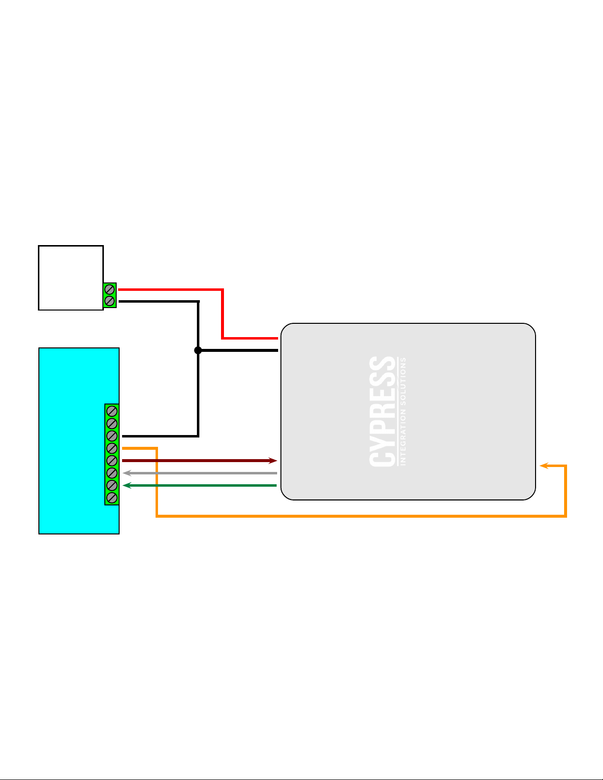
The Handheld Reader is a mobile proximity card reader that connects wirelessly to the access control panel. The Base
Unit connects to the access control panel similar to a standard Wiegand reader and the access control panel validates
the credentials. The Base Unit is able to provide an Access Granted or Access Denied response after a credential is
presented. The Handheld Reader and Base Unit do not store any credential data. There are two types of Single-lane
kits: HHR-4166 (one reader) and HHR-4266 (2 reader).
Advantages of OSDP Secure Channel Protocol
Application Protocol Integrity and Confidentiality Controls: !
OSDP Secure Channel-compliant handheld units and base stations protect the integrity, confidentiality, and
authenticity controls of all messages transmitted across the network.!
Protocol Replay Protection:
Resilient against replay attacks, using a rolling Message Authentication Code to ensure no two messages appear the
same as transmitted over the network, and no two identically received messages are accepted.!
Handheld Reader Authentication State Linked to Authentication Attempt:
No message from the base station (or from an attacker) can cause the user interface to signal authorization without first
having transmitted credential data to the base station. !
Protocol Does Not Leak Sensitive Data:
The OSDP specification relies upon an inherently secure connection to perform initial key exchange, using a default
key defined in the specification. This is done with randomly generated keys, at the the factory. The keys are not stored
by Cypress.!
Authentication Method Diminishes Efficacy of Brute-Force Attack: !
The authentication method implements rate limiting, allowing one attempt per 5 seconds to diminish the efficacy of a
brute-force attack while maintaining system responsiveness during normal use. The base station and handheld unit
firmware do not accept repetitive badge presentations to prevent rogue hardware from searching badge space for
authorized IDs.!
Communication Security Does Not Rely on Protocol Secrecy: !
Implementation of the Security Industry Association’s Open Supervised Device Protocol (OSDP) eliminates the
system’s reliance on protocol secrecy. This protocol is well known and widely accepted in the access control industry
as the solution to data security in physical access control.
HHR-4X66 Single-lane Kits - Overview

Page of5 31
HHR-4X66 Single-lane Kits - Wireless Encryption
OSDP Secure Channel Encryption:!
The HHR-8066 reader has its own OSDP Secure Channel
session with the HHR-8300/HHR-8400 base. Each of
these OSDP Secure Channel sessions is encrypted with
its own encryption key.
Radio Level Encryption:!
The radios in all of the HHR-8066 readers and the
HHR-8300/HHR-8400 base encrypt all of data being
transmitted between the readers and the base. The radio
level encryption uses AES128. The readers and the base
share an encryption key for the radio level encryption.
HHR-8300 /!
HHR-8400 Base
HHR-8066 Readers
HHR-8066 Readers
Arrows show all wireless
devices sharing the same
radio level encryption key.
Arrows show both
readers and the base
have individual OSDP
Secure Channel sessions,
each with their own
encryption key.
HHR-8300 /!
HHR-8400 Base
Wireless Communication
The wireless radios in the HHR-4000 readers and base units use the IEEE 802.15.4 standard for mesh networking. The
HHR readers and base units form ad-hoc mesh networks, which do not require additional external infrastructure (such
as WLAN) to function.!
The communication protocol between HHR-4000 devices over the air is the Open Supervised Device Protocol (OSDP).
OSDP is an IEC standard (IEC 60839-11-5). This protocol uses the AES-128 cipher in CBC mode for both data
confidentiality and message authenticity. !
Wireless Encryption
The HHR-4000 devices wireless communication utilize two layers of encryption. The first layer of encryption is on the
radio link layer, which uses AES-128 to encrypt data packets between the radios in the Handheld readers and the Base
Unit. The second layer of encryption is on the protocol level, which uses the OSDP Secure Channel protocol to encrypt
the OSDP messages sent between the Base Unit and the Handheld Readers.

Page of6 31
Unpacking!
•Remove packaging from units and check interior of Base Unit for any shipping damage.!
•Inventory any included parts (depending on model), shown below.!
•Locate any terminal connectors, manuals / quick-starts, and warranty information.
IMPORTANT SAFETY INSTRUCTIONS AND WARNINGS For LiPo BATTERIES
It is important to specifically use a Lithium Polymer/Li-ion charger only. Do not use a NiMH or NiCd charger. Failure to
use the proper charger may cause a fire, which could result in personal injury/property damage.!
Never charge batteries unattended. When charging LiPo/Li-ion batteries, batteries should constantly be observed to
monitor the charging process to ensure batteries are being charged properly and to respond to potential problems
which may occur.!
Some LiPo/Li-ion chargers on the market may have technical deficiencies and charge the LiPo/Li-ion batteries
incorrectly or at an improper rate. It is your responsibility to ensure the charger you purchased works properly.!
If at any time a battery begins to heat, smoke, swell, or balloon, immediately stop charging the battery and disconnect
the charger, then observe the battery in a safe place for approximately 15 minutes, since the battery could leak and
react with air, causing chemicals to ignite and result in a fire. Since delayed chemical reaction can occur, it is best to
observe the battery as a safety precaution, in a safe area outside of any building or vehicle and away from any
combustible material.
HHR-4X66 Single-lane Kits - Cable Recommendations and Battery Safety
Cable Recommendations
Wiegand / LED
PVC - Belden 9942 or 8777 - 22 AWG 3 Pair Shielded, 250 feet max$
Plenum - Belden 82777 - 22 AWG 3 Pair Shielded, 250 feet max$
PVC - Belden 9873 - 20 AWG 3 Pair Shielded, 500 feet max$
Plenum - Belden 83606 or 85164 - 20 AWG 3 Pair Shielded, 500 feet max
Inputs / Outputs
PVC - Belden 8451 - 22 AWG 1 Pair, 1000 feet max$
Plenum - Belden 82761 - 22 AWG 1 Pair, 1000 feet max
Power
PVC - Belden 8461 - 18 AWG 1 Pair, 25 feet max$
Plenum - Belden 82740 - 18 AWG 1 Pair, 25 feet max

Page of7 31
HHR-4X66 Single-lane Kits - What Is Included In The Kit
HHR-4166!
HHR-8066 Single-lane Reader x1!
HHR-8300 Single-lane Base x1!
HHR-DOCK Charging Dock x1!
HHR-RCHL Wall Plug Charger x1!
This kit has one HHR-8066 reader and the HHR-8300 single-lane base.
HHR-4266!
HHR-8066 Single-lane Reader x2!
HHR-8400 Dual-lane Base x1!
HHR-DOCK Charging Dock x2!
HHR-RCHL Wall Plug Charger x 2!
This kit has two HHR-8066 readers, one set to the IN Lane and the other set to the OUT Lane; and the HHR-8400 dual-
lane base.

Page of8 31
HHR-4X66 Single-lane Kits - HHR-8300 Board A Pin Layout
Board A DIP Switches
Radio Control DIP Switches
J1 Header
J2 Header
J3 Header
Status/Diagnostic LED
1 8 - 16VDC
2 Ground
Status LED
1 EXP(+)
2 EXP(-)
3 +5V Out
4 P.R. 2
5 P.R. 1
6 LED In
7 D1/D Out
8 D0/C Out
Relay 4 N.O. 1
Relay 4 COM 2
Relay 4 N.C. 3
Relay 3 N.O. 4
Relay 3 COM 5
Realy 3 N.C. 6
Ground 7
Aux Out 8
Relay 2 In 9
Relay 1 In 10
Suprex®
Central
Board A

Page of9 31
HHR-4X66 Single-lane Kits - HHR-8400 Board A and Board B Pin Layout
1 8 - 16VDC
2 Ground
Status LED
1 EXP(+)
2 EXP(-)
3 +5V Out
4 P.R. 2
5 P.R. 1
6 LED In
7 D1/D Out
8 D0/C Out
Relay 4 N.O. 1
Relay 4 COM 2
Relay 4 N.C. 3
Relay 3 N.O. 4
Relay 3 COM 5
Realy 3 N.C. 6
Ground 7
Aux Out 8
Relay 2 In 9
Relay 1 In 10
Suprex®
Central
1 8 - 16VDC
2 Ground
Status LED
1 EXP(+)
2 EXP(-)
3 +5V Out
4 P.R. 2
5 P.R. 1
6 LED In
7 D1/D Out
8 D0/C Out
Relay 4 N.O. 1
Relay 4 COM 2
Relay 4 N.C. 3
Relay 3 N.O. 4
Relay 3 COM 5
Realy 3 N.C. 6
RS-232 TxD 7
RS-232 RxD 8
Ground 9
Aux Out 10
Relay 2 In 11
Relay 1 In 12
Suprex®
EXP Central
Board A
Board B
J1 Header
Board B DIP Switches
J2 Header
J3 Header
Board A DIP Switches
Radio Control DIP Switches
J1 Header
J2 Header
J3 Header
Status/Diagnostic LED

Page of10 31
HHR-4X66 Single-lane Kits - HHR-8300 Wiring Diagram
DC Power
Supply
Power
Ground
Access
Control
Panel
N.O.
COM
Ground
LED 2 Out
LED 1 Out
Data 1
Data 0
1 8 - 16VDC
2 Ground
Status LED
1 EXP(+)
2 EXP(-)
3 +5V Out
4 P.R. 2
5 P.R. 1
6 LED In
7 D1/D Out
8 D0/C Out
Relay 4 N.O. 1
Relay 4 COM 2
Relay 4 N.C. 3
Relay 3 N.O. 4
Relay 3 COM 5
Realy 3 N.C. 6
Ground 7
Aux Out 8
Relay 2 In 9
Relay 1 In 10
Suprex®
Central
Board A

Page of11 31
HHR-4X66 Single-lane Kits - HHR-8400 Wiring Diagram
DC Power
Supply
Power
Ground
Access
Control
Panel
BOARD A
BOARD B
Ground
LED 2 Out
LED 1 Out
Data 1
COM
N.O.
Data 1
LED 1 Out
LED 2 Out
Ground
COM
N.O.
Port 1
Port 2
1 8 - 16VDC
2 Ground
Status LED
1 EXP(+)
2 EXP(-)
3 +5V Out
4 P.R. 2
5 P.R. 1
6 LED In
7 D1/D Out
8 D0/C Out
Relay 4 N.O. 1
Relay 4 COM 2
Relay 4 N.C. 3
Relay 3 N.O. 4
Relay 3 COM 5
Realy 3 N.C. 6
RS-232 TxD 7
RS-232 RxD 8
Ground 9
Aux Out 10
Relay 2 In 11
Relay 1 In 12
Suprex®
EXP Central
1 8 - 16VDC
2 Ground
Status LED
1 EXP(+)
2 EXP(-)
3 +5V Out
4 P.R. 2
5 P.R. 1
6 LED In
7 D1/D Out
8 D0/C Out
Relay 4 N.O. 1
Relay 4 COM 2
Relay 4 N.C. 3
Relay 3 N.O. 4
Relay 3 COM 5
Realy 3 N.C. 6
Ground 7
Aux Out 8
Relay 2 In 9
Relay 1 In 10
Suprex®
Central
Data 0
Data 0

Page of12 31
HHR-4X66 Single-lane Kits - LED Functions
HHR-8066-GY Single-lane Reader
Red LED
Green LED
Blue LED
Handheld Reader LED Functions
•Red LED (top left - access denied) !
•Flashing red indicates access denied (negative acknowledge)!
•Blue LED (top center - power & communication status) !
•Solid blue indicates that the HHR reader is powered on and is not communicating with the HHR base. !
•Flashing blue indicates that the HHR reader is communicating with the HHR base. !
•Green LED (top right - access granted)!
•Flashing green indicates access granted (positive acknowledge).!
•Red LED and Green LED (credential read indicator)!
•Red and Green LEDs flashing once indicates that a credential has been read by the HHR reader. !
Base Unit Diagnostic LED Functions
Board A and Board B each have a diagnostic LED. These diagnostic LEDs are located between the 2-pin and 8-pin
headers on each board, see pg. 8.!
The diagnostic LEDs are bi-color and may display red, green, or red and green, depending on the status.!
•The Board A diagnostic LED will flash green when it is powered on. This is the only state for the Board A diagnostic
LED. !
•The Board B diagnostic LED will be solid red when if it is powered on and not connected to Board A.!
•The Board B diagnostic LED will be solid green when it is powered on and connected to Board A.

Page of13 31
HHR-4X66 Single-lane Kits - Button Functions
Handheld Reader Button Functions
•Power Button: When pressed, this button will power the handheld reader on or off. This button is a non-tactile
button. The Red LED (top left) will be solid red when the Handheld Reader is powered on.!
•Vend Button: Allows the user to operate a door, or a gate, or other equipment in the area. This needs to be
configured by the installer. When pressed, Relay 3 on the Base Unit will be activated for as long as the button is
held. !
•The Vend button on the IN Reader controls Relay 3 on Board A.!
•The Vend button on the OUT Reader controls Relay 3 on Board B.!
HHR-8066-GY Single-lane Reader
Vend Button
Power Button

Page of14 31
HHR-4X66 Single-lane Kits - Reading Credentials
Reading Credentials
To read a credential, present it to the read
area around the “bullseye” on the face of
the reader. !
Credential Read Area!
When the credential is read by the
HHR-8066 the red and green LEDs will flash
once and the reader will emit a medium
pitch beep.!
When the HHR-8066 reader is
communicating with the Base Unit
(indicated by the flashing blue LED) the
credential data will be transmitted to the
access controller from the Base Unit.!
If the HHR-8066 reader is not
communicating with the (indicated by the
solid blue LED) no credential data will be
transmitted to the access controller from the
Base Unit. !
RFID Card

Page of15 31
Access Granted Response!
The Access Granted Response is controlled by the LED In
pin on the Base Unit. When the LED In pin is an active low
digital input. Its normal state is 5V and its active state is 0V.
There is a 5 second window after a credential has been read
by the reader that the Access Granted Response signal is
acknowledged by the HHR reader. Otherwise, the state of
the LED In pin will be ignored by the HHR reader. !
After a credential has been read by the HHR reader and the
LED In pin has been activated by the access controller; the
green LED will flash, the reader will vibrate, and will emit a
high pitched beep. The Access Granted Response will last
for as long as the LED In is activated. !
There are two LED In pins, one on Board A and one on
Board B. The LED In pin on Board A controls the Access
Granted Response while the HHR reader is set to IN Mode.
The LED In pin on Board B controls the Access Granted
Response while the HHR reader is set to OUT Mode.
Access Denied Response
The Access Denied Response is controlled by the Relay 1 In
pin on the Base Unit. When the Relay 1 In pin is an active
low digital input. Its normal state is 5V and its active state is
0V. There is a 5 second window after a credential has been
read by the reader that the Access Denied Response signal
is acknowledged by the HHR reader. Otherwise, the state of
the Relay 1 In pin will be ignored but the HHR reader.!
After a credential has been read by the HHR reader and the
Relay 1 In pin has been activated by the access controller;
the red LED will flash, the reader will vibrate in a pulsing
pattern, and emit a low pitched beep. The Access Denied
Response will last for as long as the Relay 1 In pin is
activated.!
There are two Relay 1 In pins, one on Board A and one on
Board B. The Relay 1 In pin on Board A controls the Access
Denied Response while the HHR reader is set to IN Mode.
The Relay 1 In pin on Board B controls the Access Denied
Response while the HHR reader is set to OUT Mode.
HHR-4X66 Single-lane Kits - Access Granted / Access Denied Responses

Page of16 31
HHR-4X66 Single-lane Kits - Using the Vend Button
The Vend button on the IN Reader is used to operate Relay 3 on Board A while the Vend button on the OUT Reader is
used to operate Relay 3 on Board B. Common applications for the Vend Button are allowing the Reader operator to
manually open a gate or trigger a duress alarm. !
Relay 3 on both Board A and Board B is a dry contact output by default. Power can be run through this relay if
required, however, this relay rated for a max of 30 VDC at 1 amp. More detailed relay specifications can be found in the
Specifications table on pg. 2. !
Below are diagrams that show how Relay 3 changes state when the Vend button is pressed.
The diagram to the right
shows the IN Reader. The
Vend button is not being
pressed and the state of
Relay 3 on Board A is
normal (continuity between
Relay 3 Com and Relay 3
N.C.).
In this diagram, the Vend
button on the IN Reader is
being pressed. The state of
Relay 3 on Board A is active
(continuity between Relay 3
Com and Relay 3 N.O.).
1 8 - 16VDC
2 Ground
Status LED
1 EXP(+)
2 EXP(-)
3 +5V Out
4 P.R. 2
5 P.R. 1
6 LED In
7 D1/D Out
8 D0/C Out
Relay 4 N.O. 1
Relay 4 COM 2
Relay 4 N.C. 3
Relay 3 N.O. 4
Relay 3 COM 5
Realy 3 N.C. 6
Ground 7
Aux Out 8
Relay 2 In 9
Relay 1 In 10
Suprex®
Central
1 8 - 16VDC
2 Ground
Status LED
1 EXP(+)
2 EXP(-)
3 +5V Out
4 P.R. 2
5 P.R. 1
6 LED In
7 D1/D Out
8 D0/C Out
Relay 4 N.O. 1
Relay 4 COM 2
Relay 4 N.C. 3
Relay 3 N.O. 4
Relay 3 COM 5
Realy 3 N.C. 6
Ground 7
Aux Out 8
Relay 2 In 9
Relay 1 In 10
Suprex®
Central
1 8 - 16VDC
2 Ground
Status LED
1 EXP(+)
2 EXP(-)
3 +5V Out
4 P.R. 2
5 P.R. 1
6 LED In
7 D1/D Out
8 D0/C Out
Relay 4 N.O. 1
Relay 4 COM 2
Relay 4 N.C. 3
Relay 3 N.O. 4
Relay 3 COM 5
Realy 3 N.C. 6
RS-232 TxD 7
RS-232 RxD 8
Ground 9
Aux Out 10
Relay 2 In 11
Relay 1 In 12
Suprex®
EXP Central
1 8 - 16VDC
2 Ground
Status LED
1 EXP(+)
2 EXP(-)
3 +5V Out
4 P.R. 2
5 P.R. 1
6 LED In
7 D1/D Out
8 D0/C Out
Relay 4 N.O. 1
Relay 4 COM 2
Relay 4 N.C. 3
Relay 3 N.O. 4
Relay 3 COM 5
Realy 3 N.C. 6
RS-232 TxD 7
RS-232 RxD 8
Ground 9
Aux Out 10
Relay 2 In 11
Relay 1 In 12
Suprex®
EXP Central
Board A
Board B
Board B
Board A

Page of17 31
HHR-4X66 Single-lane Kits - Using the Vend Button (continued)
The diagram to the right
shows OUT Reader. The
Vend button is not being
pressed and the state of
Relay 3 on Board B is
normal (continuity between
Relay 3 Com and Relay 3
N.C.).
In this diagram, the Vend
button on the OUT Reader
is being pressed. The state
of Relay 3 on Board B is
active (continuity between
Relay 3 Com and Relay 3
N.O.).
1 8 - 16VDC
2 Ground
Status LED
1 EXP(+)
2 EXP(-)
3 +5V Out
4 P.R. 2
5 P.R. 1
6 LED In
7 D1/D Out
8 D0/C Out
Relay 4 N.O. 1
Relay 4 COM 2
Relay 4 N.C. 3
Relay 3 N.O. 4
Relay 3 COM 5
Realy 3 N.C. 6
Ground 7
Aux Out 8
Relay 2 In 9
Relay 1 In 10
Suprex®
Central
1 8 - 16VDC
2 Ground
Status LED
1 EXP(+)
2 EXP(-)
3 +5V Out
4 P.R. 2
5 P.R. 1
6 LED In
7 D1/D Out
8 D0/C Out
Relay 4 N.O. 1
Relay 4 COM 2
Relay 4 N.C. 3
Relay 3 N.O. 4
Relay 3 COM 5
Realy 3 N.C. 6
RS-232 TxD 7
RS-232 RxD 8
Ground 9
Aux Out 10
Relay 2 In 11
Relay 1 In 12
Suprex®
EXP Central
1 8 - 16VDC
2 Ground
Status LED
1 EXP(+)
2 EXP(-)
3 +5V Out
4 P.R. 2
5 P.R. 1
6 LED In
7 D1/D Out
8 D0/C Out
Relay 4 N.O. 1
Relay 4 COM 2
Relay 4 N.C. 3
Relay 3 N.O. 4
Relay 3 COM 5
Realy 3 N.C. 6
Ground 7
Aux Out 8
Relay 2 In 9
Relay 1 In 10
Suprex®
Central
1 8 - 16VDC
2 Ground
Status LED
1 EXP(+)
2 EXP(-)
3 +5V Out
4 P.R. 2
5 P.R. 1
6 LED In
7 D1/D Out
8 D0/C Out
Relay 4 N.O. 1
Relay 4 COM 2
Relay 4 N.C. 3
Relay 3 N.O. 4
Relay 3 COM 5
Realy 3 N.C. 6
RS-232 TxD 7
RS-232 RxD 8
Ground 9
Aux Out 10
Relay 2 In 11
Relay 1 In 12
Suprex®
EXP Central
Board A
Board A
Board B
Board B

Page of18 31
HHR-4X66 Single-lane Kits - HHR-4166 Bench Testing
Bench Test Setup!
1. Before installing the Base Unit and Handheld Reader in the field, they should be tested at a convenient bench top
location. This will make it easier to troubleshoot potential issues. !
2. The Base Unit and Handheld Reader should be at least 24 inches apart during bench testing.!
3. Connect the Base Unit to the access controller and follow the steps below.!
4. To connect the Base Unit to the access controller, 1 Wiegand port must be available.!
5. Connecting Board A to the access controller:!
A. Wiegand Data: Connect Data 0, Data 1, and a common ground to the one Wiegand port on the access
controller. !
B. Access Granted Response: Connect an active low digital output to the LED In pin. Alternatively, a dry contact
can be connected to the LED In pin and Ground. Make sure the output connected to the LED In pin is
configured to activate for at least one second when a valid credential is received on this Wiegand port. !
C. Access Denied Response: Connect an active low digital output to the Relay 1 In pin. Alternatively, a dry contact
can be connected to the Relay 1 In pin and Ground. Make sure the output connected to the Relay 1 In pin is
configured to activate for at least one second when an invalid credential is received on this Wiegand port.!
D. Vend Feature: Connect Relay 3 COM and Relay 3 N.O. (normally open) to the access controller. This relay
output can be used to control a door, a gate, or other equipment.!
6. Use a power supply that can supply 8-16Vdc @ 300mA. Connect the power supply to the Board A in the
HHR-8300.!
Bench Testing Steps!
1. Power on the reader. The blue LED will be on and solid when the reader is powered on. The blue LED will changed
to flashing when the reader is communicating with the Base Unit. !
2. Present a valid credential to the reader. The red and green LEDs will flash once, indicating the credential has been
read. Verify that the access controller has received the read on the Wiegand port Board A is connected to. Observe
the Access Granted Response; the green LED will be flashing, the reader will vibrate, and the reader will emit a high
pitched tone. The Access Granted Response will last as long as the LED In pin on Board A is activated. !
3. Present an invalid credential to the reader. The red and green LEDs will flash once, indicating the credential has
been read. Verify that the access controller has received the read on the Wiegand port Board A is connected to.
Observe the Access Denied Response; the red LED will be flashing, the reader will vibrate in a pulsing pattern, and
the reader will emit a low pitched tone. The Access Denied Response will last as long as the Relay 1 In pin on Board
A is activated. !
4. Press and release the Vend button. Verify that Relay 3 on Board A has changed state. Observe that the duress
alarm activates, the door/gate opens, etc. A volt meter in continuity mode can also be used determine the state of
the relay. When the Vend Button is pressed, there will be continuity between Relay 3 COM and Relay 3 N.O. for as
long as the Vend Button is held down.!
5. Once the HHR Base Unit and Reader(s) have passed these bench testing steps, the components are ready to be
installed in the field.

Page of19 31
HHR-4X66 Single-lane Kits - HHR-4266 Bench Test Setup
Bench Test Setup!
1. Before installing the Base Unit and Handheld Reader in the field, they should be tested at a convenient bench top
location. This will make it easier to troubleshoot potential issues. !
2. The Base Unit and Handheld Reader should be at least 24 inches apart during bench testing.!
3. Connect the Base Unit to the access controller and follow the steps below.!
4. To connect the Base Unit to the access controller, 2 separate Wiegand ports must be available.!
5. Connecting Board A to the access controller:!
A. Wiegand Data: Connect Data 0, Data 1, and a common ground to the one Wiegand port on the access
controller. !
B. Access Granted Response: Connect an active low digital output to the LED In pin. Alternatively, a dry contact
can be connected to the LED In pin and Ground. Make sure the output connected to the LED In pin is
configured to activate for at least one second when a valid credential is received on this Wiegand port. !
C. Access Denied Response: Connect an active low digital output to the Relay 1 In pin. Alternatively, a dry contact
can be connected to the Relay 1 In pin and Ground. Make sure the output connected to the Relay 1 In pin is
configured to activate for at least one second when an invalid credential is received on this Wiegand port.!
D. Vend Feature: Connect Relay 3 COM and Relay 3 N.O. (normally open) to the access controller. This relay
output can be used to control a door, a gate, or other equipment.!
6. Connecting Board B to the access controller:!
A. Wiegand Data: connect Data 0, Data 1, and a common ground to another Wiegand port on the access
controller. !
B. Access Granted Response: connect an active low digital output to the LED In pin. Alternatively, a dry contact
can be connected to the LED In pin and Ground. Make sure the output connected to the LED In pin is
configured to activate for at least one second when a valid credential is received on this Wiegand port. !
C. Access Denied Response: Connect an active low digital output to the Relay 1 In pin. Alternatively, a dry contact
can be connected to the Relay 1 In pin and Ground. Make sure the output connected to the Relay 1 In pin is
configured to activate for at least one second when an invalid credential is received on this Wiegand port.!
D. Vend Feature: connect Relay 3 COM and Relay 3 N.O. (normally open) to the access controller. This relay output
can be used to control a door, a gate, or other equipment.!
7. Board A and Board B need to be connected. Connect EXP(+) on Board A to EXP(+) on Board B. Connect EXP(-) on
Board A to EXP(-) to Board B. !
8. Use a power supply that can supply 8-16Vdc @ 600mA. Both Board A and Board B need to have a power
connection, and each require 300 mA.

Page of20 31
Bench Testing Steps
The HHR-4266 kit has two readers, go through steps 1-8 for each reader. One reader is set to IN mode and the other
reader is set to OUT mode. The reader set to IN mode is controlled by Board A, the reader set to OUT mode is
controlled by Board B. Typically, the reader serial numbers are sequential. The reader will the lower serial number is set
to IN mode, and the reader with the higher serial number is set to OUT mode. !
1. Power on the IN reader. The blue LED will be on and solid when the reader is powered on. The blue LED will
changed to flashing when the reader is communicating with the Base Unit. !
2. Present a valid credential to the reader. The red and green LEDs will flash once, indicating the credential has been
read. Verify that the access controller has received the read on the Wiegand port Board A is connected to. Observe
the Access Granted Response; the green LED will be flashing, the reader will vibrate, and the reader will emit a high
pitched tone. The Access Granted Response will last as long as the LED In pin on Board A is activated. !
3. Present an invalid credential to the reader. The red and green LEDs will flash once, indicating the credential has
been read. Verify that the access controller has received the read on the Wiegand port Board A is connected to.
Observe the Access Denied Response; the red LED will be flashing, the reader will vibrate in a pulsing pattern, and
the reader will emit a low pitched tone. The Access Denied Response will last as long as the Relay 1 In pin on Board
A is activated. !
4. Press and release the Vend button. Verify that Relay 3 on Board A has changed state. Observe that the duress
alarm activates, the door/gate opens, etc. A volt meter in continuity mode can also be used determine the state of
the relay. When the Vend Button is pressed, there will be continuity between Relay 3 COM and Relay 3 N.O. for as
long as the Vend Button is held down.!
5. Power on the OUT reader. The blue LED should still be flashing, indicating the reader is communicating with the
Base Unit.!
6. Present a valid credential to the reader. The red and green LEDs will flash once, indicating the credential has been
read. Verify that the access controller has received the read on the Wiegand port Board B is connected to. Observe
the Access Granted Response; the green LED will be flashing, the reader will vibrate, and the reader will emit a high
pitched tone. The Access Granted Response will last as long as the LED In pin on Board B is activated.!
7. Present an invalid credential to the reader. The red and green LEDs will flash once, indicating the credential has
been read. Verify that the access controller has received the read on the Wiegand port Board B is connected to.
Observe the Access Denied Response; the red LED will be flashing, the reader will vibrate in a pulsing pattern, and
the reader will emit a low pitched tone. The Access Denied Response will last as long as the Relay 1 In pin on Board
B is activated.!
8. Press and release the Vend button. Verify that Relay 3 on the Board B has changed state. Observe that the duress
alarm activates, the door, gate, or other equipment. A volt meter in continuity mode can also be used determine the
state of the relay. When the Vend Button is pressed, there will be continuity between Relay 3 COM and Relay 3 N.O.
for as long as the Vend Button is held down.!
9. Once the HHR Base Unit and readers have passed these bench testing steps, the components are ready to be
installed in the field.
HHR-4X66 Single-lane Kits - HHR-4266 Bench Testing
This manual suits for next models
4
Table of contents
Popular Spreader manuals by other brands

Field Tuff
Field Tuff AS-125ATV12 manual

Precision Products
Precision Products SB4300RD Parts list and instructions

Precision
Precision DS1000D Instructions-parts list

Gearmore
Gearmore PTB560 Operation, service & parts manual

Broadwood
Broadwood Wessex Country FS170T Operations manual and parts book

SnowEx
SnowEx V-Maxx G2 owner's manual

Neilsen
Neilsen CT2214 Original manual

Redexim
Redexim RINK 1005 Operating and parts manual

Western
Western PRO-FLO 300W Owner's manual and installation instructions

Agri-Fab
Agri-Fab 45-03295 owner's manual

Chapin
Chapin 80008N Assembly / operation instructions / parts

Agri-Fab
Agri-Fab 45-03121 owner's manual