Chicago Dryer Edge MAXX User manual


©Chicago Dryer Company
Instruction Manual #3018-0032E
CHICAGO DRYER COMPANY
2200 N. Pulaski, Chicago, Illinois USA 60639-3737
Telephone: (773) 235-4430 Fax: (773) 235-4439 www.chidry.com

Edge MAXX Table of Contents
i
TABLE OF CONTENTS
MANUAL
Chapter 1-Introduction
Chapter 2-Installation
Chapter 3-Operating Guidelines
Chapter 4-Preventive Maintenance
Chapter 5-Operating Principles
Chapter 6-Troubleshooting
Chapter 7-Repair
CHI PANEL BULLETIN
PICTURE PARTS LIST
SCHEMATIC PARTS LIST
APPENDIX
Floor Plans
Technical Specifications
Torque Specifications
INDEX
TOC
INDEX

Table of Contents Edge MAXX
ii
CHAPTER 1 INTRODUCTION
1.1 Warranty .................................................................................................. 1-2
1.2 Scope of Manual ..................................................................................... 1-2
1.3 Safety ...................................................................................................... 1-3
Safe Work Habits .................................................................................... 1-3
Safety Features ....................................................................................... 1-4
1.4 Equipment Description ............................................................................ 1-6
Machine Widths ....................................................................................... 1-6
Optional Equipment ................................................................................. 1-6
TOC
INDEX

Edge MAXX Table of Contents
iii
CHAPTER 2 INSTALLATION
2.1 Site and Utility Requirements .................................................................. 2-2
2.2 Installation Procedures ............................................................................ 2-3
Inspection ................................................................................................ 2-3
Uncrating and General Placement .......................................................... 2-4
Input Conveyor Installation ...................................................................... 2-4
Compressed Air Supply Connection ....................................................... 2-6
Final Positioning/Easi-Glide Preparation (Option) ................................... 2-7
Reject Conveyor Positioning ................................................................... 2-8
Electrical Connection .............................................................................. 2-9
2.3 Pre-Operational Checkout ..................................................................... 2-14
Final Protective Wrapper Removal ........................................................ 2-14
Security of Hardware ............................................................................. 2-14
Clean the Corner Photosensors ............................................................ 2-15
Compressed Air Supply Checkout ........................................................ 2-15
Safety Device and CHI Panel Function Checkout ................................. 2-17
Spread/Feed Function Check ............................................................... 2-19
Easi-Glide Checkout (Option) ............................................................... 2-21
Checkout Completion ............................................................................ 2-22
Cleaning the Unit ................................................................................... 2-22
TOC
INDEX

Table of Contents Edge MAXX
iv
CHAPTER 3 OPERATING GUIDELINES
3.1 Safety Features ....................................................................................... 3-2
Main Disconnect Switch .......................................................................... 3-2
Safety STOP Buttons .............................................................................. 3-2
Safety Sensors and Guards .................................................................... 3-2
Safety Interlock Switches ........................................................................ 3-3
Safety Labels .......................................................................................... 3-3
3.2 Operating Controls .................................................................................. 3-4
Front Controls.......................................................................................... 3-4
Right Rear Controls ................................................................................. 3-6
CHI Panel Controls and Indicators .......................................................... 3-7
3.3 Daily Operating Procedures .................................................................... 3-8
Start-Up ................................................................................................... 3-8
Interconnected Stop Circuit (option) Operation Notes .......................... 3-10
Flatwork Handling ................................................................................. 3-10
Handling Jams and Misfeeds Safely ..................................................... 3-14
Shut-Down ............................................................................................ 3-15
3.4 Operating Techniques ........................................................................... 3-15
Maximum Efficiency .............................................................................. 3-15
Maximum Feeding Speed ..................................................................... 3-16
Gap Buster Feature ............................................................................... 3-16
TOC
INDEX

Edge MAXX Table of Contents
v
CHAPTER 4 PREVENTIVE MAINTENANCE
4.1 Daily PM (8 hours) ................................................................................... 4-2
Watch and Listen for Anything Abnormal ................................................ 4-2
General Cleanliness ................................................................................ 4-2
Check Safety Equipment ......................................................................... 4-3
4.2 Weekly PM (50 hours) ............................................................................. 4-3
Check and Clean Photosensors and Reflectors ..................................... 4-4
Check and Clean Inverters ...................................................................... 4-4
Check For String Accumulation ............................................................... 4-5
Check Pneumatic Clutch/Brake Roller Alignment ................................... 4-5
Lubricate Transfer and Upper Spreader Rails ......................................... 4-6
Check Transfer Clamp Assembly and Grooved Bearings ....................... 4-7
Inspect the Rodless Air Cylinders ........................................................... 4-7
Inspect Air Filter/Auto Drain .................................................................... 4-9
Check Air Pressure Settings ................................................................... 4-9
Check Belt and Ribbon Condition and Tension ......................................4-11
4.3 Monthly PM (200 hours) .........................................................................4-11
Check Setscrews................................................................................... 4-12
Check Spreader Clamp Linear Bearing Assemblies ............................. 4-12
Check Upper and Lower Spreader Belt Condition and Tension ............ 4-13
Check Transfer Belts Condition and Tension ........................................ 4-13
Inspect Drive Belt Condition .................................................................. 4-14
Clean and Lubricate Drive Chain .......................................................... 4-15
4.4 Semi-Annual PM (1000 hours) .............................................................. 4-15
Clean Air Filter/ Auto Drain .................................................................... 4-16
Check and Grease Bearings ................................................................. 4-17
Check and Grease Transfer Conveyor Gears ....................................... 4-19
4.5 Annual PM (2000 hours) ....................................................................... 4-19
Check All Electrical Connections ........................................................... 4-20
Check Insulation Resistance to Earth Ground ...................................... 4-20
TOC
INDEX

Table of Contents Edge MAXX
vi
CHAPTER 5 OPERATING PRINCIPLES
Safety ................................................................................................................ 5-2
5.1 Electrical System ..................................................................................... 5-2
Power System ......................................................................................... 5-2
Control System ........................................................................................ 5-7
5.2 Compressed Air System ........................................................................ 5-14
Air Filter/Regulators............................................................................... 5-14
Air Pressure Switch ............................................................................... 5-14
Air Reservoir .......................................................................................... 5-15
Air Valves/Air Valve Solenoids .............................................................. 5-15
Air Cylinders .......................................................................................... 5-15
Flow Controls ........................................................................................ 5-15
Air Bars .................................................................................................. 5-15
Pneumatic Clutch/Brake ........................................................................ 5-15
5.3 Mechanical System ............................................................................... 5-16
Inlet Drive System ................................................................................. 5-16
Transfer Drive System ........................................................................... 5-17
Spread Drive Systems .......................................................................... 5-18
Discharge Drive System ........................................................................ 5-19
Reject Drive Systems ............................................................................ 5-20
5.4 Sequence of Operation ......................................................................... 5-21
Stand-by Phase ..................................................................................... 5-22
Start-up Phase ...................................................................................... 5-22
Input Phase ........................................................................................... 5-23
Transfer Phrase ..................................................................................... 5-23
Spread Phase ....................................................................................... 5-24
Discharge Phase ................................................................................... 5-25
Reject Phase ......................................................................................... 5-25
Error Conditions .................................................................................... 5-25
TOC
INDEX

Edge MAXX Table of Contents
vii
CHAPTER 6 TROUBLESHOOTING
Troubleshooting Symptoms ............................................................................... 6-2
6.1 CHI Diagnostic Message Index ............................................................... 6-6
6.2 LED Diagnostics ...................................................................................... 6-8
6.3 Electrical .................................................................................................. 6-9
6.4 Mechanical ............................................................................................ 6-13
6.5 Inlet Section .......................................................................................... 6-14
6.6 Transfer Section .................................................................................... 6-16
6.7 Spread Section ...................................................................................... 6-19
6.8 Discharge Section ................................................................................. 6-23
6.9 Reject Section ....................................................................................... 6-25
6.10 Sensor Function .................................................................................... 6-26
6.11 CHI Panel .............................................................................................. 6-27
6.12 Compressed Air System ........................................................................ 6-28
TOC
INDEX

Table of Contents Edge MAXX
viii
Repair topics continued on the next page...
CHAPTER 7 REPAIR
7.1 Safety Considerations ............................................................................. 7-2
7.2 Parts Availability ...................................................................................... 7-3
7.3 Inlet Section ............................................................................................ 7-3
Inlet Conveyor Lift Cylinder Bracket Adjustment ..................................... 7-4
Inlet Conveyor Belt Replacement ............................................................ 7-5
Inlet Conveyor Drive Belt Tension Adjustment ........................................ 7-6
Pneumatic Clutch/Brake Roller Alignment .............................................. 7-7
Pneumatic Clutch/Brake Roller Drive Belt Tension Adjustment ............... 7-8
7.4 Transfer Section ...................................................................................... 7-9
Transfer Clamp Check and Adjustment ................................................. 7-10
Transfer Clamp Assembly Replacement ............................................... 7-12
Transfer Clamp Eccentric Grooved Bearing Tension Adjustment ......... 7-13
Transfer Clamp Grooved Bearing Replacement ................................... 7-14
Transfer Belt Tension Adjustment .......................................................... 7-15
Transfer Belt Replacement .................................................................... 7-16
7.5 Spread Section ...................................................................................... 7-17
Spreader Clamp Mechanical Adjustment .............................................. 7-17
Upper Spreader Belt Tension Adjustment ............................................. 7-18
Upper Spreader Belt Replacement ....................................................... 7-18
Upper Spreader Clamp Grooved Bearing Replacement ....................... 7-20
Lower Spreader Drive Belt Tension Adjustment .................................... 7-21
Lower Spreader Drive Belt Replacement .............................................. 7-22
Lower Spreader Belt Tension Check/Replacement ............................... 7-22
Lower Spreader Belt Gap Adjustment ................................................... 7-23
TOC
INDEX

Edge MAXX Table of Contents
ix
7.6 Discharge Section ................................................................................. 7-25
Discharge Conveyor Ribbons Tension Adjustment ............................... 7-26
Discharge Conveyor Ribbons Replacement ......................................... 7-26
Discharge Conveyor Guide Ribbons Tension Adjustment/Replacement ......
7-28
Discharge Conveyor Drive Belt Tension Adjustment ............................. 7-29
Discharge Conveyor Drive Roll Tracking Tape Replacement ................ 7-29
Discharge Conveyor Doffer Roll Pressure Adjustment .......................... 7-30
Discharge Conveyor Doffer Roll Cover Replacement ........................... 7-31
7.7 Reject Section ....................................................................................... 7-33
Transfer Conveyor Drive Belt Tension Adjustment ................................ 7-33
Transfer Conveyor Ribbon Tension Adjustment/Replacement .............. 7-34
Transfer Conveyor Drive and Idler Roll Tracking Tap Replacement ..... 7-35
Side Conveyor Drive Belt Tension Adjustment ...................................... 7-36
Side Conveyor Belt Replacement/Tension Spring Check/Replacement 7-37
Reject Conveyor Drive Belt Tension Adjustment ................................... 7-39
Reject Conveyor Ribbon Tension Adjustment/Replacement ................. 7-40
Reject Conveyor Drive and Idler Roll Tracking Tape Replacement ....... 7-41
7.8 Sensors ................................................................................................. 7-42
General Photosensor Alignment ........................................................... 7-42
Exit/Gap Photosensor Alignment .......................................................... 7-43
Photosensor Replacement .................................................................... 7-43
General Photosensor Sensitivity Adjustment ........................................ 7-45
Wall Photosensor Sensitivity Adjustment .............................................. 7-46
Proximity Sensor Positioning Adjustment .............................................. 7-47
Proximity Sensor Replacement ............................................................. 7-50
7.9 Compressed Air System ........................................................................ 7-51
Air Cylinder Air Flow Adjustment ........................................................... 7-51
Discharge Conveyor Air Cylinder Air Flow Adjustment .......................... 7-53
Spreader Clamp Back Air Pressure Adjustment .................................... 7-54
Inlet Transfer Rodless Air Cylinder Service ........................................... 7-55
Air Bar Alignment .................................................................................. 7-61
Air Foil Adjustment ................................................................................ 7-62
Tail Air Assembly Adjustment ................................................................ 7-63
TOC
INDEX

Edge MAXX Introduction
1-1
Chapter 1
INTRODUCTION
This chapter contains the following sections:
1.1 Warranty
1.2 Scope of Manual
1.3 Safety
1.4 Equipment Description
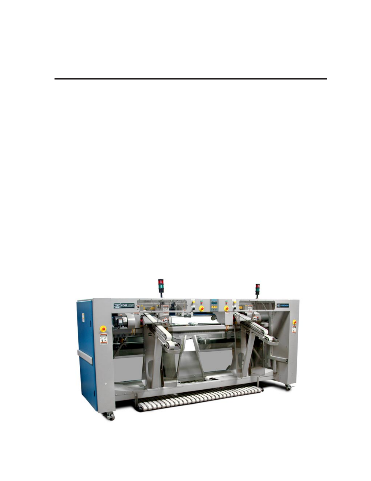
The Edge Maxx® automatic spreader/feeders allow operators to feed wet sheets or other large pieces
of flatwork into a flatwork ironer. Because operators do not need to locate and clip one or more corners
during loading, each operator can feed substantially more pieces per hour than using a traditional automatic
feeder. The unit has two operator stations for higher production rates.
Like the rest of the CHICAGO® product line, the Edge Maxx is designed, manufactured, and assembled
in Chicago, Illinois. Before the CHICAGO® nameplate is affixed to any machine, a final inspection is
performed, including thorough testing under load conditions.
Any questions concerning the installation, operation, or repair of the unit should be directed to a local
authorized CHICAGO® dealer or the Chicago Dryer Company factory Service Department at:
Chicago Dryer Company (773) 235-4430
2200 North Pulaski Fax (773) 235-4439
Chicago, Illinois USA 60639-3737 Email service@chidry.com
Figure 1-1: The Edge Maxx provides high quality spreading and feeding.
TOC
INDEX

Introduction Edge MAXX
1-2
1.1 Warranty
A full page warranty statement is located at
the front of this instruction manual. Please take
the time to review this warranty and understand
its provisions.
1.2 Scope of Manual
This instruction manual will help you keep
your CHICAGO® product operating safely,
efficiently and with minimum expense. Individual
chapters in this manual provide the necessary
information required for safe installation,
operation, maintenance, troubleshooting, and
repair of the unit.
Updates
Occasionally, new information about the
unit becomes available after publication of this
manual. If you receive a CHICAGO®
FYI Service
Bulletin pertaining to our unit, insert the bulletin
in the front of the manual.
Chapter 1 - Introduction
Provides overviews of: the unit and its key
features, this manual, and important safety
features.
Chapter 2 - Installation
Describes recommended procedures for
determining a suitable location for the unit and
connecting the electrical and the compressed air
supplies. This chapter also includes checkout
procedures to ensure all systems are working
properly. Local requirements often vary, so follow
local codes at all times.
Chapter 3 - Operating Guidelines
Gives recommendations for operating the unit
at maximum efficiency. This chapter also includes
instructions for the operators and suggestions for
work organization.
Chapter 4 - Preventive Maintenance
Contains procedures for Daily, Weekly,
Monthly, Semi-Annual, and Annual
maintenance. Follow these procedures to keep the
unit operating safely and at maximum efficiency.
A Preventive Maintenance schedule is located at
the front of the chapter.
Chapter 5 - Operating Principles
Describes the operation of the unit in detail. A
good understanding of this chapter will help avoid
operation errors and assist with troubleshooting
and maintenance.
Chapter 6 - Troubleshooting
Contains issues, possible causes, and solutions
in all areas of operation.
Chapter 7 - Repair
Contains procedures for making adjustments,
repairs and parts replacement for the unit. Please
follow all safety recommendations carefully.
CHI Panel Bulletin
Describes in detail the operation of the CHI
Panel. Programming, adjustment and test modes
are detailed in this bulletin.
Parts List
Contains detailed drawings and part
specifications to assist in ordering replacement
parts. It is divided into views in which the parts
are grouped by function.
Schematics
Contains electrical drawings showing power
and motor circuits, control and interlock circuits,
and any other relevant drawings.
Appendix
Contains Technical Specifications, a Floor
Plan, and other relevant information for the
unit.
TOC
INDEX

Edge MAXX Introduction
1-3
1.3 Safety
Safe operation and maintenance of the unit
must be the first priority of all supervisors,
operators and maintenance personnel. Safety
begins with safe work habits. In addition, the
unit is equipped with built-in features to promote
safety.
Safe Work Habits
During Daily Operation
Take the flatwork only after it has
cleared the unit. Do not pull on the
flatwork while it is still in the machine.
Post the “Operator Safety” reminders
in a place where everyone will see it.
Read these reminders and follow the
recommendations.
Read and follow all safety labels.
Keep hands and clothing away from
the moving parts of the spreader/feeder
while it is operating.
Always turn off the unit before clearing
a jam.
Operate the spreader/feeder only with all
guards and endframe doors in place and
all safety features operating correctly.
Never operate the unit with any safety
features bypassed.
•
•
•
•
•
•
Maintenance and Repair
WARNING
Always use extreme caution
when performing any repair
procedure that requires the
unit to be operating.
Keep hands and loose
clothing from coming into
contact with any of the
moving parts.
Serious Injury Could Result.
When the unit is running, one
person should be ready at a
STOP button at all times.
Before attempting any repair work, review
these safety steps and precautions to protect
yourself and the unit.
Safety should be the primary concern
of anyone performing corrective
maintenance.
Except where specifically directed, make
sure that the main disconnect switch to
incoming power is OFF.
It is recommended that all maintenance
procedures be handled by at least two
qualified persons. Using the “buddy
system” decreases the risk of an
accident.
Your site should have procedures that
comply with government regulations and
standards for equipment lockout/tagout
during maintenance and repair. Ask your
supervisor for specific information. It
is the users’ responsibility to make sure
they comply with all safety procedures.
•
•
•
•
TOC
INDEX

Introduction Edge MAXX
1-4
WARNING
Know the proper procedure
for locking out and tagging
equipment during repair
procedures.
Follow the rules of your work
site. Failure to do so could
result in serious injury.
Make sure the power
is disconnected before
servicing the unit.
Do not repair or correct any
condition without reading
and understanding the
REPAIR chapter.
Only qualified personnel
should troubleshoot and
repair this unit.
Safety Features
There are six general categories of safety
features:
Main Disconnect Switch
Safety Guards and Sensors
Safety Interlock Switches
Safety Stop Buttons
Safety Labels
Safety Messages in the Manual
Main Disconnect Switch
The main disconnect switch is located on the
outside of the right rear endframe. When turned
to OFF, the main disconnect switch locks out the
incoming electrical power to the unit.
Unless otherwise indicated, turn the main
disconnect switch to OFF before performing any
maintenance or repair work.
For more information on operating the main
disconnect switch, refer to the INSTALLATION
chapter, Installation Procedures section,
Electrical Connection procedure.
Safety Guards and Sensors
Safety guards cover the motor and other
moving parts inside unit. Doors cover the
endframes. These prevent fingers or hands from
coming into contact with moving parts. They also
serve to keep foreign objects from entering the
unit and damaging components.
Mass sensors at the inlet help protect operators
and keep foreign objects out of the unit by causing
the upper inlet arm to raise. Crossbeam sensors
automatically shut down the spreader/feeder
when triggered during machine operation.
•
•
•
•
•
•
TOC
INDEX

Edge MAXX Introduction
1-5
Safety Interlock Switches
Safety interlock switches are located behind
each endframe door. Whenever any door is
opened, the interlock on that door is disconnected
and all rotating parts stop moving.
The safety interlock switches are not intended
to lockout the unit. Site management is responsible
for developing and implementing lockout/tagout
procedures that comply with government
standards for use when servicing the unit.
Figure 1-2: Safety labels remind operators and
maintenance personnel that care must
be taken when working near these
areas.
Safety Stop Buttons
There are six red emergency STOP buttons
arrayed around the unit, one at each corner and
one at each operator station. Pressing any of
these buttons immediately stops all rotating and
moving parts, releases compressed air pressure,
and shuts down the machine. To reset a pressed
STOP button, twist it.
The preferred method of stopping the operation
of the unit is by pressing the red portion of the
START/STOP button located at each operator
station.
Safety Labels
Orange Warning and yellow Caution labels
(Figure 1-2) are placed at locations around the
unit to keep operators and maintenance personnel
alert in particular areas.
WARNING message labels alert personnel
that personal injury may result from not
following recommended procedures.
CAUTION message labels alert personnel that
the machine may be damaged if conditions,
practices, or procedures are not observed.
When training operators, take the time to
review, understand, and locate all areas where
labels are posted.
NOTE: Do not remove safety
labels at any time. If a label
needs to be replaced, contact
Chicago Dryer Company for free
replacements.
TOC
INDEX

Introduction Edge MAXX
1-6
Safety Messages in this Manual
WARNING and CAUTION messages also
appear in this manual to highlight essential safety
information.
WARNING messages alert personnel that
personal injury may result from not following
recommended procedures.
WARNING
Never bypass any of the
safety devices. This could
result in serious injury.
BLACK BOX WARNING messages alert
personnel of the operating condition a unit
must be in before performing any procedure.
Personal injury may result from not following
recommended procedures.
Perform only when the unit is OFF
with power disconnected.
CAUTION messages alert personnel that the
unit may be damaged if conditions, practices,
or procedures are not observed.
CAUTION
Never use compressed air
on or around electronic
components.
1.4 Equipment Description
A general overview of the Edge Maxx
spreader/feeder includes:
Machine Widths
Optional Equipment
Machine Widths
The Edge Maxx comes in a standard 120”
(3050 mm) width. Consult the factory for other
requirements or special requests.
Optional Equipment
The following optional equipment is available
on all models:
Easi-Glide: A motorized track system that
makes it easy to change the position of the unit.
Interconnected Stop Circuit: Pressing a stop
button on the feeder, ironer or folder stops the
entire finishing line.
Variable Speed Interconnect: The speeds of
each machine in a finishing line are automatically
coordinated for maximum efficiency.
Single Point Electrical Connection: Allows
the unit to receive its electrical supply from the
ironer.
Chicago Automatic Reject Processor:
Allows operator to press a stain or tear reject
button after a piece is fed into the unit for
automatic handling by the Chicago® folder at the
end of the finishing line.
Pacing Lights: Allows operating standards
to be set and provides a visual signal to indicate
whether operators are reaching target production
rates.
ChiLinc: Production data accumulation and
reporting system for archiving and analysis of
production and efficiency information.
•
•
TOC
INDEX

Edge MAXX Installation
2-1
Chapter 2
INSTALLATION
This chapter contains installation instructions for the Edge feeder. It includes:
2.1 Site and Utility Requirements
2.2 Installation Procedures
2.3 Pre-Operational Checkouts
The unit was tested under load conditions at the factory and inspected to ensure proper operation.
It was shipped in working condition and is completely assembled. Sufficient strapping, blocking, and
bracing were provided to give reasonable assurance that no shipping damage would occur.
NOTE: Notify the carrier at once if the unit is received in damaged condition.
Chicago Dryer Company’s responsibility for shipping damage, other than the standard warranty,
ceases upon delivery to the carrier. For more information on the warranty, see the full page warranty
statement at the front of this manual.
TOC
INDEX
Installation Edge MAXX
2-2
2.1 Site and Utility
Requirements
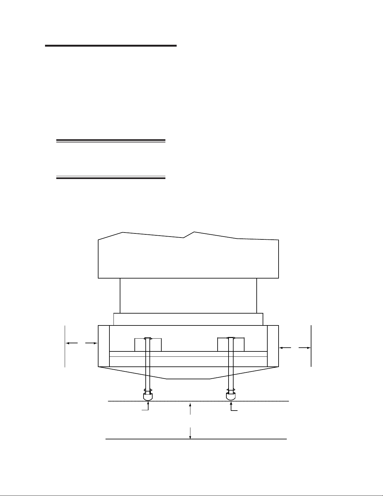
Figure 2-1 shows the clearances required for
the spreader/feeder. The dimensions noted are the
minimums recommended for efficient production
and service, as well as maintenance access. It is
strongly recommended that enough clear space
be provided around the spreader/feeder to allow
for efficient access.
NOTE: The correct location of
the spreader/feeder is of extreme
importance.
The site must have a level, sturdy floor capable
of supporting the spreader/feeder’s weight without
significant flexing. For weight specifications
and other technical information refer to the
APPENDIX, Technical Specifications.
No special foundation, floor grouting, or
installation of anchors is required. Generally, the
locking floor pads will hold the spreader/feeder
in position and still allow for repositioning when
necessary.
Floor grouting or installation of anchors
may be required to comply with local codes or
conditions, or aboard a ship.
Figure 2-1: Recommended clearances for installation of the Edge Maxx.
ironer
Chicago Edge Maxx
input input
915 mm
36”
915 mm
36”
72”
1830 mm
TOC
INDEX
Table of contents
Popular Spreader manuals by other brands

Agri-Fab
Agri-Fab 45-02153 owner's manual

SnowEx
SnowEx SP-1675 owner's manual

L.T. Rich Products
L.T. Rich Products 135LB owner's manual

Tatu Marchesan
Tatu Marchesan DCA2 MC 2500 Operator's manual

Amazone
Amazone ZG-B 5500 Special operating manual

LEHNER
LEHNER MiniVario E Operating instructions with parts list


Craftsman
Craftsman 486.1994 owner's manual

Buyers
Buyers SaltDogg SHPE2500 Series manual

SPYKER
SPYKER SPY50L-2S Operator's manual

Vogal
Vogal SPREADMAX EX750 Operation Maintenance & Parts Manual

Hilltip
Hilltip Ice STRIKER 600 TR owner's manual

Trynex International
Trynex International TurfEx RS7200E owner's manual