D-2 Incorporated JF-WA1 User manual

JF-WA1 HYDRO-LIGHT SENSOR
480-003
August 22
1
D-2 INCORPORATED
HYDRO-
LIGHT
WATER PAD READER
JF-WA1
OPERATION MANUAL
REVISION 8.0
P/N 480-003
Revision History:
Rev
Date
Description
1
28JAN08
Written
AJF
2
16JUN11
undefined
AJF
3
09SEP11
Revised for format and content
AJF
4
05APR12
Include USB Power Option
AJF
5
02MAY14
Fix Appendix B, change company address
SWS
6
11NOV19
Change of Address
DLF
7
08APR20
Emphasize the use of provided power supply
SWS
8
29MAR21
Alter Email Address, RMA Verbiage
DLF
9
29AUG22
Update due to new shuttle targets and Calibration routines
SWS

JF-WA1 HYDRO-LIGHT SENSOR
480-003
August 22
2
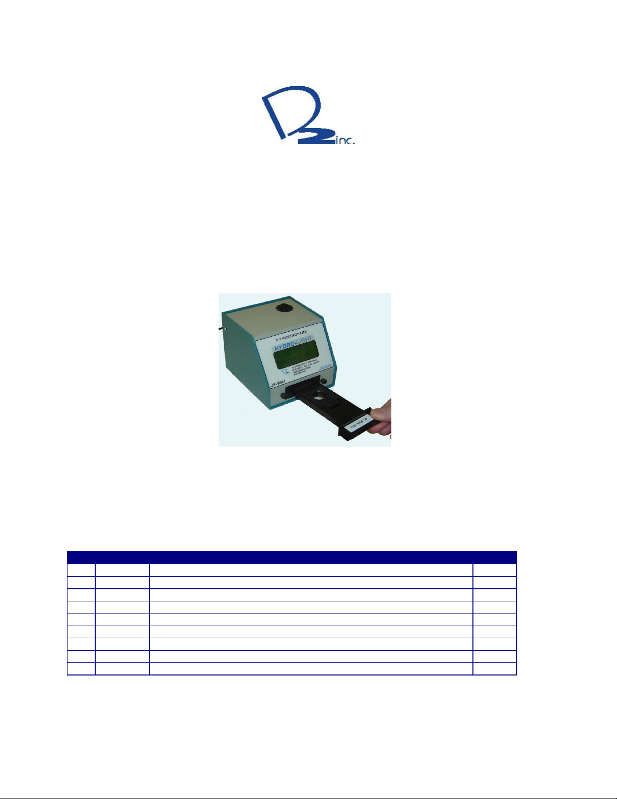
This manual covers the operational aspects of the D-2 JF-WA1 Hydro-
Light
Sensor. D-2
continuously strives to meet the full expectations of our customers and we welcome
comments on the structure, content and the ability of this manual to answer your
questions regarding our product. If you have any suggestions or comments, please
that future versions of this instrument may have additional commands, and the function
of the commands shown in this document may vary from the present operation.
TABLE OF CONTENTS
Notes for User:
.......................................................................................................................... 3
1.0 GENERAL DESCRIPTION.................................................................................................... 5
2.0 SPECIFICATIONS ................................................................................................................. 6
3.0 USAGE..................................................................................................................................... 6
4.0 THEORY OF OPERATION.................................................................................................... 7
Figure 1.....................................................................................................................................................8
5.0 OPERATION INSTRUCTIONS............................................................................................. 9
Figure 2...................................................................................................................................................10
Figure 3...................................................................................................................................................10
Figure 4...................................................................................................................................................10
6.0 FIELD VERIFICATION PROCEDURE............................................................................. 11
7.0 USB SERIAL DATA INTERFACE...................................................................................... 11
7.1 Port Settings.....................................................................................................................................12
7.2 Command Structure........................................................................................................................12
7.3 Continuous Data..............................................................................................................................13
7.4 Configuration/Calibration Constants............................................................................................13
7.5 Calibration Mode ............................................................................................................................13
8.0 CALIBRATION ..................................................................................................................... 13
8.1 Calibration Interval ........................................................................................................................13
8.2 Verification Tests.............................................................................................................................13
9.0 MAINTENANCE................................................................................................................... 14
APPENDIX A: LIMITED WARRANTY.................................................................................... 14
APPENDIX B: Serial Port Command List................................................................................. 16

JF-WA1 HYDRO-LIGHT SENSOR
480-003
August 22
3
Notes for User:
WARNING!
There
is
a
danger
to
life and
limb
or
a
risk
of
serious
injur
y
if
the notes on
safety
are
disregarded!
CAUTION!
There
is
a
risk
of
injur
y
and
damage
to
property
if
the notes on
safety
are
disregarded!
ATTENTION!
There
is
a
risk
of
damage
to
property
if
the notes on
safety
are
disr
egarded!
!
IMPOR
T
ANT
Notes on working procedures.

JF-WA1 HYDRO-LIGHT SENSOR
480-003
August 22
4
Read the instructions in this manual carefully before installing or starting the system.
Note throughout this manual the term JF-WA1 applies to all models of the instrument,
unless specific individual model numbers are detailed.
D-2 Incorporated will accept no liability for damages due to non-observance of this
manual.
ATTENTION!
If the instructions in the operating manual are not adhered to or are
inadequately adhered to, there shall be no entitlement to services
under the warranty.
Information in this manual is subject to change without notice and does not represent a
commitment on the part of D-2 Incorporated.
No part of this manual may be reproduced or transmitted in any form or by any means,
electronic or mechanical, without the prior written permission of D-2 Incorporated.
Where manuals are written in several languages, the text it was created in is considered
the original.
D-2 Incorporated
6 Otis Park Drive
Bourne, MA USA 02532
Phone: 01 508-329-2046
Telefax: 01 508-536-5206
E-Mail: [email protected]
Internet: http://www.D-2.com
© Copyright 2014, D-2 Incorporated, Bourne, MA, USA

JF-WA1 HYDRO-LIGHT SENSOR
480-003
August 22
5
1.0 GENERAL DESCRIPTION
The JF-WA1 Hydro-
Light
Sensor incorporates innovative optics and electronics
which use Digital Signal Processing (DSP) techniques to accurately determine the
fluorescence of water detector test pads in accordance with ASTM D3240. The
instrument will measure 1.0” test pads with free water in the range of 0 – 50 parts per
million (PPM), although it is optimized and normally used in the 0 to 35 PPM range.
The sensor displays the calculated value on the 2-line 2.25” x 0.90” Liquid Crystal
Display (LDC), and also offers a USB data output.
Although absolute calibration relies only on the sensor’s optical geometry, which
is very stable by design, the Hydro-
Light
Sensor continuously monitors internal
electronic circuits to guarantee calibration to be a maximum of a five year period.
Ambient Operating temperatures are compensated through the use of a built-in
temperature sensor and all calibration terms are stored in internal, non-volatile
memory. D-2 Inc. also provides reference pad shuttle to verify readings between
calibrations.
These attributes make the JF-WA1 very reliable and easy to use.

JF-WA1 HYDRO-LIGHT SENSOR
480-003
August 22
6
2.0 SPECIFICATIONS
Table 2
SENSOR SPECIFICATIONS
Parameter
Free Water
Range
0 –50 PPM
Accuracy
+/- 0.5 PPM (+/- 2%) of Reading
Resolution
0.1 PPM
Sensor Type
Optical LED Driven
Calibration
Internal Zero & Scale
Table 3
SYSTEM SPECIFICATIONS
ELEMENT
SPECIFICATION
Environmental
15 to 35 °C Operation
-10 to 60 °C Storage
Power
9.0 VDC ± 0.3 VDC,
Use Supplied Power Supply Only
USB Power*
Option via USB Cable
Certification ASTM
D3240
Certification Sensor
CE
* Consult Factory for USB Power Option Input
3.0 USAGE
The use of the Hydro-
Light
to determine the free water content of fuel products,
such as jet aviation and diesel fuels, should be conducted in accordance with ASTM’s
D3240 method.
A water detector test pad that has been properly prepared with a fuel sample
(method D3240) is placed into a JF-WA1 shuttle and then placed into the Hydro-
Light
.
The Hydro-
Light
calculates the free water content in parts per million (PPM), then
displays the digital value on the top line of the LCD readout.
The bottom line of the LCD is used for displaying pertinent information. It
toggles between the firmware revision, the last calibration (month/year) and the
measurement mode.

JF-WA1 HYDRO-LIGHT SENSOR
480-003
August 22
7
The measurement mode of the JF-WA1 can be set to either “Mode A” or “Mode
D”. The Hydro-Light can apply the ASTM D6708 Bias found between the existing
method sensor and the original Aqua-Glo®Instrument. The Bias was found to be
Hydro-Light Reading = Aqua-Glo®Reading * 1.22. This bias correction can be made by
the Hydro-Light. If the lower display indicates “Mode A” then the correction factor has
been applied internally in the Hydro-Light and the readings are equivalent to the
present ASTM D3240 method (in other words the unit reads the same as an Aqua-
Glo®). If the low information line indicates “Mode D” then the Hydro-Light reads in the
original D-2 Incorporated Calibration and values from the unit must be divided by 1.22
to equal the current ASTM D3240 Method. Units are shipped in “Mode A” for user
convenience.
4.0 THEORY OF OPERATION
The D-2 JF-WA1 Hydro-
Light
Sensor uses Light Emitting Diodes (LED’s) to
illuminate the water detector test pad, while it is inside the sensor chamber. The high-
performance detector receives the fluorescent light reflected back from the pad. The
instrument measures the amount of light received back to determine the concentration
of free water which came in contact with the pad as a result of its exposure to the fuel
sample. The display reads directly in PPM, and is scaled to the standard size 500 ml
fuel sample as outlined in ASTM D3240. If an alternate amount of fuel is sampled
through the pad the displayed number need only to be scaled by the ratio of the
amount of fuel sampled to the standard 500 ml sample size.

JF-WA1 HYDRO-LIGHT SENSOR
480-003
August 22
8
Figure 1
Major System Components
4.2"
AN ISO 9001:2000
CERTIFIED COMPANY
D-2 INCORPORATED
19 COMM ERCE PARK ROAD
1.2 PPM
POCASSET, MA U.S.A. 02559
WWW.D-2INC.COM
508-329-2046
4.2"
JF-WA1
HYDRO-LIGHT
4.4"
1. On-Off Switch
2. Wall Power Adaptor
3. USB Port
4. Display (LCD)
5. Pad Shuttle

JF-WA1 HYDRO-LIGHT SENSOR
480-003
August 22
9
5.0 OPERATION INSTRUCTIONS
Step-by-Step Operation Procedure
1. Connect Hydro-Light power supply to power input on the rear panel of the unit (Figure 1) and plug into 90
–340 VAC 50/60 Hertz outlet. (Or USB Cable with USB Power Option Consult Factory)
2. Turn the Hydro-Light unit on with switch at the top of the chassis (Figure 1). The display will illuminate.
After 5 seconds, the top line of the display will show the text “Hydro-Light”. Allow the instrument to
acquiesce to room temperature once power is supplied. We recommend a warmup period of at least 10
minutes. The Hydro-Light unit is now ready to use. The lower display will indicate the next factory
calibration date.
3. If there is no pad present, the display should read “0 PPM”.
4. Remove the shuttle from the front drawer of the unit (see Figure 2).
5. Press down on the tab to open the shuttle cover (see Figure 3).
6. Using tweezers, insert the pad into the shuttle (see Figure 4). Ensure that the pad is centered in the recess
of the shuttle.
7. Let the cover close to hold the pad in place.
8. Re-insert the shuttle into the Hydro-Light drawer.
9. Allow 5 seconds for the Hydro-Light unit to fully update the pad reading after insertion. The display
number will momentarily flash each time an update occurs and the lower line will change displayed
information.
10. Your Hydro-Light will now display the PPM free water content of your 500ml sample
1
.
11. The Hydro-Light reads directly if the sample volume is 500ml. Correct the reading for other sample sizes
by multiplying the displayed reading by (500/Sample size in milliliters).
12. Remove the shuttle, then remove the test pad from the shuttle and discard the test pad.
13. With the use of specially developed polymer Verification shuttle targets, factory recalibration can be as
large as a five-year period. To verify calibration in the field, use the verification shuttle to ensure the
readings are within the specified limits. If ever the Verification shuttle does not meet the printed
specifications, contact D-2 Inc.
1
Note: The Hydro-Light can apply the ASTM D6708 Bias found between the existing method sensor and the
original Aqua-Glo®Instrument. The Bias was found to be Hydro-Light Reading = Aqua-Glo®Reading * 1.22.
This bias correction can be made by the Hydro-Light. If the lower display indicates “Mode A” then the correction
factor has been applied internally in the Hydro-Light and the readings are equivalent to the present ASTM D3240
method (in other words the unit reads the same as an Aqua-Glo®). If the low information line indicates “Mode D”
then the Hydro-Light reads in the original D-2 Incorporated Calibration and values from the unit must be divided by
1.22 to equal the current ASTM D3240 Method. Units are shipped in “Mode A” for user convenience.

JF-WA1 HYDRO-LIGHT SENSOR
480-003
August 22
10
Figure 2
Figure 3
Figure 4

JF-WA1 HYDRO-LIGHT SENSOR
480-003
August 22
11
6.0 FIELD VERIFICATION PROCEDURE
Note: Verification is at the option of the user and will not change the calibration of the instrument. The
instrument will remain calibrated over the entire calibration interval if use as described within this
document is adhered to.
Step-by-Step Operation Procedure
JF-WA1 HYDRO-LIGHT VERIFICATION USING THE H&L-SHUTTLE
Technical Application Note 11-008
The JF-WA1 Hydro-Light H&L Shuttle Option allows immediate verification of the Hydro-
Light Calibration in the field. The H&L Shuttle has convenient low and high range color
standards mounted one on each side. With the test pads fixed in the shuttle the user has far
less handling of the verification pads keeping them cleaner and more protected. The H&L
Shuttle has the verification values marked in PPM Water content on each side.
Note: The H&L Shuttle should be protected from sun light at all times to prevent
bleaching of the color standards. The shuttle must not be left in the Hydro-Light
reader to prevent bleaching of the color standards by long term exposure to the
reader excitation LED light.
The Hydro-Light calibration is valid for a five-year period, if and only if the Verification
shuttle reads within its specified values. Hydro-Light verification can be performed on any
basis as needed by your facilities laboratory interval requirements. After a five-year period,
the color standards should be replaced and factory calibration should be performed. In the
event that the Hydro-Light fails to verify, a field calibration of the unit can be performed
using the H&L Shuttle, consult Application Note 11-009.
Procedure:
Remove the H&L Shuttle from its protective cover. Check the H&L Shuttle Calibration date
is valid (labeled on end of shuttle). Also, ensure the serial number of the verification shuttle
matches the serial number on the rear panel of the JF-WA1 being examined. Verification is
performed simply by insertion of the H&L Shuttle into the Hydro-Light on each side.
Confirm that the value displayed in PPM is within the range printed on the shuttle handle,
then remove, turn over, insert and verify the second side in the same manner. Return the
H&L Shuttle to its protective cover.
For More information please contact D-2 Incorporated.
Shuttle placed into JF-WA1
on Low Side
Shuttle placed into JF-WA1
on High Side
JF-WA1-H&L-SHUTTLE

JF-WA1 HYDRO-LIGHT SENSOR
480-003
August 22
12
7.0 USB SERIAL DATA INTERFACE
The JF-WA1 has an industry standard USB Interface. To properly connect to the
sensor certain USB drivers are needed. These drivers may or may not be already loaded
on your computer. These drivers can be found online from
http://www.ftdichip.com/Drivers/VCP.htm and looking for the FT232R product line. This
USB connection will have properties of a virtual serial port and the connection shall
automatically be given a comport number. This Comport number will be needed for
communications with the sensor through a Windows®terminal software program.
All instrument calibration constants and configurations are stored in internal non-
volatile memory. The unit also has programmable optics temperature compensation
constants.
7.1 Port Settings
When powered the unit commences operation to the USB Driver. The serial port
will not be recognized by the host computer unless the JF-WA1 is powered and turned
on.
The serial port should be configured for:
57600 Baud
8 Data Bits
No Parity
1 Stop Bit
No Handshaking
Consult your computer manual for USB port configuration and use.
7.2 Command Structure
(Note: Reponses from the JF-WA1 are represented by 10 pt ARIAL Black Font)
(Notes: commands sent to the JF-WA1 are represented by 12 pt Arial Bold Green
Font)
•All commands sent to the JF-WA1 are case insensitive.
•Each command must be followed with a carriage return <CR> (Enter key
of the computer’s keyboard).
•To read individual parameter the command name is entered followed by
the <CR>. For example, to read the offset value, the command would be
entered as N2<CR>.
•To set an individual parameter, you use the command name + the “=” +
parameter value. For example, N2=3.11<CR>

JF-WA1 HYDRO-LIGHT SENSOR
480-003
August 22
13
7.3 Continuous Data
The JF-WA1 has the ability to output continuous data to the serial port. To have
the unit send data continuously, send the SC<CR> command. The unit will commence
sending data at the data rate and current averaging rate. To stop continuous data,
resend the SC<CR> command.
7.4 Configuration/Calibration Constants
When not set in continues data mode, the unit awaits user instructions such as
calibration constants, or settings, etc. All instrument calibration constants and
configurations are stored in internal non-volatile memory. See Appendix B for command
definitions.
7.5 Calibration Mode
In CALIBRATION OPEN MODE the unit runs the same but adds an additional digit
to readings taken and outputs the internal temperature to the display. This mode is
entered by the command “TCAL<CR>”. The SET CONTINUOUS “SC” command also
operates in Calibration Mode. This mode is not stored in EEPROM as such power
cycling will revert the unit back to normal operation.
8.0 CALIBRATION
8.1 Calibration Interval
The D-2 JF-WA1 Hydro-
Light
sensor should be calibrated by the factory, only.
New target shuttles (polymer) have been incorporated to increase the calibration period
to maximum of five years, if and only if, the shuttles read within their published
specifications. Each shuttle has specifications printed on them. Each unit is “married” to
the shuttle it was calibrated to, so that no other shuttle should be used as a verification.
Each shuttle has the corresponding serial number to the married unit. The instrument
has no internal electrical adjustments that need to be maintained inside this period and
the housing should not be opened outside of the factory. Doing so voids the warranty.
8.2 Verification Tests
The best indicator of static operation of the sensor is the use of verification pads;
see “field verification section” for complete instructions.

JF-WA1 HYDRO-LIGHT SENSOR
480-003
August 22
14
9.0 MAINTENANCE
NOTE: There are no user-serviceable components inside the D-2 JF-WA1
Hydro
-Light Sensor. There are NO Electronic adjustments inside the sensor.
APPENDIX A: LIMITED WARRANTY
Subject to the limitations contained in “Limitation of Remedy & Liability” section, as shown
below, Seller warrants that products provided will perform to the ability of the published
specifications or Industry Method(s) claimed by the Seller. The Seller certifies that the goods
manufactured or services provided will be free from defects in materials or workmanship under
normal use and care until the expiration of the applicable warranty period.
Standard laboratory products, are warranted for twelve (12) months from the date of initial
calibration, which will be referenced by supplied documentation or electronically embedded into
the product’s memory or both.
Specialized equipment in the form of product line additive systems, also known as “Skids” are
warranted for twelve (12) months from the initial installation or eighteen (18) months from the
date of shipment by Seller, whichever period expires first.
Marine laboratory or deployment products, are warranted for twelve (12) months from the date
of initial calibration, which will be referenced by supplied documentation or electronically
embedded into the product’s memory or both.
If Buyer discovers any warranty defects and notifies Seller thereof in writing during the
applicable warranty period, Seller shall, at its option, correct any errors that are found by Seller
in the firmware or Services or repair or replace F.O.B. point of manufacture that portion of the
Goods or firmware found by Seller to be defective, or refund the purchase price of the defective
portion of the Goods/Services. All replacements or repairs necessitated by inadequate
maintenance, normal wear and usage, unsuitable power sources or environmental conditions,
accident, misuse, improper installation, modification, repair, storage or handling, or any other
cause not the fault of Seller are not covered by this limited warranty, and shall be at Buyer’s
expense. Seller shall not be obligated to pay any costs or charges incurred by Buyer or any
other party except as may be agreed upon in writing in advance by Seller. All costs of
dismantling, reinstallation and freight and the time and expenses of Seller’s personnel and
representatives for site travel and diagnosis under this warranty clause shall be borne by Buyer
unless accepted in writing by Seller. Goods repaired and parts replaced by Seller during the
warranty period shall be in warranty for the remainder of the original warranty period or ninety
(90) days, whichever is longer. This limited warranty is the only warranty made by Seller and
can be amended only in a writing signed by Seller. THE WARRANTIES AND REMEDIES SET
FORTH ABOVE ARE EXCLUSIVE. THERE ARE NO REPRESENTATIONS OR WARRANTIES OF
ANY KIND, EXPRESS OR IMPLIED, AS TO MERCHANTABILITY, FITNESS FOR PARTICULAR
PURPOSE OR ANY OTHER MATTER WITH RESPECT TO ANY OF THE GOODS OR SERVICES.

JF-WA1 HYDRO-LIGHT SENSOR
480-003
August 22
15
LIMITATION OF REMEDY AND LIABILITY: Seller shall not be liable for damages caused
by delay in performance. The remedies of buyer set forth in this agreement are exclusive. In
no event, regardless of the form of the claim or cause of action (whether based in contract,
infringement, negligence, strict liability, other tort or otherwise), shall seller’s liability to buyer
and/or its customers exceed the price to buyer of the specific goods manufactured or services
provided by seller giving rise to the claim or cause of action. Buyer agrees that in no event
shall seller’s liability to buyer and/or its customers extend to include incidental, consequential or
punitive damages. The term “consequential damages” shall include but not be limited to, loss
of anticipated profits, revenue or use and costs incurred including without limitation for capital,
fuel and power, and claims of buyer’s customers.
Equipment supplied by but not manufactured by D-2 Incorporated, is supported only to
the extent of the original manufacturer’s original warranties. All OEM sensors which
utilize electrodes (oxygen cartridges, pH, ORP, etc.) is warranted at the time of
shipment, and shall perform upon initial installation within stated specifications. If the
product proves to be defective within the OEM’s warranty, we will replace the product
or defective part with a similar model, product or part, but only to the extent that the
OEM will warrant.
All returned products must be accompanied by a Returned Material Authorization (RMA)
number issued by D-2 Incorporated. Shipments will not be accepted without the RMA
number. An RMA number can be obtained by calling Customer Service Department at
508-329-2046 or by emailing Sa[email protected]. D-2 can supply a customer return
Procedure and a D-2 Service Request form which can be filled out and returned with
the instrument to answer the following parameters…
Return Material Authorization Number
Model/Serial Number
Brief Description of the Problem
Customer Contact/Telephone Number
CALIBRATION SERVICE POLICY
A calibration only service is available for JF-WA1 Hydro-
Light
Sensors.
The service is limited to instruments requiring only calibration and minor adjustment.
Instruments that are not operating properly and require repair or replacement parts will
not be covered. If repair is necessary the customer will be contacted and apprised of
the additional cost. The customer will be charged the standard repair cost, which
includes repair and calibration. In the event that the customer does not approve repair,
the unit will be returned in "as received" condition and the teardown and inspection
charge will be invoked.

JF-WA1 HYDRO-LIGHT SENSOR
480-003
August 22
16
APPENDIX B: Serial Port Command List
Function Command
Save parameters ST
List all variables LI
Get sensor serial number SN
Get firmware version VR
Toggle the continuous data mode SC
Get list of help commands F1
Bias Mode* PR
0 = ASTM BIAS Mode Not Applied
1 = ASTM BIAS Mode Applied
Optic Compensation Temp Reference TR
Optic Slope Value (ppm/count) N1
Optic Offset Value (ppm) N2
Optic Temperature Coefficient (ppm/°C/ppm) N3
Temperature Channel Offset (°C) T1
BIAS Reading Value M1
*all commands listed after and including this one have the ability to read or set the
parameter.
Table of contents
Popular Test Equipment manuals by other brands

Hanna Instruments
Hanna Instruments HI 38035 instruction manual

Kaiweets
Kaiweets HT106B user manual

Agilent Technologies
Agilent Technologies E8285A manual

AquaLabo
AquaLabo ORCHIDIS FLOTTATEST user manual

Keysight Technologies
Keysight Technologies 85052B User's and service guide

REED
REED VC05 instruction manual