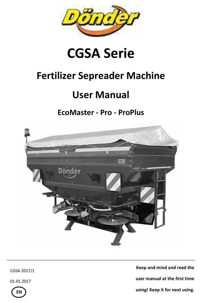
DÖNDER WAGON Series User manual

01.10.2013
- 1 -
CONTENTS PAGE NO
1. INTRODUCTION OF THE MACHINE AND THE AREAS OF USE…...........2
2. WARRANTEE.......……………………............................................................2
3. NONWARRANTABLE SITUATIONS...............................……………...........2
4. RULES GOVERNING SECURITY AND PREVENTION OF ACCIDENTS...2
5. SECURITY SIGNS.........................................................................................3
6. PORTAGE OF THE MACHINE.....................................................................4
7. CONTROLLING THE MACHINE……………………………………………....5
8. MAINTENANCE………………………………………………………….……...7
8.1. DAILY MAINTENANCE ……………………………………………...7
8.2. GENERAL MAINTENANCE............................................................8
9. TECHNICAL PROPERTIES..........................................................................10
10. READING FERTILIZER POURING TABLE......……………………………....11
11. ADJUSTING THE EXTENT OF THE WORK AND THE AMOUNT…….......12
12. BALANCED SPREADING FOR DIFFERENT FERTILIZERS......................12
13. FERTILIZERS POURED FROM 6 METERS HIGH......................................17
14. FERTILIZERS POURED FROM 16 METERS HIGH....................................19
15. FERTILIZERS POURED FROM 18 METERS HIGH...................................21
16. FERTILIZERS POURED FROM 24 METERS HIGH...................................23

01.10.2013
- 2 -
1 INTRODUCTION OF THE MACHINE AND THE AREAS OF USE
Wagon is manufactured by Dönder in compliance with European standards. Wagon’s most
appropriate areas of use are seed drilling and fertilizer spreading. Also it is also capable of
pouring mineral fertilizer in granule or powder form; as well as salt; sand and pallet poultry
manure.
2 WARRANTEE
Once you receive the delivery of the machine please check whether there is a
deficieny in the hardware or a damage caused by portage or not; and which you should have
confirmed by whoever consigned the machine to you. You may notify your complaints to our
company latest within seven days. Complaints shall be considered provided that the
customer has fully complied with rules of warrantee.
Machine is warranted against defects of manufacturing or of material for one year
starting from the delivery date. Warrantee is limited to the repair or replacement of defective
parts in compliance with the rules set by the manufacturer.
Distributors or users may not have any claims against manufacturer originating from
accidents they caused or caused by misuse. Warrantee shall be void if the machine has
been altered without authorisation by the manufacturer; or if different parts have been
mounted on it, and if the machine has been damaged by either of those situations.
Warrantee shall be expired, if the values specified in technical data have been
exceeded; if machine has been inappropriately used, or periodical maintenance has failed.
Our company conducts continuous works for improving the machines, so it reserves
the right for making updates on the machines. Thereof, our company is not obliged to apply
the modifications presented with the new model machines also to the machines sold
previously.
3 NONWARRANTABLE SITUATIONS:
Using specified power take off speed of the machine above (540 d/minutes).
Not mounting original shaft on the machine.
Damaging machine by sudden stops and moves while the machine is connected to
the tractor and operating.
Using machine beyond the specified technical values.
Using machine outside the intended use.
Not using original spare parts specified by the manufacturer.
Making modifications on the machine without the authorisation by the manufacturer.
4 RULES GOVERNING SECURITY AND PREVENTION OF ACCIDENTS
oFor secure use and traffic, check the machine and the tractor before operating.
oConnect the machine to the tractor by means of required devices and in compliance
with the rules.
oDuring operation and portage of the machine, no humans should be on the machine.
oParts, moving parts and functions of the machine should be mastered before
opearating.
oObey the traffic rules on the roads open to the traffic.

01.10.2013
- 3 -
oFamiliarize with the rules governing health, security and prevention of accidents apart
from the ones specified in this manual.
oWarning and information signs posted on the machine includes significant information
for secure use. Meanings of the those signs should be thorougly learned.
oCheck whether the lights and warning devices of your machine are intact and
properly operating or not.
oDo not violate the allowed limits of axle loads, weight, and portage.
oDo not leave the tractor while it is operating during portage.
oEnsure that there is no human on the operation site of the machine.
oNever touch the spreading disc part of the machine when it is operating.
5 SECURITY SIGNS
1 2 3 4
5 6 7
8 9 10
11 12 13

01.10.2013
- 4 -
14 15 16
17 18 19
20
1) Pay attention to shaft.
2) Power take-off speed is 540 rpm.
3) Warning! Do not enter between the machine and the tractor.
4) Check the manual.
5) Warning! Do not approach manually.
6) Machine loading/hanging point.
7) Grease lifting greasing point.
8) Do not connect trailer to the back of the machine.
9) Information about shaft.
10) Wash the machine with clean water upon completion of the work.
11)Danger of cutting and tearing on the hands and fingers due to the moving
elements.
12)Danger of crushing of the finger and hand due to accessible moving parts of the
machine.
13)Danger to be caused by materials or objects spread by the machine.
14)Danger of falling down or injury for climbing on to the top of moving machine.
15)Due to the operating and unprotected machine parts
16)Danger of arm’s or body’s drawing into the machine and injury due to the
operating and unprotected machine parts.
17)Danger of being crushed under the machine parts.
18)Touching of high pressured oil on the skin.
19)Danger of crashing or being crushed on the back of the machine during
connecting or disconnecting the machine.
20)Maximum allowed hydrolic pressure.
21)Indicates that machine is in compliance with the valid EU Directive.
6 PORTAGE OF THE MACHINE
During portage, lift the machine by the lifting points shown on the below picture.

01.10.2013
- 5 -
7 CONTROLLING THE MACHINE
Machine has four parts which need to be checked before operation.
Figure-1

01.10.2013
- 6 -
A. Hydraulic array connected to the tractor; enables starting and stopping the flow of
the material out of the vessel.
B. Array controlling band speed; the part on the left back side when looked at from the
back.
C. Cover level; sets the amount of the material flowing out of the vessel. By loosing the lever
handle, you can shift the indicator up down on the table. It is situated on the back of the
machine.
D. Spread extent setting; sets how many meters high fertilizer will be spreaded by the
machine. It has two parts.
First Part:
It is the part first spreading the fertilizer through the band. When you turn the handle in the
middle, angle of the tray changes. On the right side, there are angle levels indicated by
letters such as D,E,F.
When you shift the array N, spreaded material is consantrated in the center of the work
extent.
When you lower the array, and shifted in A direction, spreaded material is disposed in bulks
outside the work extent.
There are small handles on both sides of the handle in the middle. These handles fixe the
wings marked 4-6t. By moving the wings, it is possible to spread the fertilizer close to the
center or the edges of the disc; which affects the width of spreading.
When the wings are moved towards the level 9 ( fertilizer poured to the point close to the
center of disc), then spreading increases the extent of work.
When the wings are moved towards the level 1 (fertilizer poured to the point away from the
center of disc) decreases the width of spreading.

01.10.2013
- 7 -
Second Part;
Changing the positions of wings on the disc affects the width of spreading. As the position of
the wing gets close to the position 1 on the disc, width of spread increases. Turning direction
of the discs, and the connection of the wings are as shown on the below pictures.
Short wings on the disc, much more influence the center of extent of the spreading task.
As for the longer wings, they carry material to the edges of the width of spreading task.
Also there is a small cover on the short wing. As the cover is opened, fertilizer is more
spreaded on the center; as the cover is closed spreaded amount of the fertilizer is more
decentered. Driving Direction
Rotation Direction of Discs
8 MAINTENANCE
When the machine is connected to the tractor, please avoid maintenance and cleaning.
Perform maintenance in the specified intervals of regular operation. When the machine is
exposed to heavy and long term operation, increase the frequency of maintenance.
Maintenance guidance is intended to reduce the wearing out, and prolong the life of the
machine,so as to ensure good and efficient operation.
8.1 DAILY MAINTENANCE
At the end of each day of operation, machine should be completely cleaned; any kind of
waste, humid materials should be removed and cleaned.

01.10.2013
- 8 -
8.2 GENERAL MAINTENANCE
1. Nuts and bolts should be checked each 50 hours.
2. Pto shaft should be greased every 10 hours.
3. By detaching their covers, every 10 hours check the tightness of the straps which
rotate the discs. See picture 2.
4. Every 5 hours, grease the array controlling band speed shown with code B at Picture
1. Grease the gears every 10 hours by removing the cover.
5. Every 50 hours, grease the parts indicated on pictures No 4,5,8,9 on greasing schema by
grease gun.
6. Every 50 hours, grease the shaft parts indicated on pictures No 3,8,10 on greasing
schema by grease gun.
7. Every 100 hours, grease the parts indicated on pictures No 1,2,10 on greasing
schema by grease gun
8. Check the tightness of wheels’ screws after first 50 km.
Picture 2

01.10.2013
- 9 -

01.10.2013
- 10 -
9TECHNICAL PROPERTIES
MODEL
W4000
W 6000
CAPACITY (liter)
4000
6000
WORK EXTENT (m)
6-24
6-24
MAX. LOADING (kg)
4000
6000
WEIGHT (kg)
1540
1700
QUANTITY OF WHEELS
4
4
MAX. P.T.O. SPEED
540
540
REQUIRED TRACTOR POWER
110
110
RUBBERS
10,0 / 75 - 15,3
10,0 / 75 - 15,3
A. LENGTH
4720
4720
B. WIDTH
2020
2020
C. HEIGHT(mm)
TILT
2470
2820
D. HEIGHT (mm)
WITHOUT TILT
2060
2410

01.10.2013
- 11 -
10 READING FERTILIZER SPEADING TABLE
Amount of fertilizer to be spreaded per hectare can be detected on the
SPRADING TABLE on the back of the table.
On the table, there are columns
indicating work extent. Those columns
indicate the amount of the fertilizer per
liter to be spreaded according to the
work extent.
Work extent column is divided into
two parts:
Z:12-60 column ; in this column
amount of the fertilizer to be poured per
hectare is less.
Z:22-54 column ; in this column,
amount of the fertilizer to be spreaded
per hectare is more compared to other
column.
Preferably, generally Z:22-54
column is used.

01.10.2013
- 12 -
Machine is mounted according to Z:22-54 jags. Explanations and examples shall be
made with reference to column Z:22-54.
If you like to use columns 12-60, stand on the left back side of the machine; and remove
the moving wheels and gear box cover. Loosen the tension gear, attach the chain on gears
22-54 to 12-60 gears and tighten the tension gear. In this case, you can use the values on
12-60 columns.
Values indicated on SPRADING TABLE, indicates the amount to be spreaded on the
hectare in liters. In order to use the table, you need the converse the amount to be spreaded
from kg into liters. When you divide the amount (kilogram) by the specific weight, of the
fertilizer to be spreaded per hectare, you will find the amount of the fertilizer to be spreaded
per hectare in liters.
By adjusting the adjusting lever according to the value on the table, you will find liter-
kilogram to be spreaded per hectare.
Specific weight of the urea :0,74 kg/lt
Weight of DAP: 1,152 kg/lt
Specific weight of super phosphate: 1,085 kg/lt
Specific weight of TSP:0,989 kg/lt
11 ADJUSTING THE EXTENT OF THE WORK AND THE AMOUNT
30 kg urea fertilizer is intented to be spreaded on decare of 12 meters wide.
If 30 kg for 1 decare (1000 m2) then 300 kg urea fertilizer is spreaded per one hectare.
Open the page about fertilizers spreaded 12 meters wide (page 19)
Find the table titled urea and choose the table used for urea.
(if the urea to be spreaded can not be found on the page of fertilizers spreaded in 12 meters,
choose any fertilizer according to the grain size, choose any fertilizer according to the
similarity with grain size.)

01.10.2013
- 13 -
We shall use the line where number 317 which is closest to 300 kg and situated on the kg/ha
column. By applying these values, our machine can be adjusted to spread 317 kg urea
fertilizer over a hectar of 12 meters wide. To achive that, follow the below steps.
1. Discharge cover level column shall be shifted to the position 3. ( See the discharge
cover level picture)
2. Bracket scale 2 shall be shifted to the position (E) (See the picture bracket scale 1)
3. Bracket scale 2 shall be shifted to the position (9) ( See the picture bracket scale 2)
4. Wing positions shall be shifted to the positions A (1), B (3), W (6) ( See the wing
positions picture)
5. It should be P.T.O 540 (Tale axle of the tractor).
l/ha is 428 indicates that 428 liters urea fertilizer shall be spreaded over the hectare.
Now our machine is in the position to spread 300 kg urea fertilizer over a hectar (10 decare)
of 12 work extent wide.
12 BALANCED SPREADING FOR DIFFERENT FERTILIZERS
For the fertilizers to be spreaded, spreading tables have been formed. If the fertilizer to
spread is not found on spreading table, you can yourself adjust the spreading extent.
Example:
1. First determine the volume and grain size of the fertilizer to be spreaded. In order to
detect the volume, you will need a container of 1 liter capacity and a precision
balance. Pour the fertilizer into the container; shake the container until no space left
inside. Also note down the kilogram of the fertilizer in the container of 1 liter. This
value is the volume of the fertilizer to be spreaded, in other words, the specific weight.
2. Lets suppose that we find the density as 1 kg/l.
3. Fertilizer closest to the detected volume is selected on the table of fertilizers spreaded
according to their meters.
4. Fertilizer closest to the detected volume is selected from the table of fertilizers
spreaded according to their meters. Volume of Superphosphate is 1,085. It is closest
to the volume of fertilizer to be used. We will use the value of Superphosphate in the
table. Flow wing adjustments are made according to the amount of the fertilizer to be
spreaded on the hectare.
5. Supply 5 pieces of catch pits in the measure specified on the picture.

01.10.2013
- 14 -
6. Put the 5 catch pits in order in regular intervals in work extent. Spread fertilizer the
way shown on the picture, and follow the direction shown by arrow.
7. Separately weigh and note down the fertilizers poured into the catch pits in an order
according to their position. If you want this measure to be more accurate, you can
work with more catch pits in frequent and regular intervals.
8. Average value is estimated based on the below given formula.
Average value= Amount in the first pit + Amount in the second pit + ………. + 5.
Amount in the pit/5

01.10.2013
- 15 -
9. Percentage collected by each pit is estimated. Five values of percentage are found.
Percentage of the first pit = amount of fertilizer (gr) collected by the first pit/average
value x 100.
10. On the below schema, estimated percentage value of the pits according to meters is
drawn.
11. If a schema such as the one above is found which tells us that the machine spreads
less fertilizer on the center and more fertilizer on the sides of the work extent. In the
most ideal fertilizer schema, content percentage in each pit is equal.
12. First shift the long wings up to a higher position of disc. If the wing is in number 2
position, attach it to 3,4,5. If the fertilizer is still not sufficient on the center, shift the
short wing to a higher position.
13. In the case of a schema such as the one below, shift the long wings on the disc down
to a lower position. If there is not much change happened in the schema, also shift
the short wings to a lower position.
14. In the ideal adjustment, a schema similar to the one below is found.

01.10.2013
- 16 -
15. In cases of concentration or spreading of less fertilizer in the very center of the work
extent, adjustment can be managed by opening/ closing the cover on the short wing.
Adjustments made here will only influence the center of work extent in minimum level.
If the cover is opened, more fertilizer will be spreaded on the center of the work extent.
If the cover is closed, less fertilizer will be spreaded on the center of work extent.
This manual suits for next models
2
Table of contents
Other DÖNDER Spreader manuals