Meyer's 3465 User manual

Manufactured in DORCHESTER, WISCONSIN by
MEYER’S EQUIPMENT
Mfg. Corp.
INSTRUCTION AND PARTS BOOK –Rev. U
HEAVY DUTY MANURE SPREADERS
MODELS: 3465
DO NOT –Operate This Spreader Until You Have
Completely Read This Book!
NEVER –Repair or Clean This Spreader While PTO
is Engaged!

2 | P a g e M o d e l 3 4 6 5
MODEL SPECIFICATIONS
Loading Height
60”
Width of Box Inside
61-1/4”
Overall Width
106-1/2”
Length of Box Inside
213”
Depth
37”
Overall Length
27’ 5”
Height to Top of Upper Beater
73”
App. Capacity –Struck Cu. Ft.
308
App. Weight –Empty
7000 lbs.
Apron Chain (Standard)
Twin #67P11
Apron Chain (Optional)
Twin #667XH Pintle
Top Beater
Standard
Spindle Diameter
3”
Spindle Load Rating –Each
8,000 lbs.
Tire Size (Standard)
425-65R x 22.5
Tire Size (Optional)
--
PTO Speed
1,000 RPM
Min. Tractor Horsepower
120 HP
Min. Hydraulic Flow
14 GPM

M o d e l 3 4 6 5 3 | P a g e
INTRODUCTION
Congratulations on the purchase of your new
Meyer’s Manure Spreader. With its optional
equipment, this is the simplest, most flexible
system on the market today. With proper operation
and preventative maintenance, it will last for many
years.
This SAFETY ALERT SYMBOL means
ATTENTION! BE CAREFUL! YOUR SAFETY
IS INVOLVED! It stresses an attitude of HEADS
UP FOR
SAFETY. When you see this symbol, be
alert to the
possibility of PERSONAL INJURY and
carefully read
the message that follows.
WARNING:
NEVER OPERATE WITHOUT ALL COVERS,
SHIELDS AND GUARDS IN PLACE. KEEP
HANDS,
FEET AND CLOTHING AWAY FROM
MOVING
PARTS. SOME COVERS AND
GUARDS HAVE
BEEN REMOVED FOR
ILLUSTRATIVE PURPOSES
ONLY IN THIS
MANUAL. FAILURE TO HEED MAY
RESULT
IN SERIOUS PERSONAL INJURY OR
DEATH.
At the front of this manual is a Product Registration
and Inspection Certificate. Be sure your dealer has
completed this certificate and forwarded a copy to the
manufacturer to validate the manufacturer’s warranty.
The product model and serial number are recorded
on
this certificate for your convenience and for proper
identification of your spreader by your dealer and the
manufacturer when ordering repair parts.
The serial number plate is found on the upper left
front corner of the spreader box or stamped in the left
channel at the front. For information on ordering repair
parts, refer to the repair parts section of this manual.
Orders must list the complete description, correct part
number, and total amount required.
All references to right hand and left hand apply to the
product as viewed from the rear of the machine and
facing the direction of forward travel.
You are urged to study this manual and follow the
instructions carefully. Your efforts will be repaid in better
operation and service as well as a savings in time and
repair expense. Failure to read this manual and
understand the machine could lead to serious injury. If
you do not understand instructions in this manual,
contact either your dealer or Meyer’s Equipment
Manufacturing Corp.
This supersedes all previous published instructions.
Contact Information
Meyer’s Equipment Mfg. Corp.
601 W Center Ave.
P.O. Box 406
Dorchester, WI 54425
Phone: (715)-654-5200
Fax: (715)-654-5558
Email: emcdorchester@tds.net

4 | P a g e M o d e l 3 4 6 5
TABLE OF CONTENTS
INTRODUCTION ..................................................................................................................................................... 3
TABLE OF CONTENTS.............................................................................................................................................. 4
SAFETY........................................................................................................................................................... 6
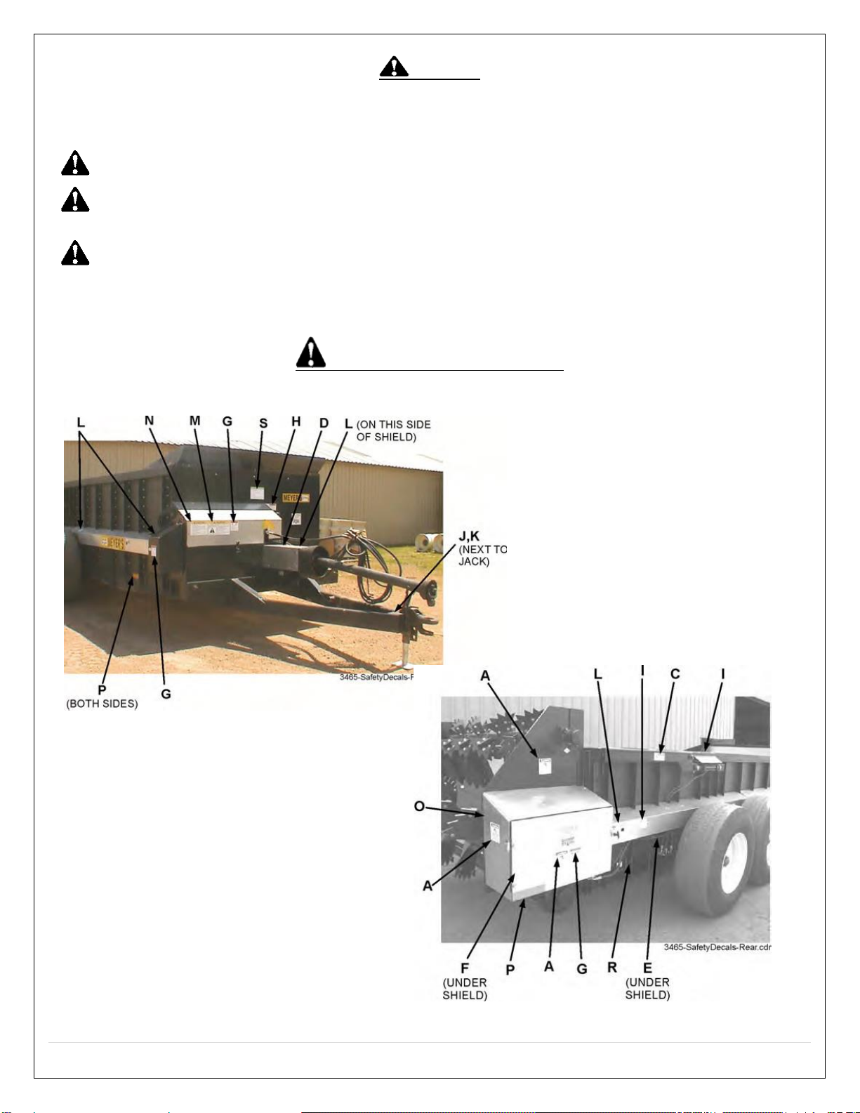
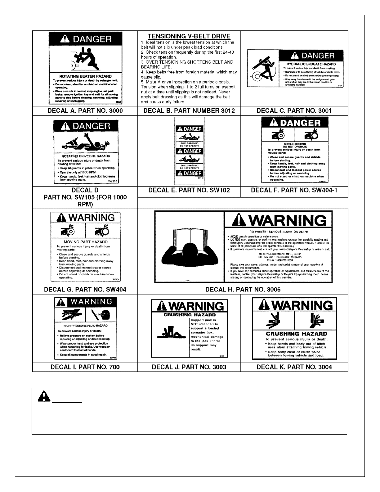
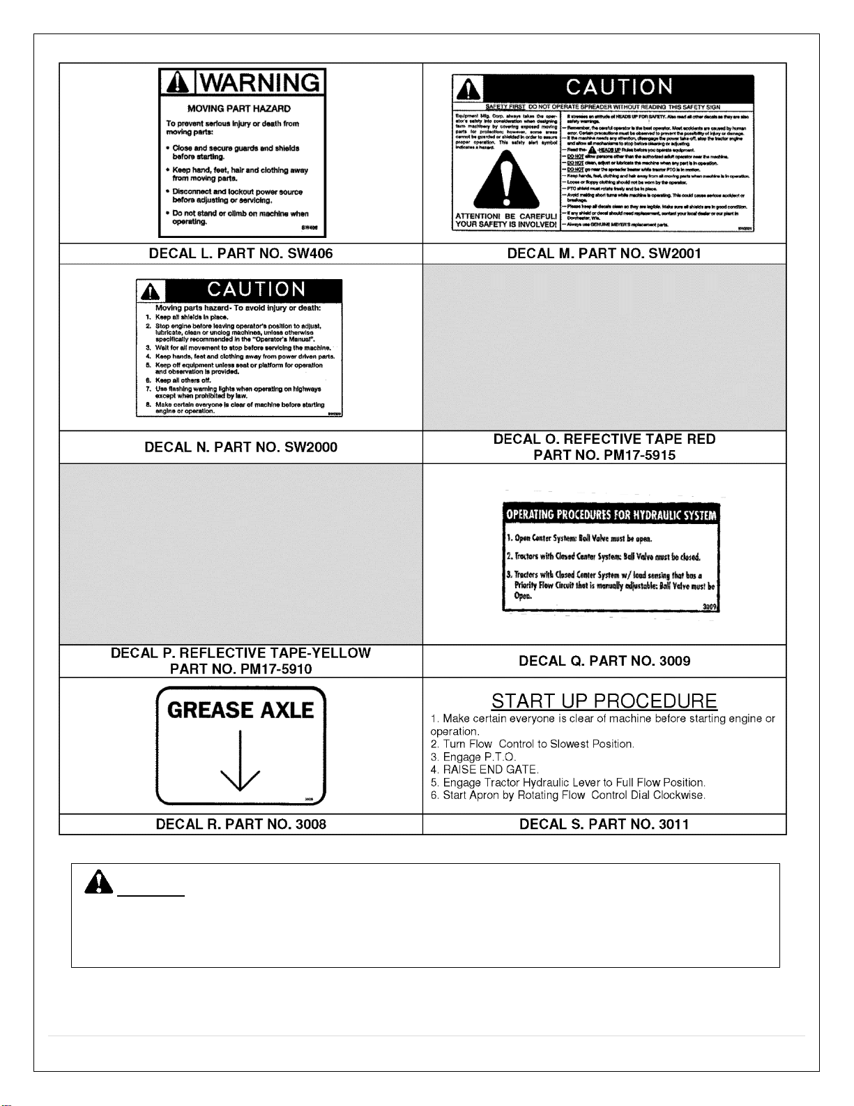
SAFETY SIGNS & DECALS ............................................................................................................................... 6
MANURE SPREADER SAFETY ....................................................................................................................... 10
MANDATORY SAFETY SHUTDOWN PROCEDURE ......................................................................................... 11
PRE-OPERATION .................................................................................................................................................. 12
GENERAL......................................................................................................................................................................12
TRACTOR HITCH &PTO REQUIREMENTS .....................................................................................................................12
TRACTOR SIZE REQUIREMENTS....................................................................................................................................13
Tractor Towing Size Requirements ..............................................................................................................................13
Material - Estimated Weights Per Cubic Foot..............................................................................................................13
HYDRAULIC SYSTEM.....................................................................................................................................................13
General ........................................................................................................................................................................13
Setup for Open or Closed Center Systems....................................................................................................................14
Electric Flow Control Installation .................................................................................................................................14
TRANSPORTING ...........................................................................................................................................................15
General ........................................................................................................................................................................15
Safety Chain Use ..........................................................................................................................................................15
Highway Lighting .........................................................................................................................................................15
OPERATION ......................................................................................................................................................... 16
TRACTOR HOOKUP.......................................................................................................................................................16
LOADING......................................................................................................................................................................16
UNLOADING.................................................................................................................................................................17
MAINTENANCE, ADJUSTMENTS, & LUBRICATION ................................................................................................ 18
WHEELS &TIRES...........................................................................................................................................................18
AUTOMATIC OVER RUNNING CLUTCH .........................................................................................................................18
ADJUSTMENTS .............................................................................................................................................................18
Apron Chain .................................................................................................................................................................18
Roller Chain Adjustment ..............................................................................................................................................18
Tensioning V-Belt Drive................................................................................................................................................18
LUBRICATION ...............................................................................................................................................................19
CLEANING &STORAGE.................................................................................................................................................21

M o d e l 3 4 6 5 5 | P a g e
REPAIR PARTS ...................................................................................................................................................... 22
MAIN FRAME &BOX PARTS .........................................................................................................................................22
HYDRAULIC END GATE &RELATED PARTS....................................................................................................................24
JACK ASSEMBLY ...........................................................................................................................................................25
AXLES, WHEELS, SPINDLES &RELATED PARTS..............................................................................................................26
SIDE DRIVE TRAIN.........................................................................................................................................................28
LUBE BANK, APRON SHAFT ..........................................................................................................................................29
APRON &RELATED PARTS, STANDARD 67P11 .............................................................................................................30
APRON &RELATED PARTS, OPTIONAL 667XH PINTLE ..................................................................................................32
BEATERS &RELATED PARTS .........................................................................................................................................34
FRONT DRIVE TRAIN.....................................................................................................................................................36
BEATER DRIVE TRAIN ...................................................................................................................................................38
UPPER BEATER DRIVE &RELATED PARTS .....................................................................................................................40
BEATER DRIVE GEAR BOX.............................................................................................................................................42
APRON DRIVE GEAR BOX..............................................................................................................................................44
PTO DRIVE SHAFT ASSEMBLY W/OVER-RUNNING CLUTCH AND GUARD, TRAILER TO TRACTOR.................................46
OVER-RUNNING CLUTCH ASSEMBLY............................................................................................................................47
HIGHWAY LIGHTING, STANDARD.................................................................................................................................48
HYDRAULIC ASSEMBLY, END GATE...............................................................................................................................49
HYDRAULIC ASSEMBLY, APRON, STANDARD ...............................................................................................................50
HYDRAULIC ASSEMBLY, APRON, ELECTRIC FLOW CONTROL........................................................................................52
HYDRAULIC ASSEMBLY, APRON, MANUAL FLOW CONTROL ........................................................................................54
OPTIONAL CHAIN OILING KIT .......................................................................................................................................56
LIMITED WARRANTY STATEMENT........................................................................................................................ 57

6 | P a g e M o d e l 3 4 6 5
SAFETY
A brief definition of signal words that may be used in
this manual:
DANGER: Indicates an imminentlyhazardous
situation that, if not avoided, will result in serious injuryor death.
WARNING: Indicates a potentiallyhazardous
situation that, if not avoided, could result in death or
serious injury,
and includes hazards that are exposed
when guards are removed.
CAUTION: Indicates a potentially hazardous
situation that, if not avoided, may result in minor or
moderateinjury.
SAFETY SIGNS & DECALS

M o d e l 3 4 6 5 7 | P a g e
CAUTION: IF ANY SAFETY SIGN BECOMES UNREADABLE FOR ANY REASON, THE SIGN
MUST BE
REPLACED WITH A NEW SIGN. IF THE SPREADER IS REPAINTED, ALL SAFETY SIGNS
MUST BE
REPLACED. CONTACT YOUR DEALER OR MEYER’S EQUIPMENT MANUFACTURING
CORP. IF YOU
REQUIRE ANY SHIELD OR SIGNS FOR REPLACEMENT.

8 | P a g e M o d e l 3 4 6 5
CAUTION: IF ANY SAFETY SIGN BECOMES UNREADABLE FOR ANY REASON, THE SIGN
MUST BE
REPLACED WITH A NEW SIGN. IF THE SPREADER IS REPAINTED, ALL SAFETY SIGNS
MUST BE
REPLACED. CONTACT YOUR DEALER OR MEYER’S EQUIPMENT MANUFACTURING
CORP. IF YOU
REQUIRE ANY SHIELD OR SIGNS FOR REPLACEMENT.

M o d e l 3 4 6 5 9 | P a g e
CAUTION: IF ANY SAFETY SIGN BECOMES UNREADABLE FOR ANY REASON, THE SIGN
MUST BE
REPLACED WITH A NEW SIGN. IF THE SPREADER IS REPAINTED, ALL SAFETY SIGNS
MUST BE
REPLACED. CONTACT YOUR DEALER OR MEYER’S EQUIPMENT MANUFACTURING
CORP. IF YOU
REQUIRE ANY SHIELD OR SIGNS FOR REPLACEMENT.

10 | P a g e M o d e l 3 4 6 5
MANURE SPREADER SAFETY
CAUTION
THERE ARE INHERENT HAZARDS ASSOCIATED WITH THE OPERATION OF A MANURE SPREADER.
FOR YOUR SAFETY:
Never Enter Spreader Box While In Operation For Any Reason.
Only Properly Instructed People Should Operate The Spreader. Do Not Allow Children Or Inexperienced Persons To
Operate Spreader.
Keep All Guards and Shields In Place. Moving Parts Can Crush And Dismember.
Clear The Area Before Equipment Start Up.
Keep Hands, Feet, and Loose Clothing Away From Moving Parts.
Do Not Go Near The Spreader Beaters While Machine Is Operating.
Make Sure The PTO Is Securely Locked To Both The Tractor And Spreader Before Operating The Unit.
Do Not Operate The PTO At Speeds Higher Than The Manufacturers Recommendations.
Highway Traffic Is Not To Exceed 20 Mph. The Tires Supplied Are For Farm Use Only And Are Not Designed For
Use Above This Speed Unless Equipped With High Speed Highway/Off-Road Farm Tires.
Use Adequate Safety Chains When Towing The Spreader.
The Use of a Slow moving Vehicle Sign Is Required on All Public Roads Unless Equipped with Flashing Hazard
Lights. Obey All Applicable Highway Safety Laws And Rules.
Always Use A Tractor Large Enough To Provide Sufficient Braking Assistance When Towing A Loaded Spreader.
Use Caution When Traveling Over Uneven Terrain And When Approaching Stops.
Do Not Load The Spreader Unless It Is Hitched To The Tractor.
Do Not Unhitch A Loaded Spreader From The Tractor, Leaving It Supported By Only The Jack.
Park Your Spreader on Level Ground and Place Blocks Ahead Of and Behind The Wheels Before Unhooking From
Tractor To Avoid Unexpected Rolling When Separated From The Tractor.
Do Not Allow Riders on Spreader.
FAILURE TO HEED MAY RESULT IN SERIOUS PERSONAL INJURY OR DEATH
CAUTION
THERE ARE ADDITIONAL HAZARDS ASSOCIATED WITHTHE SERVICE AND MAINTENANCE OF YOUR
SPREADER.
FOR YOUR SAFETY:
Inspect When First Delivered And Regularly Thereafter; That All Connections And Bolts Are Tight And Secure
Before Operating.
Retighten All Wheel Bolts After The First Hour Of Towing. Check Periodically Thereafter. See Maintenance, Wheels.
Maintain Proper Tire Air Pressure At All Times. See Maintenance, Tires.
Always Wear Eye Protection When Operating Or Servicing Spreader.
Be Sure All Movement Has Stopped, The PTO Is Disconnected, The Tractor Is Shut Off And The Ignition Key Is
Removed Before Servicing The Spreader Or Components.
Escaping Hydraulic Fluid Under Pressure Can Penetrate The Skin And Cause Serious Injury. Relieve All Pressure
From The Hydraulic System Before Connecting Or Disconnecting The Lines Or Making Repairs. Check All Hoses
and Fittings Before Start-up and Periodically During Operation.
Never Make Any Alterations Or Modifications To This Equipment.
FAILURE TO HEED MAY RESULT IN SERIOUS PERSONAL INJURY OR DEATH

M o d e l 3 4 6 5 11 | P a g e
MANDATORY SAFETY SHUTDOWN PROCEDURE
BEFORE unclogging, cleaning, adjusting, lubricating or servicing the unit:
1.
Disengage the tractor PTO.
2.
Shut off the tractor engine, remove the ignition key and take it with you.
3.
Wait for all movement to stop.
4.
Remove the Telescoping PTO Drive and ALL power connections from the tractor.
ONLY when you have taken these precautions can you be sure it is safe to proceed.
Failure to follow the above
procedure could lead to death or serious bodily injury.
Most farm accidents, like industrial, home, and highway accidents, are caused by the failure of some individuals to
observe simple and fundamental safety rules or precautions. For this reason, farm accidents, just as other types of
accidents, can be prevented by recognizing the causes of accidents and doing something about them before an
accident occurs.
Regardless of the care used in the design and construction of farm equipment, there are many points that cannot
be completely safe-guarded without interfering with accessibility and efficient operation.
A careful operator is the best insurance against an accident.
The complete observance of one simple rule would prevent many thousand serious injuries each year. That
rule is:
“NEVER ATTEMPT TO CLEAN, OIL, OR ADJUST A MACHINE WHILE IN MOTION”.
-NATIONAL SAFETY COUNCIL
NATIONAL SAFETYCOUNCIL
BEFORE ATTEMPTING TO OPERATE YOUR NEW SPREADER, BE SURE TO READ THIS OWNERS
MANUAL
AND FAMILIARIZE YOURSELFWITH THE MACHINE!
OBSERVE THE PRECAUTIONS IN THIS MANUAL FOR
SAFEOPERATION!

12 | P a g e M o d e l 3 4 6 5
PRE-OPERATION
GENERAL
Read the entire Owner's Manual before attempting to
operate this manure spreader. Before attempting any
maintenance or repairs; always be sure all rotating
parts
have stopped and that the tractor is shut off,
disconnect the
PTO, relieve all hydraulic pressure
and disconnect
hydraulic hoses.
WARNING
NEVER OPERATE SPREADERWITH ANY
GUARDS OR
SHIELDS REMOVED. FAILURE TO
HEED MAY RESULT
IN SERIOUS PERSONAL INJURYOR DEATH.
1.
Completely lubricate the unit as described in the
LUBRICATIONSection.
2.
Check and tighten the wheel lug nuts if required.
3.
Check and maintain the tire pressure according
to the
manufacturer’s recommendation.
4.
Check the entire unit for loose bolts, damaged or
loose
hydraulic fittings and hoses or other damaged parts.
5.
The tractor half of the PTO drive shaft assembly
must
be locked securely to the tractor output
shaft.
TRACTOR HITCH & PTO REQUIREMENTS
This spreader is designed to be operated by a 1000
RPM PTO Tractor output.
The PTO drive shaft assembly is designed to operate
with tractors conforming to the industry standard
shown
on Figure 1 for 1000 RPM PTO output.
A.D.M.A. Recommendations:
A tractor drawbar equipped with a clevis hitch (hammer-
strap) can cause interference with the PTO driveline IID
(implement input driveline). This
interference can cause
serious damage to the IID or
the IID telescoping
members. The clevis hitch on the
tractor must be
removed.
If the implement (fig 2, top view) is attached to a tractor
with a clevis hitch (hammer-strap) style drawbar,
the
hammer-strap must be removed to prevent damage to
the IID guarding or the IID telescoping members.
If the implement (fig 2, lower view) is attached to a
tractor with an offset in the drawbar, be certain it is in
the
down position to prevent damage to the IID
guarding or
the IID telescoping members.
Figure 1. Tractor Drawbar & PTO Dimensions
Figure 2. Clevis Hitch & Offset Drawbar

M o d e l 3 4 6 5 13 | P a g e
TRACTOR SIZE REQUIREMENTS
The spreader does not have brakes. Towing the
spreader
must be done safely. The ASAE (American
Society of
Agricultural Engineers) specifies that the
towing vehicle
should weigh at least 2/3 as much as
the loaded
implement to be reasonably safe towing at
speeds up to
20 mph. This (20 mph) is also the maximum recommended
towing speed for the spreader.
The loaded weight of your spreader will naturally vary
with
the moisture of the manure and you must consider that for
your conditions. The loaded weight capacities as specified
bythe spreader manufacturer
are as follows:
Tractor Towing Size Requirements
Use the following chart for calculating the minimum
tractor
weight.
MODEL
(Struck
Level)
Spreader Empty
Weight + Load = GW
Min. Tractor
Weight Up To
20 MPH
3465
(308 ft3)
7000 + _____ = _____
2/3 of Spreader
Gross Weight
Material - Estimated Weights Per Cubic Foot
Material
Lbs. / Cu. Ft.
Lime Sludge
110-115 LBS.
DryFeedlot Manure
63-65 LBS.
Chicken Litter
63-65 LBS.
Cake Sludge
62-65 LBS.
Semi-Solid Manure
58-60 LBS.
Pen Packed Manure
30-35 LBS.
Liquid Manure
63-65 LBS.
SOURCE: ASAE
NOTE: HEAPED LOADS HAVE SIGNIFICANTLY
HIGHER CAPACITIES RESULTING IN INCREASED
WEIGHT AND HIGHER CENTER OF GRAVITY,
REQUIRING EXTRA PRECAUTION DURING
OPERATION.
HYDRAULIC SYSTEM
General
There are two hydraulic circuits on the spreader:
One circuit powers the hydraulic end gate.
The second circuit powers the hydraulic apron
drive. A
check valve is installed in this circuit to
prevent
operating the apron in reverse.
Therefore, the tractor requires two sets of remote
ports,
one set for the hydraulic apron drive and one
set for the
hydraulic end gate.
Three types of hydraulic operating systems are available
for the apron drive on the spreader:
1. The Manual Flow Control system has an adjustable
flow control valve on the spreader which is manually
controlled bytwisting a “control hose” which
is
connected to the flow control valve on the
spreader
and the opposite end of the hose is fitted with a handle
to operate from
the tractor seat. See Figure 3.
2. The Electric Flow Control system is available to
replace
the “control hose” described above. This
system
has a motorized flow control valve on the
spreader and an electric control box placed on
the
tractor is used to control this valve. See Figure 4.
3. The Standard system utilizes tractor lever flow
control. This system requires that the tractor have
an
adjustable flow control lever (rabbit/turtle) operated
valve, there is no adjustable flow control valve on the
spreader when this option is purchased.
Figure 3. Manual Apron Chain Flow Control

14 | P a g e M o d e l 3 4 6 5
Figure 4. Electric Apron Flow Control
Setup for Open or Closed Center Systems
1. Most late model tractors use a closed center hydraulic
system which only pumps oil as required.
Some other
tractors may have an open center
system which
pumps oil continuously, in which
case provision must
be made to allow excess
flow back to the tractor
reservoir. If you are not
sure of your system, contact
your tractor dealer.
2. Spreaders with manual or electric control are
shipped
from the factory, set up for open center
tractors. To
convert for a closed center, close the
ball valve by
rotating the handle perpendicular to
the valve as
illustrated on Figure 5.
3. Spreaders with tractor lever operated flow control
(no
flow control valve or ball valve on spreader)
are
shipped from the factory set up for closed
center. If
you require Open Center, then a
conversion must be
made as illustrated on
Figure 6.
NOTICE! For tractors with closed center system and
load sensing that has a priority flow circuit that is
manuallyadjustable, the ball Valve must be open.
This is not a tractor lever operated system.
Electric Flow Control Installation
1. Locate the controller on the tractor where it is easily
accessible to operate.
2. Connect the electrical leads to the tractor’s 12VDC
power source.
3. When hooking up the spreader, connect the controller
to the motorized control valve at the “twist-lock”
connector.
Figure 5. Closed Center Conversion (Electric / Manual
Flow Control)
Figure 6. Open Center Conversion (Tractor Lever
Operated Flow Control)

M o d e l 3 4 6 5 15 | P a g e
TRANSPORTING
General
Check for traffic constantly. Be sure you can see that
no
one is attempting to pass you and that all traffic is
sufficiently clear from you before making any turns.
WARNING
BE SURE THE SLOW MOVING VEHICLE SIGN IS
INSTALLED ON THE REAR OF THE SPREADER
FOR
TRANSPORTING ON ROADWAYS. KEEP
THIS SIGN
AND ALL REFLECTIVE DECALS
CLEAN. FAILURE TO
HEED MAY RESULT IN SERIOUS PERSONAL INJURY
OR DEATH.
CAUTION
REGULARLY CLEAN OFF THE REFLECTIVE TAPE
AT
THE REAR AND SIDES OF THE SPREADER
WHEN
TRANSPORTING IT ON THE HIGHWAY.
WARNING
DO NOT TOW AT SPEEDS GREATER THAN 20
MPH.
FAILURE TO HEED MAY RESULT IN SERIOUS
PERSONAL INJURY OR DEATH.
Operating speed is dictated bythe terrain over which
you
are traveling. Always use caution. Avoid traveling
on
slopes or hills that are unsafe. Also beware of
slippery
conditions such as traveling over areas previously spread
with manure. If possible, avoid
spreading over areas
where manure has been previouslyapplied.
If you will travel on public roadways and it is legal to
do so,
you must know all rules governing such operation. This will
include lighting and brake requirements
in addition to
traffic rules. You may also be required
to install a safety
chain on the spreader.
Safety Chain Use
CAUTION
A SAFETY CHAIN SHOULD BE INSTALLED TO
RETAIN THE CONNECTION BETWEEN TRACTOR
(OR
OTHER TOWING VEHICLE) AND SPREADER
WHENEVER TRAVELING ON PUBLIC ROADS. A
SUGGESTED ATTACHMENT IS ILLUSTRATED ON
FIGURE 7.
Figure 7. Safety Chain Installation
The chain must be strong enough to hold the weight
of the
loaded spreader. If using a grab hook at the
end(s) of the
chain to secure the chain to itself, a
hook latch must be
installed.
The length of the safety chain is not to be any longer
than
necessary to turn without interference. If any
chain links or
attachment hardware are broken or
stretched, repair
before using. Store chain so it does
not corrode or
become damaged. Do not use this
chain for other
implements because the strength and
length of chain may
not be adequate. Identify this
chain for use on this
particular spreader.
Highway Lighting
This spreader comes standard with highway lighting.
Lights are recommended for any spreader operated on
public roads and may be required by law.
Always be sure to connect the electric plug into the
tractor-trailer receptacle and keep lights clean and in
working condition.

16 | P a g e M o d e l 3 4 6 5
OPERATION
DANGER
NEVER ENTER THE SPREADER BOX FOR ANY
REASONWITHOUT FIRST DISCONNECTING PTO
SHAFT FROM TRACTOR. DO NOT ALLOW OTHERS
IN THE BOX. ROTATING BEATER CAN DISMEMBER
OR KILL.
TRACTOR HOOKUP
Figure 8. Spreader Hook Up
CAUTION
DO NOT USE JACK EXCEPT WHEN SPREADER IS
EMPTY. JACKWILL NOT SUPPORT ADDED
WEIGHT
FROM LOAD. UNBALANCED WEIGHT
MAY RESULT
IN UNEXPECTED “TIP UP” OF THE
SPREADER.
1. Hook the spreader hitch to the tractor drawbar
with
1-3/8” secured hitch pin.
2. Raise the jack off the ground. Remove the jack
hub
pin and rotate the jack to horizontal storage
position
and secure with the pin, figure 8.
3. Connect the PTO drive shaft to the tractor PTO
output shaft and be sure it is locked to the tractor
shaft.
4. Connect the two hydraulic hoses for the apron
drive
to a set of remote ports on the tractor. These are the
two hoses coming from the hydraulic
flow control
valve and apron drive hydraulic motor.
NOTE: The return line on the spreader has a check
valve
in it so that the apron cannot be operated in the
wrong
direction. If the hoses are reversed, the apron will not
operate and the hoses should be switched.
5. Connect the two hydraulic hoses for the end
gate to a
second pair of tractor remote ports.
6. If you have a manual flow control system
equipped,
locate the manual apron flow
control “twist” hose on the
tractor where it can be
operated from the tractor seat.
7. If you have an electric flow control system,
plug the
twist lock connectors together. See figure
5 for
mounting instructions.
8. If you have a standard,tractor lever operated
system
there are no control hook ups required.
LOADING
1. Check that the end gate is closed, figure 9. When
the
spreader is parked for loading, shift the tractor to
neutral or park and set the brakes. The
moisture
content of the manure will determine
how full the
spreader can be loaded so that no
manure spills out.
Figure 9. Hydraulic End Gate
2. You will be able to load solid manure at
least level
with the top of the box while semi-liquid and liquid
slurries will have to be less than full
in the spreader
box.
NOTICE! It is unlawful to allow slurry to splash or
leak onto public roads.

M o d e l 3 4 6 5 17 | P a g e
UNLOADING
DANGER
KEEP AWAY AND KEEP OTHERS CLEAR OF ROTATING
BEATERS AT REAR OF SPREADER. SERIOUS INJURY
OR AMPUTATION COULD RESULT.
WARNING
MAKE CERTAIN EVERYONE IS CLEAR OF
EQUIPMENT
BEFORE APPLYING POWER. FAILURE TO HEED MAY
RESULT IN SERIOUS PERSONAL INJURY OR DEATH.
The rear beaters have been designed and tested to
provide
the best spread pattern for most liquids and
semi solid
manure. However, the pattern will vary for
each specific
condition. The factors that contribute
most to differing
patterns will be moisture content, along with the amount and
length of bedding material. For typical conditions, the
spread pattern should be uniform and about 30 feet wide or
more for cattle manure and about 20 feet wide for poultry
manure. Plan
your spreading patterns so you do not have
to travel
over previously spread manure which will be
slippery,
resulting in poor traction. Traction on wet grass is
also poor. When the resulting pattern may require
that you
overlap during spreading, use caution
on slopes and hills
where you will experience a loss
of traction when traveling
over ground with previously
spreadmanure.
CAUTION
DO NOT OPERATE APRON CHAIN WITHOUT
RAISING
END GATE FIRST. FAILURE TO HEED
MAY RESULT IN
EQUIPMENT DAMAGE.
NOTICE! DO NOT FEED FROZEN MANURE AT A
RATE
TOO FAST. THE APRON DRIVE CAN FEED
FASTER
THAN THE BEATERS CAN EXPEL THE
MATERIAL.
WHEN FROZEN CHUNKS ARE PRESENT, TURN THE
SPOOL VALVE DOWN TO 3-4
(TYPICAL) ON THE DIAL,
TO ALLOW THE BEATERS TIME TO GRIND THE
CHUNKS INTO SMALL
PIECES.
When you are ready to begin application onto the field:
1. Open the hydraulic end gate, figure 9, and slowly
engage the tractor PTO clutch.
This can be done while
traveling forward to avoid
a heavier application at the
edge of the field than
desired. The end gate must be
completely open.
2. Once the end gate has been fully opened and
the PTO
is up to speed, engage the apron drive
(apron chain).
3. For solid manure, start the apron at a slow rate
of
speed.
4. Start the apron drive with the tractor hydraulic valve
lever.
5. For Manual flow control systems, use the
“twist” hose
to regulate the apron speed, figure 8.
6. For Electric flow control systems, turn the electric
controller to “ON”. Turn the knob CW to increase or
CCW to decrease application rate. Turn switch to
“OFF” when spreading is complete.
7. For Standard flow control systems, regulate the apron
speed with the tractor hydraulic system adjustable flow
control (Rabbit / Turtle Speed Control Lever)
8. Further control of the application rate is possible
by
the relationship of tractor engine speed to
ground
speed (transmission gear selection). For
optimum
trouble free performance it is recommended to
operate at or near engine PTO
speed.
9. When the spreader is empty, stop the PTO and
then
stop the apron chain so there is no chain
slat under
the hydraulic end gate, figure 9. Then
close the end
gate.
MANDATORY SAFETY SHUTDOWN PROCEDURE
BEFORE unclogging, cleaning, adjusting, lubricating or servicing the unit:
1.
Disengage the tractor PTO.
2.
Shut off the tractor engine, remove the ignition key and take it with you.
3.
Wait for all movement to stop.
4.
Remove the Telescoping PTO Drive and ALL power connections from the tractor.
ONLY when you have taken these precautions can you be sure it is safe to proceed.
Failure to follow the above
procedure could lead to death or serious bodily injury.

18 | P a g e M o d e l 3 4 6 5
MAINTENANCE, ADJUSTMENTS, & LUBRICATION
WARNING
DISCONNECT PTO DRIVE SHAFT AND HYDRAULIC
HOSES BEFORE CLEANING, ADJUSTING OR
SERVICING THIS MACHINE. FAILURE TO HEED MAY
RESULT IN SERIOUS PERSONAL INJURY OR
DEATH.
WHEELS & TIRES
Check periodically:
3465 wheel studs should be torqued to 170 ft. lbs.**
** Use a crisscross pattern when torqueing wheel studs.
Tire Pressure (22.5 x 13) : 45-90 psi max
WARNING
NEVER INFLATE BEYOND RIM OR TIRE
MANUFACTURER’S APPROVED PSI RATING.WHILE
INFLATING, STAY OUT OF THE TRAJECTORY &
STAND
CLEAR OF TIRE/WHEEL ASSEMBLY. A TIRE
BLOW
OUT OR RIM/WHEEL FAILURE CAN CAUSE
SERIOUS INJURY OR DEATH.
AUTOMATIC OVER RUNNING CLUTCH
(SEE FIGURE 15)
1. If the PTO drive becomes over loaded, the clutch
will
disengage, causing an audible clattering noise.
2. If the clutch disengages, stop the apron drive and
disengage the PTO and allow it to coast down. The
clutch will re-engage at slow speed if the over load
has subsided.
3. At slow speed, re-engage the PTO and allow the
beaters to run freely. Restart the apron and resume
operation.
4. If the clutch will not re-engage, then the beaters are
still over loaded or plugged. It will be necessary to
manually unplug the beaters to remove the clog. A
foreign object such as a rock may be found to be
the
cause of over load.
5. When the clog has been cleared, restart the tractor
and at idle speed, engage the PTO until the beaters
fun freely. Then engage the apron drive and resume
operation.
Mandatory Safety Shutdown Procedure
BEFORE unclogging, cleaning, adjusting, lubricating or
servicing the unit:
1. Disengage the tractor PTO.
2. Shut off the tractor engine, remove the ignition key
and take it with you.
3. Wait for all movement to stop.
4. Remove the Telescoping PTO Drive and ALL power
connections from the tractor.
ONLY when you have taken these precautions can you
be
sure it is safe to proceed. Failure to follow the
above
procedure could lead to death or serious bodily
injury.
ADJUSTMENTS
Apron Chain
A1 The apron chain is adjusted by(4) tightener screws
located on the front of the box frame (Figure 10 & 12).
Adjust the screws so there is no chain sag on the return
side and chain is never closer than 5" to the spreader
axle.
When there is no more adjustment left on the adjuster
screws, loosen the nuts on the screws and push
the
screws in as far as they will go. Then remove a link
from
each chain and readjust the apron chain.
NOTICE! Tightener screws need to be adjusted equally
in order for chain to run centered on front rollers.
Roller Chain Adjustment
A2 All roller chain drives are automaticallytensioned
with spring loaded tensioners that are adjustable with a
threaded eye bolt. Figures 12 and 13. When slack
appears, tighten the eye bolt so the load on the roller is
approximately25-30#, this can be checked with a
scale
or other means.When no more adjustment is
available,
the chain should have enough slack in it to
remove one
full link.
Tensioning V-Belt Drive
A3 General Rules of Tensioning:
1. Ideal tension is the lowest tension at which the belt
will not slip under peak load conditions.
2. Check tension frequently during the first 24-48
hours
of operation.
3. Over tensioning shortens belt and bearing life.

M o d e l 3 4 6 5 19 | P a g e
4. Keep belts free from foreign material which may
cause slip.
5. Make V-drive inspection on a periodic basis. If slipping
is noticed: Make 1 to 2 turns on eyebolt nut until
slipping is not noticed. Never apply belt
dressing as
this will damage the belt and cause
earlyfailure.
LUBRICATION
L1 Check oil level in beater drive gear box at the
check plug / sight glass. When required, refill with
SAE 85w-140 Synthetic gear lube. (1.4 qt. / 45 fl. oz.)
Figure 11.
L2 Check oil level in apron drive gear reducer at the
check plug / sight glass. When required,
refill with
SAE 85-140 Moly Fortified gear lube or Synthetic SAE 75-
90 gear lube. Figure 11.
L3 Grease six bearings on the side drive shaft through
access slots in side shield. One pump every 8 hours.
Figure 10, 11, & 12.
L4 There is a bearing at each end and middle of the
shaft connecting the PTO shaft with the front belt drive,
see Figure 10. Grease these bearings one pump every 8
hours.
L5 Grease the bearings at both ends of the upper
beater and the lower beater (there are two bearings on
the
drive end of the lower beater, 5 places total) one
pump
every 8 hours. Figure 11 and 13.
L6 Grease the apron drive shaft, both sides of the
spreader via the grease lines, 5 pumps every 8 hours.
Figure 11.
Figure 10.
Figure 11.
Figure 12.
Figure 13.

20 | P a g e M o d e l 3 4 6 5
Figure 14.
L7 Grease the axle at both sides of the spreader
via
the grease lines, 10 pumps every 8 hours. Figure
11.
L8 Grease Pivot Hitch 2 pumps every 8 hours,
each
grease zerk. Figure 14.
L9 Grease cross bearings on yoke (both ends of
PTO
shaft) 1 pump every 8 hrs. Grease telescoping
shaft
through slot in center of guard, 4-5 pumps every
8 hrs.
Figure 15.
L10 Special attention should be paid to lubricating
the
constant velocity PTO drive shaft assembly. See
illustration. Figure 15.
L11 Grease the over running clutch 3-4 pumps every
8 hours. Figure 15.
NOTICE! RELUBRICATE AT REGULAR INTERVALS TO
PREVENT DAMAGE TO THE BEARINGS.
RELUBRICATION INTERVALS ARE VERY DIFFICULT
TO DETERMINE, DEPENDING ON USAGE. THE
GEARBOX HOUSINGS SHOULD BE KEPT
APPROXIMATELY 1/3 TO 1/2 FULL WHICH
CORRESPONDS WITH THE CHECK PLUG OR GAUGE.
Figure 15. PTO Lubrication
SPREADER MUST BE SITTING LEVEL FOR
ACCURATE OIL CHECKS.
TO CHECK OIL LEVELS, PARK SPREADER
ON LEVEL GROUND, AND USE JACK TO
RAISE / LOWER SPREADER UNTIL IT IS
COMPLETELY LEVEL.
Other manuals for 3465
1
Table of contents
Other Meyer's Spreader manuals

Meyer's
Meyer's VB185 User manual

Meyer's
Meyer's VB235 User manual

Meyer's
Meyer's VB900 User manual

Meyer's
Meyer's 125A User manual

Meyer's
Meyer's VB750 User manual

Meyer's
Meyer's VB280 User manual

Meyer's
Meyer's 435 Tandem User manual

Meyer's
Meyer's VB560 User manual

Meyer's
Meyer's 3465 User manual

Meyer's
Meyer's MS400 User manual