D-Teg Smarty HD BX1500 Plus User manual

Ver 1.0 1st Edition
BX1500 Plus
Mobile Data Solutions for Professionals
Adaptive - Effective - Affordable
Drive Partner for your Safety

SAFETY ADVICE
CAUTION
RISK OF ELECTRIC SHOCK
DO NOT OPEN
DO
NOT
OPEN
CAUTION: TO REDUCE THE RISK OF ELECTRIC SHOCK,
DO NOT REMOVE COVER.
NO USER
-
SERVICEABLE PARTS INSIDE
NO
USER
-
SERVICEABLE
PARTS
INSIDE
.
REFER SERVICING TO QUALIFIED SERVICE PERSONNEL.
Please make sure you follow the safety advice/instructions given in the user guide.
Caution
Caution
Caution
RISK OF EXPLOSION IF BATTERY IS REPLACED BY AN INCORRECT TYPE.
DISPOSE OF USED BATTERIES ACCORDING TO THE INSTRUCTIONS.
Battery for RTC(Real Time Clock) inside
Connect your vehicle’s power cable (cigarette jack)
to the product after starting the vehicle.
The instant over voltage generated when starting up the vehicle may damage
the product if it is already connected.
Caution
Caution
Damages due to production malfunction, loss of data, or other damages occurring while
Install the product where it does not block driver’s visibility
and where there is no airbag installed. This could cause an
accident or might injure the passengers in case of accident.
Damages
due
to
production
malfunction,
loss
of
data,
or
other
damages
occurring
while
using this product shall not be the responsibility of the manufacturer. Although the
product is a device used for recording videos, the product may not save all videos in the
case of a malfunction. In the case of an accident, the sensor may not recognize the
shock when the impact is light and as a result it may not begin recording automatically.
WARNING:
WARNING:
TO PREVENT FIRE OR ELECTRIC SHOCK HAZARD, DO NOT EXPOSE
THIS APPLIANCE TO RAIN OR MOISTURE.
1
• Thank you for purchasing this Drive Recorder.
• Please ensure that you read and understand this USER GUIDE
and use it before connecting and installing this Recorder.
• Please store the USER GUIDE in an easily accessible location.

GPS Reception
1. Activate the product in an area without large buildings
to improve GPS reception.
The commercial purpose GPS has the average range error of more
than 15 meters and the range error could be more than 100 meters
d t i t l diti lik b ildi d id t t
2. The temperature range for optimum operation of the GP
S receiver in your car is -10 ~ 50°C.
d
ue
t
o env
i
ronmen
t
a
l
con
diti
ons
lik
e
b
u
ildi
ngs, roa
d
s
id
e
t
rees e
t
c.
3. When using the product for the first time or after a long
period (more than three days), it may take a little longer
to recognize your current location.
It may take between five and thirty minutes to get GPS reception.
GPS reception may be impaired under the following circumstances.
1) If there is an object at the end of the GPS antenna
2) If your vehicle has metallic elements on the windshields
3) If equipment generating electromagnetic waves that interfere with the GPS
signal is installed in the vehicle e.g.: Other GPS devices such as a certain
t pe of ireless acti ated alarms MP3 and CD pla ers and camera alarms
t
y
pe
of
w
ireless
acti
v
ated
alarms
,
MP3
and
CD
pla
y
ers
and
camera
alarms
using GPS.
4) If you are using a receiver connected by cable, electric interference can be
avoided by simply changing the location of the receiver (antenna).
5) On heavily overcast or cloudy days, if the vehicle is in a covered location
such as under a bridge or raised roadway, in a tunnel, an underground
roadway or parking area, inside a building or surrounded by high-rise
buildings.
6)
If GPS signal reception is poor it may take longer to locate your current
6)
If
GPS
signal
reception
is
poor
,
it
may
take
longer
to
locate
your
current
position when the vehicle is moving than when it is stationary.
2
CONTENTS
1. Smarty BX1500Plus unit
Each BX1500 Plus order includes the following items
2. SD memory card
(The PC software is on the provided
SD card. The SD card capacity should
be at least 4GB.)
3
P
ower cable (cigarette jack)
3
.
P
ower
cable
(cigarette
jack)
4. Video out cable (3m)
5. Wire Splice clip (5pcs)
6. 3M Adhesive for
3
windshield mounting
2 3

INTRODUCTION
Bracket
FRONT
[Adhere tape on bracket]
Camera Lens
Internal Microphone
DC Power In
(DC 12
~
24V)
Left side
Right Side
(DC
12 24V)
Video
output
SD Memory Card Slot
4
INTRODUCTION
BACK
Internal GPS Antenna
Record LED
BLUE LED
Record Button
SD Card Format
Overwrite LED
RED LED
Record
Button
SD
Card
Format
Button
[Note] Formatting [initializing] SD memory card can be done using SD
Card Format Button. However we recommend format [initialize] SD card
using the PC Viewer software on your PC.
using
the
PC
Viewer
software
on
your
PC.
5
PWR
- +
VIDEO
OUT
4 5

INSTALLATION
1. Insert the SD memory card into the SD card slot.
Please make sure to disconnect the power cable when
Park your vehicle on a flat level surface.
Turn off the engine before installing the BX1500 Plus.
Please make sure to disconnect the power cable when
inserting or ejecting the SD memory card.
2. Attach the BX1500 Plus using the provided double
sided tape. The surface must be clean and dry before you
i t ll W d t i t ll th d t b hi d
i
ns
t
a
ll
.
W
e recommen
d
you
t
o
i
ns
t
a
ll th
e pro
d
uc
t b
e
hi
n
d
the rear view mirror on the front windshield.
[Attachment notes] Adhesive tape will not stick well with dust or oil, etc.
Warm temperatures are best (above 30 degrees centigrade) when
applying tape
applying
tape
.
6
INSTALLATION
3. Adjust camera view. Make sure the lens has an
unobstructed view. Check from outside the vehicle to
check the camera angle.
Arrange the power cord neatly
Arrange
the
power
cord
neatly
alongside of the windshield and
door pillar trim. Use the provided
wire splice clip as seen in the
picture on left.
4 Th BX1500 Pl i ti 12 24 lt
4
.
Th
e
BX1500 Pl
us requ
i
res a con
ti
nuous
12
~
24
vo
lt
power source from the vehicle. Plug in the power.
The provided power cord cable route should be from
the left side of the BX1500 Plus towards your
p
ower source.
p
Caution
When the impact is very light, such as a minor bump
in the road, the G-sensor may not recognize the impact and
as a result it may not begin recording automatically.
Test and set your own G-sensor level for your vehicle.
7
6 7

FUNCTION
Automatic start
Automatic start
Connect your vehicle’s power cord to the BX1500Plus after starting the
vehicle. Then BX1500Plus will be automatically started. (Use the provided
power cord.)
Notice : The unit will not start recordin
g
immediatel
y
after
p
ower on.
Event record (when Record Method set as “Event record”)
The event recording will be automatically started by G-sensor.
g yp
It takes around 1 minute for the built-in power backup system to be charged.
Thereafter, the internal flash memory will be ready to record.
G-sensor sensitivity can be set with your PC.
Each event file contains up to 20 seconds prior & up to 20 seconds post event.
Manual record (when Record Method set as “Event record”)
Press the [RECORD] button to begin recording manually. Each manual file
contains up to 20 seconds prior to activation & up to 20 seconds post activation.
SD M C d F t
Continuous record (when Record Method set as “Normal record”)
The continuous recording will be automatically started after power on.
BX1500 Plus doesn’t make a separate event file during the continuous recording . It
will mark the Event area by G-sensor or Record button at the continuous recording
file which can be easily searched for during playback.
SD M
emory
C
ar
d F
orma
t
Remove the power first. Press the [SD CARD FORMAT] button and hold
Then connect the power for initialization. Once completed, all video & log
files will be deleted and the configurations will default to the factory settings.
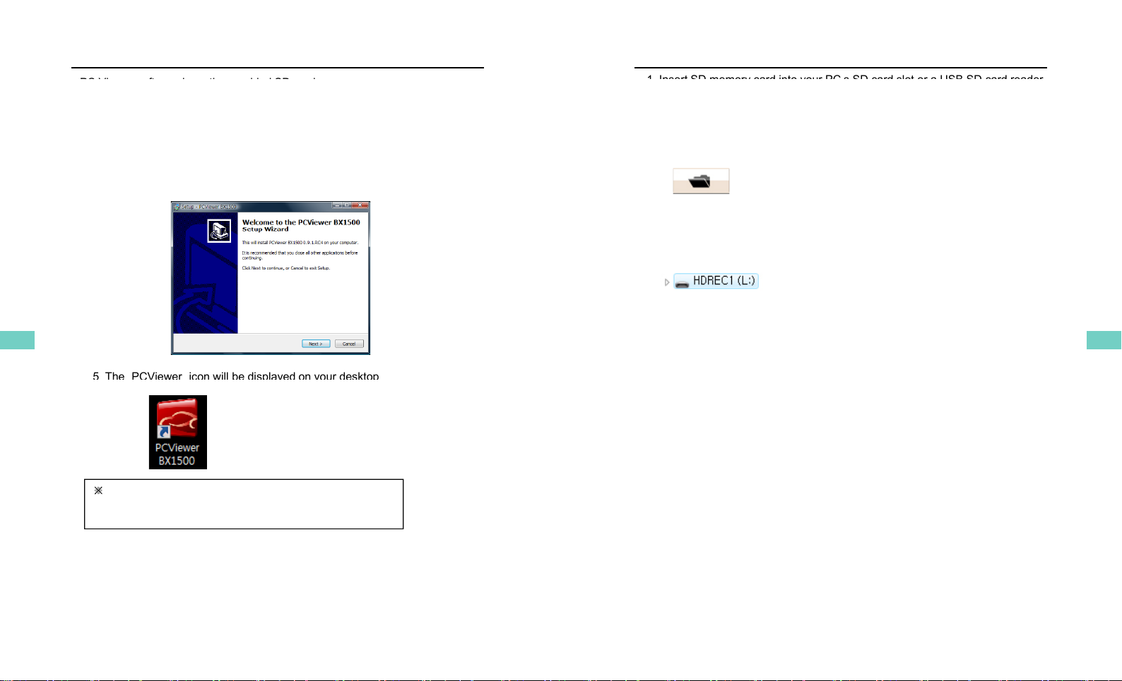
Note : PC Viewer software is pre-loaded on the SD card. Please ensure
h i t ll d th ft t PC b f f t th d
Built-in power backup (Super Capacitor)
When power to the unit is interrupted, BX1500Plus creates the last file using
the internal Super Capacitor.
BLUE LED (RECORD)
you
h
ave
i
ns
t
a
ll
e
d
th
e so
ft
ware
t
o your
PC
b
e
f
ore you
f
orma
t
th
e car
d
.
BLUE LED (RECORD)
The blue LED shows the power is on. The blue LED flash during the event recording.
RED LED (OVERWRITE)
The red LED will be turned on during overwriting.
Buzzer
8
Buzzer
“Beep” sound will occur when recording starts (this can be turned off at setup
page on PC viewer, if required) and to signal a system error.
OPERATION
1. Connect your vehicle’s power cable to the BX1500Plus after starting the
vehicle.
2. Blue LED & Red LED will be slowly blinking simultaneously and then
Blue LED will remain on. Blue LED li
g
ht means BX1500Plus is now
When Record Method set as “Event record”
g
ready for the event recording.
3. The event recording will automatically begin by G-sensor with one short
“Beep” sound.
4. The manual recording will start by pressing the [RECORD] button.
[
N
ot
i
ce]
M
u
l
t
i
p
l
e
im
pacts
co
v
e
r
age
[ ot ce] u t p e pacts co e age
Flash memory continuously captures the video data during the second or third
impact and record it to the first impact file.
1
C t hi l ’ bl t th BX1500Pl ft t ti th
When Record Method set as “Normal record”
1
.
C
onnec
t
your ve
hi
c
l
e
’
s power ca
bl
e
t
o
th
e
BX1500Pl
us a
ft
er s
t
ar
ti
ng
th
e
vehicle.
2. Blue LED & Red LED will be slowly blinking simultaneously and then
the Blue LED will remain on and flash every 5seconds.
3. Blue LED light flashing every 5 seconds means BX1500Plus is now
recording continuously.
recording
continuously.
4. The continuous recording(normal recording) will automatically begin just
after power on.
5. The manual recording that started by pressing the [RECORD] button or
the event recording by G-sensor make a event making in the continuous
recording file.
Take out SD memory card
Turn off the power and then check the BLUE LED light. Once the LED light
is off, take out the SD memory card.
Insert SD memory card
System Error Buzzer
“Beep” “Beep” sound will occur and the BLUE & RED LED light will blink
simultaneously when there is a system error or SD card is not inserted
Turn off the power and then check the BLUE LED light. Once the LED light
is off, insert the SD memory card.
9
simultaneously
when
there
is
a
system
error
or
SD
card
is
not
inserted
.
[Check the SD memory card when this occurs. To solve the problem, initialize
the SD card or replace the SD card.]
8 9

LIVE DISPLAY
To See Live Video Preview on LCD Monitor
1. Set your Video Out as NTSC or PAL. Refer to page 28.
2
C t id t bl f th BX1500Pl t it ith
2
.
C
onnec
t
your v
id
eo ou
t
ca
bl
e
f
rom
th
e
BX1500Pl
us
t
o a mon
it
or w
ith
component video input (yellow stereo cable).
Icons on Live display
GPS di t d
GPS
di
sconnec
t
e
d
GPS connected
Event Record Mode
Continuous(Normal) Record Mode
Overwrite Mode
One time Mode
Record (writing SD card)
10
SOFTWARE USER GUIDE
BX1500Plus PC Viewer Guide
[PC SYSTEM REQUIREMENT]
OS Windows 2000, Windows XP
Recommended PC specifications for PC Viewer software
Windows Vista, Windows 7
CPU Pentium4 2.6GHz or higher
RAM 512MB or higher
Interface SD Memor
y
Card Reader
If the PC does not meet the minimum system requirement the PC
y
HDD
Free space
Install 20MB or higher
Backup 2GB or higher
Display 1,024 x 768 pixel/High Color(16bit) or higher
11
If
the
PC
does
not
meet
the
minimum
system
requirement
,
the
PC
Viewer may not function properly.
10 11

INSTALLING PROCEDURES
PC Vi ft i th id d SD d
1. Insert the SD card into your PC (if your computer does not have
SD card slot, use the USB SD card reader) and open the “My Computer”
2. Right-click the “HDREC1” drive and select [Open]
PC
Vi
ewer so
ft
ware
i
s on
th
e prov
id
e
d
SD
car
d
.
3. Double click [SETUP.EXE] at [pcsw] folder.
4. Select the language and then follow the dialog box.
5 The
“
PCViewer
”
icon will be displayed on your desktop
5
.
The
PCViewer
icon
will
be
displayed
on
your
desktop
.
※NOTE: To Un-install the “PC Viewer BX1500”
Open the “Control Panel”
Select [Remove Program] and remove [PC Viewer BX1500]
12
Insert SD memory card
1 Insert SD memory card into your PC
’
s SD card slot or a USB SD card reader
1
.
Insert
SD
memory
card
into
your
PC s
SD
card
slot
or
a
USB
SD
card
reader
.
2. Run “PC Viewer BX1500”
3. Select [File] and then click “Select Data Folder” or Click [OPEN] button
[OPEN] button
4. Select SD memory card folder at the folder select window.
13
12 13

PC Viewer Setting
This setting is for the PC Viewer itself.
To set the Video Recorder (i.e. resolution, frame rate, etc. refer to page28).
[PC Viewer Setting] button
The ‘date’ formats and ‘speed’ unit will be set automatically according to the
PC Windows setting. However it can be changed with this PC viewer setting
menu.
Simple Mode
Check Simple Mode and press [OK] button.
Then PC Viewer skin will change to Simple Mode PC Viewer skin.
14
[Simple Mode PC Viewer]
When Record Method set as
“
Event record
”
Select file for playback
Ch k
“Switch” means
When Record Method set as Event record
Ch
ec
k
the event
“G-Senor” means
recording was
activated
recording was
activated by button
activated
by impact
Ch k ll fil
Blank means
previous event file is
more than 1 min
Load Button
When Record Method set as “Normal record”
Ch
ec
k
a
ll
fil
es
Button
more
than
1
min
.
Check
the file
Normal means
continuous
recording
The maximum
d ti i 3
d
ura
ti
on
i
s
3
minutes.
5 Check the event or normal recorded file from the list using mouse or
Load Button
Check all files
Button
5
.
Check
the
event
or
normal
recorded
file
from
the
list
using
mouse
or
click [Check All] button. Then click [Load] button.
15
14 15

FILE LOADING
6 Once click [Load] button the [FileList] tab will be changed to the [PlayList]
6
.
Once
click
[Load]
button
,
the
[FileList]
tab
will
be
changed
to
the
[PlayList]
tab as below
When Record Method set as “Event record”
Select file(s) to
playback
Return to the [FileList]
When Record Method set as “Normal record”
Select file(s) to
playback
Return to the [FileList]
16
Return
to
the
[FileList]
ICONS ON PLAYLIST
This file includes GPS data.
This file resolution is SXVGA (1280x960).
This file resolution is VGA (640x480).
This file recorded by G
Sensor
This
file
recorded
by
G
-
Sensor
.
This file recorded by Record button.
This file recorded by Normal (Continuous) record.
17
16 17

PLAYBACK SCREEN
When Record Method set as
“
Normal record
”
When Record Method set as Normal record
Display frame/Total frames number
Event area marking by G-sensor
or button (5 seconds per each event)
Google Map location
dt
Playback Icons Playback position indicator
d
a
t
a
This file recorded by Normal (Continuous) record.
This file resolution is SXVGA (1280x960).
This file recorded by Record button.
This file recorded by G-Sensor.
Post-recorded frame
Pre-recorded frame
This file resolution is VGA (640x480).
18
Continuously recorded frame
PLAYBACK
7. Click play button for playback.
Click & Drag the white bar to move the
playback position.
Volume & Brightness
Volume & Brightness
B f 20 d
Aft 20 d
Compass
Event
B
e
f
ore
20
secon
d
s
Aft
er
20
secon
d
s(Moving Direction)
Playback buttons
Pause
Next
Previous
X0.5, 1
Play X2, 4, 8, 16
Fast Forward
X0.5, 1
Reverse
X2, 4, 8, 16
Fast Reverse
Pause
Next
Image
Previous
Image
Single View
4x4 Multi View (Thumb
nail function)
Video up/down flip
4x4 Multi View (Thumb
-
nail function)
Zoom In G-sensor graph
Zoom Out G-sensor graph
Reset Zoom
Playback speed
19
Continuous playback next file Playback this file only
18 19

PLAYBACK
NOTE: PC Keyboard hot buttons
Function PC Ke
y
board hot buttons
y
1280x960 mode Enter
Return to the previous mode: Enter
Full screen mode Alt+ Enter
Return to the previous mode: Enter
Return
to
the
previous
mode:
Enter
Playback speed control Ctrl + F
0.5 => 1
Reverse playback speed control Ctrl + B
05
=
>1
0
.
5
>
1
Pause / Play Space
Previous Image →direction button.
Next Image ←direction button
[Remark] If the PC monitor resolution is less than 1280x960, 1024x768
mode will substitute1280x960mode.
20
Google maps
The route taken will be displayed on the Google maps at lower right
corner of the software UI.
To see the route & position on the Google map, the GPS data
should be recorded with video.
To see the map, the PC must be connected to the Internet.
The playback position will be shown on the map with an arrow.
The blue markings show the route taken.
Double click the blue mark to change the video playback position
to that point.
The camera icon indicates that there is a recorded file.
When the unit is set to Normal recording mode there is no
When the unit is set to Normal recording mode
,
there is no
route & camera icon on the map.
21
20 21

VIDEO ZOOM
HD Quality video image allows you to zoom in (up to x9) on a specific area.
Zoom in: Click mouse left button on
the screen
Zoom out (return to actual pixels):
Click mouse right button
Pic1. without zoom
Zoom in indicator
Pic2 2X zoom
Zoom
in
indicator
Pic2
.
2X
zoom
Zoom in indicator will be
displayed at the right bottom
corner when video zoom
function is activated by clicking
function
is
activated
by
clicking
mouse left button.
22
Pic2. 9X zoom
THUMB-NAIL FUNCTION
7. Click the button for 4x4 multi view (Thumb-nail function)
Click the thumbnail image to change the playback position.
Click right the mouse button to single image playback mode.
8. Click [Close] button to quit the playback.
Click [Close] to finish
the playback.
Then the [PlayList]
Then
the
[PlayList]
window will be changed
to the initial status.
23
22 23

Save as JPG & convert video to AVI file
9. Pause the playback and click ‘Save Image’ icon to make a JPG file.
‘Save Image’ icon
10. Click the ‘Save AVI’ icon to make an AVI file.
‘Save AVI’ icon
24
Printing an event report
Printer icon
11. Pause the playback and click the printer icon.
Type in the Title [Print Title] & any comments [Comment]
using the Keyboard.
The ‘Print Comment’ window allows up to 7 lines total.
25
24 25

Make Report
12. Click [Print] button in the print preview windows for printing.
The File Name [Print Title], Comment [Print Comment], G-sensor graph & map
will be printed on the first page.
Click [ 2x2 ] and then click [Print] to print 4 images per page
Click
[
2x2
]
and
then
click
[Print]
to
print
4
images
per
page
.
26
Backup Event/Log files
13. Click [Backup Event/Log files] icon to backup the files to the PC.
[Backup Event/Log files] icon
Select [Event data] or [Normal data] and select [Log data] first before
Select
[Event
data]
or
[Normal
data]
and
select
[Log
data]
first
,
before
clicking the [Backup Event/Log files] icon. Then the selected Event,
Normal, and Log data files are backed up on Windows to your preferred
destination.
To backup the entire SD card data to the PC, check [Backup All]
27
26 27

Drive Recorder Settings
14. Click [Recorder Setting] icon for setup.
[Recorder Setting] icon
Caution
Backup the SD
data first, before
clicking initializing
the SD card. The
old data is removed
when you save new
when
you
save
new
settings.
Record Method Event Record (Automatically starts Recording by G-
sensor event or Record Button)
Normal Record (Is always recording when powered
by 12/24V)
Record Mode Overwrite (The oldest data is overwritten when the
SD memory is full.)
SD
memory
is
full.)
One time (The recording stops automatically when
the SD memory is full.)
Resolution 1280x960(SXVGA), 640x480(VGA)
Frame Rate 640x480 Record su
pp
orts 1, 2, 3, 5, 10, 15, 30 f
p
s
pp p
1280x960 Record supports 1, 2, 3, 5, 10, 15 fps
Image Quality Super(better image quality), High
Recording Time Select event recording time here
Record audio
Check it to record Audio
Record
audio
Check
it
to
record
Audio
Video Out OFF, NTSC, PAL
28
Drive Recorder Settings
Vehicle ID Set vehicle ID and Driver name etc.
Up to 50 characters.
Beep on record “Beep” sound ON/OFF when Event recordings are started
G
tti
Ch k i l tti d d th h th
G
-sensor se
tti
ng
Ch
ec
k
s
i
mp
l
e se
tti
ng mo
d
e an
d
th
en c
h
ange
th
e
sensitivity. High sensitivity (8 or 9) means recording will
be started at very low impact.
Date/Time Automatically synchronize with GPS time. However
Manual time setting is also available.
Initialize SD card The SD configuration of the Drive Recorder will default to
the factory settings. All video and GPS data will be
deleted.
Delete record data All data will be deleted.
Caution
Once the record settings are changed all recorded data
Caution
Once
the
record
settings
are
changed
,
all
recorded
data
on the SD card will be removed.
Backup the recorded file first and then change the settings
Backup
the
recorded
file
first
and
then
change
the
settings
to avoid losing all recorded data.
29
28 29

Drive Recorder Settings
G-Sensor setting
If G-sensor sensitivity
value is high (8 or 9), it
may be too sensitive, it
will detect even a light
i t li htt IfG
i
mpac
t
or
li
g
ht
t
urn.
If
G
-
sensor sensitivity value
is a low setting (1 or 2),
it might not detect a
notable incident.
Sensitivity should be set
Sensitivity
should
be
set
in consideration of a
vehicle’s suspension and
also the road condition.
BX1500 Plus has an internal GPS supporting the automatic GPS Time
Synchronize function. The time recording is done based on UTC at the
BX1500Plus and automatically converts to the local time at the PC according
to the PC time zone setting when playing back using the PC Viewer.
So basically no need to change time here but if you hope to set time manually
use this menu.
If you use a NEW SD Memory card, initializing must be done first.
STEP1. Insert new SD memory card into
the PC.
STEP2. Run “PC Viewer BX1500”
STEP3. Select [ ] setting viewer program
and then click [Init SD card]
We recommend the [Init SD card] at least once per month to reduce the
possibility of any software errors
30
possibility
of
any
software
errors
.
Simple Mode Viewer
With thi ti th id i i i d d l f id i
With
thi
s op
ti
on,
th
e v
id
eo
i
s max
i
m
i
ze
d
an
d
a pane
l
o
f
v
id
eo prev
i
ews
appears in the right side.
Preview images
To change it to Normal Mode Viewer:
Click [Setting viewer program] icon
31
Un-check Simple Mode and press [OK]
30 31

15 Cli k [Ab t] i t h k th d t i f ti
Product Information
15
.
Cli
c
k
[Ab
ou
t]
i
con
t
o c
h
ec
k
th
e pro
d
uc
t
i
n
f
orma
ti
on.
About icon
32
LOG FILE PLAYBACK
16. Select [LOG] windows and then check the log from the log list using mouse
or click [Check All] button. Then click [Load] button.
Log data Log data will be recorded during driving even if there are no
events or video The maximum amount of log data saved is 60MB
The log
events
or
video
.
The
maximum
amount
of
log
data
saved
is
60MB
.
The
log
data overwrites the oldest data when 60MB is reached. Using this log data, we
can use the data sorting function which helps to find specific data or driving
behaviors, such as more than 80mph(or 80km) or 1G of X-axis force exceeded.
Search button
Input sorting data
G-sensor graph
GPS s
p
eed
,
G sensor X value
,
G sensor Y value
,
G sensor Z value
,
p,,,
,
Can each be checked first on the right side of each value. And then specify
the input data for data filtering.
If there is recorded video data, [Switch] or [G Sensor] a black dotted line
will be displayed on the graph.
G sensor X value: Front & Back (i e hard brake or quick acceleration)
33
G
sensor
X
value:
Front
&
Back
(i
.
e
.
hard
brake
or
quick
acceleration)
G sensor Y value: Left & Right (i.e sharp turn)
G sensor Z value: Up & Down (prominence and depression)
32 33

GPS LOG TO KML CONVERTER (for Google Earth)
To see the whole route on Google Earth, select a log file and click Google
Earth button.
STEP1 Install the Google Earth on your PC It is free of charge
Google Earth icon
STEP1
.
Install
the
Google
Earth
on
your
PC
.
It
is
free
of
charge
.
(http://earth.google.com/ )
STEP2. Check the log file
STEP3. Click Google Earth button
Then the route will be exported to Google Earth, which will
automatically launch.
34
Google Earth Cont’d
Google Earth lets you import the log data and save routes, add
place marks (i.e. customer pick up locations, or other points of interest),
add driving routes (to compare with the actual route taken, and it lets you
save it all within Google Earth for easy and free data management!
save
it
all
within
Google
Earth
for
easy
and
free
data
management!
You can view and download Goo
g
le Earth tutorials and user
g
uides here:
http://earth.google.com/support/bin/static.py?page=guide_toc.cs
gg
35
34 35

SPECIFICATIONS
Imagesensor 1/4"CMOSDigitalSensor1.2Mpixels
AngleofView BX1500Plus:120°(horizontal:88°,vertical:65°)
BX1500Plus170:170°(horizontal:131°vertical:96°)
Videoresolution 1280x960(SXVGA),640x480(VGA)
Framesper
second 30frames@640x480,15frames@1280x960
Recording By continuous,Byimpact,Byemergencybutton
Recordingtime before20(15,10)secafter20(15,10)sec,
Continuousrecording:Min65min~Max 148hours
GPS InternalGPS
G‐Sensor Internal3‐axisG‐sensor
Memory SD/SDHCflashmemorycard(support4GB,8GB,16GB,32GB)
RTC Internalbattery
Buzzer Recordingstart,error
LED 2LED(Record,Overwrite)
SuperCapacitor Enablerecordinglastfileandshutdown
PCsoftware PCViewer
Power input
12V
~
24V (cigarette plug)
Power
input
12V
24V
(cigarette
plug)
Power
consumption 2.8W
Size/Weight 80mmX50Ø,100g
O ti T
10
℃
~60
℃
O
pera
ti
on
T
emp. ‐
10
℃
~60
℃
36
RECORDING TIME TABLE
37
36 37
Table of contents
Other D-Teg Dashcam manuals