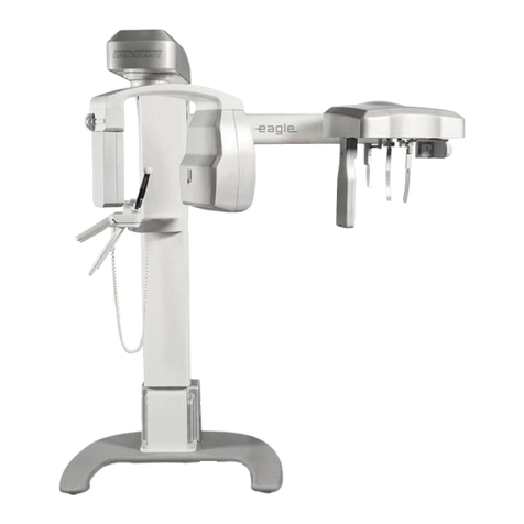
Dabi Atlante EAGLE 3D User manual

U
S
Mo
d
S
ER
’
d
el: Ea
g
’
S M
A
g
le 3D
A
NU
A
A
L

1
THIS PAGE WAS INTENTIONALLY
LEFT BLANK

2
TABLE OF CONTENTS
1.INTRODUCTION..................................................................................................................................7
2.SYMBOLS............................................................................................................................................8
3.WARNINGSANDPRECAUTIONS..........................................................................................................9
3.1.WARNINGSAND/ORCAUTIONDURINGTRANSPORTATIONANDSTORAGE...................................9
3.2.TRANSPORTATIONORSTORAGEENVIRONMENTALCONDITIONS..................................................9
3.3.OPERATIONALENVIRONMENTALCONDITIONS..............................................................................9
3.4.INSTALLEDEQUIPMENTCONDITIONSBETWEENOPERATIONS......................................................9
3.5.ADDITIONALPROCEDURESPRIORTOEQUIPMENTUSE................................................................10
3.6.WARNINGSAND/ORCAUTIONTOBEADOPTED...........................................................................10
3.6.1.WARNINGS AND/OR CAUTION DURING EQUIPMENT INSTALLATION.............10
3.6.2.WARNING AND/OR CAUTION DURING EQUIPMENT USE......................................10
3.6.3.WARNING AND/OR CAUTION AFTER EQUIPMENT USE/OPERATION................11
3.7.CAUTIONINCASEOFABNORMALEQUIPMENTFUNCTION..........................................................12
4.COMPUTERIZEDTOMOGRAPHYSYSTEMOVERVIEW........................................................................13
4.1.DIGITALPAN‐CBCTCONFIGURATION............................................................................................13
4.2.DIGITALPAN‐CBCT‐CEPHCONFIGURATION..................................................................................14
4.3.DIGITALSNAP‐ONCONFIGURATION.............................................................................................15
4.4.DIGITALFIXEDCONFIGURATION...................................................................................................16
4.5.ANALOGCONFIGURATION............................................................................................................17
4.6.POWERSUPPLYUNITOPTIONS.....................................................................................................18
4.7.FREESTANDINGBASE(OPTIONAL)................................................................................................18
4.8.LISTOFACCESSORIES.....................................................................................................................19
5.COMPUTERSYSTEM..........................................................................................................................21
5.1.RECOMMENDEDSPECIFICATIONS.................................................................................................21
5.2.NETWORKADAPTERCONFIGURATION.........................................................................................21
5.3.SOFTWAREINSTALLATION............................................................................................................24
6.IMAGINGPROGRAMS.......................................................................................................................28
6.1.PANORAMICPROFILES:.................................................................................................................28
6.2.CEPHALOMETRICPROFILES...........................................................................................................30
6.1.TOMOGRAPHYPROFILE.................................................................................................................31
7.CONTROLPANEL...............................................................................................................................32

3
7.1.INTRODUCTION.............................................................................................................................32
7.2.MAINSCREEN................................................................................................................................32
7.3.CONTROLKEYS..............................................................................................................................37
7.4.CONTROLPANELINDICATINGLIGHTS...........................................................................................39
7.5.REMOTEEXPOSURESWITCH(OPTIONAL).....................................................................................39
8.PREPARINGFORTHEEXPOSURE.......................................................................................................40
8.1.TURNINGTHEEQUIPMENTON.....................................................................................................40
8.2.BEFOREPOSITIONINGTHEPATIENT..............................................................................................41
8.3.RECOMMENDATIONSFORPEDIATRICEXAMINATIONS................................................................41
9.PANORAMICEXPOSURES..................................................................................................................45
9.1.GETTINGTHESOFTWAREREADY..................................................................................................46
9.2.POSITIONINGTHEPATIENT...........................................................................................................47
9.3.TAKINGAPANORAMICEXPOSURE................................................................................................48
9.4.ETTINGSANDDOSEINFORMATION..............................................................................................50
10.CEPHALOMETRICEXPOSURE.............................................................................................................51
10.1.GETTINGTHESOFTWAREREADY..................................................................................................51
10.2.POSITIONINGTHEPATIENT...........................................................................................................52
10.3.TAKINGACEPHALOMETRICEXPOSURE.........................................................................................53
10.4.SETTINGSANDDOSEINFORMATION.............................................................................................54
11.TOMOGRAPHY..................................................................................................................................56
11.1.GETTINGTHESOFTWAREREADY..................................................................................................56
11.2.POSITIONINGTHEPATIENT...........................................................................................................57
11.3.TAKINGATOMOGRAPHICEXPOSURE...........................................................................................59
11.4.SETTINGSANDDOSEINFORMATION.............................................................................................60
12.PROCEDURESFORREUSE..................................................................................................................62
12.1.CLEANING......................................................................................................................................62
12.2.DISINFECTION................................................................................................................................62
13.TROUBLESHOOTINGGUIDE..............................................................................................................63
13.1.UNITOPERATIONPROBLEM..........................................................................................................63
13.2.PATIENTPOSITIONINGPROBLEM1................................................................................................64
14.QUALITYASSURANCE.......................................................................................................................70
14.1.INITIALPROCEDURE......................................................................................................................71
14.2.QADIAGNOSISFORPANORAMIC..................................................................................................73
14.2.1.BEAM POSITION.............................................................................................................73

4
14.2.2.CALIBRATION.................................................................................................................74
14.2.3.MAXIMUM CONTRAST RESOLUTION.....................................................................75
14.3.QADIAGNOSISFORCEPHALOMETRIC...........................................................................................76
14.3.1.BEAM POSITION.............................................................................................................76
14.3.2.CALIBRATION.................................................................................................................76
14.3.3.MAXIMUM CONTRAST RESOLUTION.....................................................................77
14.4.QADIAGNOSISFORTOMOGRAPHY...............................................................................................79
14.4.1.PREPARING X-RAY UNIT.............................................................................................79
14.4.2.CONTRAST SCALE.........................................................................................................80
14.4.3.NOISE AND UNIFORMITY............................................................................................80
14.4.4.SLICE THICKNESS.........................................................................................................81
14.4.5.HIGH CONTRAST SPATIAL RESOLUTION..............................................................81
14.4.6.LOW CONTRAST DETECTABILITY..........................................................................82
14.5.DOSEMEASUREMENT...................................................................................................................82
14.6.QAREPORT....................................................................................................................................84
15.INSTALLATION,INSPECTIONANDMAINTENANCE............................................................................85
15.1.INSTALLATION...............................................................................................................................85
15.2.PERIODICINSPECTION...................................................................................................................85
15.3.PREVENTIVEMAINTENANCE.........................................................................................................86
15.4.CORRECTIVEMAINTENANCE.........................................................................................................86
16.DISPOSALOFTHEUNIT.....................................................................................................................87
16.1.ENVIRONMENTALCONTAMINATION............................................................................................87
17.TECHNICALSPECIFICATIONS.............................................................................................................88
17.1.REGULATORYINFORMATION........................................................................................................88
17.2.GENERALINFORMATION...............................................................................................................88
17.3.RADIOLOGICALINFORMATION......................................................................................................89
17.4.X‐RAYGENERATOR........................................................................................................................90
17.4.1.SPECIFICATIONS...........................................................................................................90
17.4.2.CHARACTERIZATION..................................................................................................90
17.5.X‐RAYTUBE....................................................................................................................................91
17.5.1.SPECIFICATIONS...........................................................................................................91
17.5.2.TUBE CHARACTERIZATION.......................................................................................91
17.6.EQUIPMENTTESTEDACCORDINGSTANDARDS............................................................................93
17.7.MAXIMUMSYMMETRICALRADIATIONFIELD...............................................................................97
17.7.1.IRRADIATED FIELD SIZE – ANALOG AND DIGITAL PANORAMIC EXAM
(PAN: ADULT AND CHILD – TMJ – MAXILLARY SINUS)........................................................97
17.7.2.IRRADIATED FIELD SIZE – DIGITAL CEPH EXAM:.............................................97
17.7.3.IRRADIATED FIELD SIZE – ANALOG CEPH - LATERAL EXAM.......................98
17.7.4.IRRADIATED FIELD SIZE – ANALOG CEPH - FRONTAL EXAM.......................98
17.7.5.IRRADIATED FIELD SIZE – TOMOGRAPHIC EXAM:...........................................99
17.8.ELECTROMAGNETICEMISSIONS..................................................................................................100

5
17.9.ELECTROMAGNETICIMMUNITY..................................................................................................100

18.IDENTIFICATIONLABELS.................................................................................................................104
18.1.PACKAGE.....................................................................................................................................104
18.2.PRODUCT.....................................................................................................................................105
19.EQUIPMENTDIMENSIONS..............................................................................................................106
20.WARRANTY.....................................................................................................................................107

6
Attention
For greater safety:
Read and understand all instructions written in this manual before installation or use of
the equipment.
This instruction manual should be read by all operators of the equipment.
This instruction manual was originally written in Portuguese.
Intended Use
Intended for dental radiographic examination and diagnosis of diseases of the teeth,
jaw and oral structures.
Warning Statement
Only personnel authorized by Alliage are qualified to install and service this
equipment. Any attempt to install or service this equipment by anyone not so authorized
will void the warranty.
It is imperative that this equipment be installed, serviced, and used by personnel
familiar with the precautions required to prevent excessive exposure to both primary and
secondary radiation. This equipment features protective designs for limiting both the
primary and secondary radiation produced by the X-ray beam. However, design features
cannot prevent carelessness, negligence, or lack of knowledge.
Alliage requires anyone moving or transporting their machine to contact the service
network Alliage.

7
1. INTRODUCTION
The Eagle 3D Machine is a complete 3-in-1 system for dental imaging capable of:
Analog Panoramic Profiles
Analog Cephalometric Profiles
Digital Panoramic Profiles
Digital Cephalometric Profiles
CBCT Profiles
The digital machines use a digital sensor and auto image processing that allow a
speed up the diagnostic and improve the clinic workflow.
The configuration 3D use a Cone beam Computed Tomography.
The equipment has three movement axes (two in orthogonal directions and one
rotational) making it possible to execute elaborate imaging profiles.
It features a complex profile movement around the dental arch and radiographic
emission compensation in the spinal region, when necessary reconstructing the dental arch
into a plane image. Each individual profile prioritizes a set of characteristics improving
diagnostic capabilities. For example, the standard panoramic prioritizes image layer width,
constant vertical magnification and homogeneous exposure along the whole image.
Likewise, the low dosage profile prioritizes the reduction of dosage (time and anodic
current).
The profiles can be applied to a variety of patients: adult or child; small, medium or
large. The equipment has predefined exposure parameters depending on patient type.
However, the user can apply whatever is best for the situation.
The user interface is composed of a control panel located close to the patient chin
rest and an exposure switch. A remote exposure switch installed outside the radiation room
is optional. The exposure switch is a dead-man type switch.
Ease of patient positioning is complimented by the patient entry into the machine
from the side.There are three lasers available for positioning: Mid-Sagittal plane, Frankfurt
Plane and Image Layer Plane (canine). These features make it possible for the user to
precisely position the patient.
For patient comfort, a demonstration mode is also available making it possible to
inform the patient of the procedure prior to exposure.

2.
S
S
YMBO
L
Use the i
c
"
F
L
o
It
c
a
fa
"
P
L
o
It
p
r
d
u
"
T
L
o
It
h
a
"
L
o
It
b
o
tr
a
"
T
L
o
It
b
e
st
"
L
o
It
p
r
d
u
"
H
L
o
It
o
f
st
"
G
L
o
c
e
si
n
"
D
L
o
th
in
"
D
e
li
m
"
W
a
n
It
ta
th
th
L
S
c
ons below
F
ra
g
ile"
o
cated on the p
a
determines tha
t
a
refully transpo
r
lls or shock
P
rotect a
g
a
i
o
cated on the p
a
determines tha
t
r
otected agains
u
ring transporta
t
T
his side u
p
o
cated on the p
a
determines t
h
a
ndled with the
a
Maximum
p
o
cated on the p
a
determines th
e
o
xes that can
a
nsportation an
d
T
emperatur
e
o
cated on the p
a
determines
e
tween which
t
ored or transpo
r
Protect fro
m
o
cated on the p
a
determines tha
t
r
otected again
s
u
ring the transp
o
H
umidit
y
li
m
o
cated on the p
a
determines th
e
f
humidity dur
orage
G
ravit
y
cen
t
o
cated on the p
e
nter of gravity
n
gle unit is mo
v
D
o not step
o
cated on the
at it is forbidde
n
dicated area
Operatin
g
T
e
termines the
m
it
W
EEE -Was
t
n
d electron
i
indicates that
ken to a speci
a
e end of its us
e
e device and th
to identif
y
a
ckaging side.
t
the equipment
r
ted, thus preve
n
i
nst moistu
r
a
ckaging side.
t
the equipment
s
t any type of
t
ion and storag
e
p
"
a
ckaging side.
h
at it must b
e
a
rrow pointing
u
p
ilin
g
"
a
ckaging side.
e
maximum n
u
n
be piled u
p
d
storage.
e
limit"
a
ckaging side.
the temperat
u
t
he packaging
rted.
m
direct su
n
a
ckaging side.
t
the equipment
s
t exposure to
o
rtation and sto
m
it "
a
ckaging side.
e
upper and l
o
ing transporta
t
t
er"
ackage. It indi
c
of the containe
r
v
ed.
on"
packaging. It
i
n
to step on or
c
T
emperatur
e
operating te
m
te of electri
c
i
c equipme
n
the product
m
a
l waste dispos
a
e
ful life. It applie
e accessories.
8
the s
y
mbol
s
must be
n
ting
r
e"
must be
moisture
e
.
e
always
u
pwards.
u
mber of
p
during
u
re limit
must be
n
li
g
ht "
must be
sunlight
rage.
o
wer limit
t
ion and
c
ates the
r
when a
i
ndicates
c
limb the
e
"
m
perature
c
al
n
t"
m
ust be
a
l site at
s to both
s
on
y
our e
q
q
ui
p
ment.
"
Type-
"
A
tten
t
"
G
ene
r
"
A
ctio
n
"
Ionizi
n
Indicates
of ionizin
g
" Ionizi
n
It indicate
of ionizin
g
"Focal
S
"Laser
"Hi
g
h
V
" Prote
c
It indicate
s
"Manuf
a
B Applied
P
t
ion"
r
al warnin
g
"
n
required"
ng
Radiatio
n
the emission o
r
g
radiation.
ng
Radiatio
n
e
s the current o
r
g
radiation
S
pot"
Diode Li
g
ht
V
olta
g
e"
c
tive
g
roun
d
s
the protective
f
acture"
P
art"
n
Emission
"
r
imminent emi
s
n
"
r
potential pres
e
Emitter"
d
"
ground termin
a
"
s
sion
e
nce
a
ls

9
3. WARNINGS AND PRECAUTIONS
3.1. WARNINGS AND/OR CAUTION DURING TRANSPORTATION AND
STORAGE
The equipment must be transported and stored by observing the following:
Care should be taken to prevent falls and impact.
The arrows must be pointing upwards.
Do not stack.
Protect against moisture, rainwater aspersion and wet ground.
This equipment must be unpacked and installed by an authorized technician.
Premature unpacking does not generate safety risks, but leads to the equipment warranty
voidance.
3.2. TRANSPORTATION OR STORAGE ENVIRONMENTAL CONDITIONS
Environmental temperature range for
transportation and storage
0ºC to +55ºC (+32°F to
131°F)
Transportation and storage relative humidity
range
30% to 75%
(non condensing)
Atmospheric pressure range 700 hPa to 1060 hPa
(525 mmHg to 795 mmHg)
3.3. OPERATIONAL ENVIRONMENTAL CONDITIONS
Operation ambient temperature range +18°C to +25°C
(+64.4°F to 77°F)
Ambient temperature range recommended +21°C a +26°C
(69.8°F to 78.8°F)
Operation relative humidity range 30% to 75%
(non condensing)
Atmospheric pressure range 700 hPa to 1060 hPa
(525 mmHg to 795 mmHg)
3.4. INSTALLED EQUIPMENT CONDITIONS BETWEEN OPERATIONS
Storage ambient temperature range +5°C to +45°C
(+41°F to 113°F)
Ambient temperature range recommended by
manufacturer
+15°C a +30°C
(+59°F to 86°F)
Storage relative humidity range 30% to 75% (non-condensing)
Atmospheric pressure range 700 hPa to 1060 hPa
(525 mmHg to 795 mmHg)

10
3.5. ADDITIONAL PROCEDURES PRIOR TO EQUIPMENT USE
Even prior to its first use, the equipment must be cleaned and disinfected; the same
additional procedures must be followed for reuse, as described in Chapter 12.
3.6. WARNINGS AND/OR CAUTION TO BE ADOPTED
3.6.1. WARNINGS AND/OR CAUTION DURING EQUIPMENT INSTALLATION
The equipment must be installed only by service technicians authorized by the
manufacturer.
Place the equipment on a site where it will not be in contact with moisture or
water.
Install the unit on a site where it will not be damaged by pressure, temperature,
moisture, direct sunlight, dust or salts.
The equipment must not be submitted to inclination, excessive vibration or shock
(including during transportation and handling).
This equipment has not been designed for use in facilities where vapors,
flammable anesthetic mixtures in contact with air, oxygen or nitrous oxide can be
detected.
Check the equipment’s voltage when performing electric installation. Failure to
do so may damage the equipment.
The equipment must be properly grounded. Failure to do so may result in
“Safety Hazard”.
Depending on local regulation the X-Ray emission control may require
installation outside the facility where the equipment is placed, and the operator
may need visual contact with the patient through a window with radiological glass
or similar, since the operator must not lose visual contact with the patient.
Mobile and portable RF communication equipment can affect the Eagle 3D
Computerized Tomography Machine.
This equipment must be solely used by health care professionals as it may cause
radio interference or interrupt the operation of nearby equipment. Mitigatory
measures, such as equipment re-orientation or replacement and the facility’s
screening, may be necessary.
3.6.2.WARNING AND/OR CAUTION DURING EQUIPMENT USE
The equipment must be operated only by qualified and trained professionals
(dentists, radiology technicians, hygienists or engineers).
Always observe the display messages, the equipment as a whole and the
patient in order to detect any arising problems early.
In case occasional maintenance is required, use only services provided by
Authorized Service Technicians.
The equipment has been designed to withstand continual and intermittent
operation; therefore, follow the cycles described in these operation
instructions.

3.6.3
Si
n
re
c
ro
o
be
A
l
co
ot
h
in
t
NO
T
WO
M
THE
. WARNI
N
T
u
p
e
A
l
If
au
D
o
co
T
h
el
e
A
f
co
n
ce radiat
i
c
ommende
d
o
m, unless
p
ro
p
erl
y
pr
l
thou
g
h thi
s
m
p
atibilit
y
h
er e
q
ui
pm
t
erference
o
T
RECOMM
M
EN.
E
MANUFA
C
THE X-
R
THOSE
DAMA
G
A
ND/O
R
A
ND M
A
THE O
P
EQUIP
M
IMPRO
P
N
G AND/O
R
u
rn off the
riods of ti
m
l
wa
y
s kee
p
t
the e
q
ui
pm
u
thorized te
c
o
not re
p
la
c
nnections
u
h
e Ea
g
le 3
D
e
ctric scal
pe
f
ter usin
g
t
h
ntact with t
h
i
on ex
p
os
u
d
that no o
the
p
atient
r
otected a
ga
s
e
q
ui
p
me
n
standards,
i
m
ent. Do n
o
o
r with devi
c
ENDED T
H
C
TURER S
H
R
AY MAC
H
FOR WHI
C
G
E CAUSE
D
R
PATIENT
A
INTENAN
P
ERATION
M
ENT.
P
ER EQUI
P
R
CAUTI
O
x-ra
y
mac
h
m
e.
t
he e
q
ui
p
m
e
m
ent is def
e
c
hnical assi
s
c
e an
y
e
q
u
i
u
nnecessaril
y
D
CBCT M
a
e
l or other s
i
h
e e
q
ui
p
me
n
h
e
p
atient.
11
u
re can c
a
ne should
re
q
uires re
s
a
inst X-
R
a
y
n
t has bee
n
i
t ma
y
, und
e
o
t use it
w
c
es that cre
a
H
E USE OF
H
ALL NOT
H
INE IS US
E
C
H IT HAS
B
D
TO THE
E
T
AS A RES
CE PROC
E
INSTRUC
T
P
MENT OP
E
O
N AFTE
R
h
ine's mas
t
e
nt clean fo
r
e
ctive, do
n
s
tance.
ip
ment
p
ar
t
y
.
a
chine mus
t
i
milar devi
c
n
t, clean an
d
a
use dam
a
remain in
t
s
traint. In t
h
emission.
n
desi
g
ned
e
r ver
y
extr
w
ith other
d
a
te hi
g
h ele
c
X-RAY E
Q
BE LIABL
E
E
D FOR P
U
B
EEN DES
E
QUIPME
N
S
ULT OF I
M
E
DURES IN
T
IONS ACC
E
RATION.
R
EQUIPM
E
t
er switch
w
r its next o
p
n
ot tr
y
to fi
t
s. Do not
d
t
be off wh
e
c
es are bein
g
d
disinfect
a
ag
e to hu
t
he radio
g
r
a
h
is case, su
c
accordin
g
t
eme condit
i
d
evices th
a
c
troma
g
net
i
Q
UIPMENT
F
E
IN CASE
:
U
RPOSES
O
IGNED.
N
T, THE OP
M
PROPER I
N
DISAGRE
E
OMPANYI
N
E
NT USE/
O
w
hen it is
p
eration.
x it
y
ourse
d
isconnect
e
n other e
qu
g
used.
a
ll
p
arts tha
t
man cells
,
ap
hic exa
m
c
h individu
t
o electro
m
i
ons, interf
e
a
t are sens
i
i
c disturban
c
F
OR PRE
G
:
O
THER TH
A
ERATOR
N
STALLA
T
E
MENT WI
T
N
G THE
O
PERATI
O
not used f
o
lf, instead
c
the cable
o
u
i
p
ment su
c
t
ma
y
have
,
it is
m
ination
al must
m
a
g
netic
e
re with
i
tive to
c
es.
G
NANT
A
N
T
ION
T
H
O
N
o
r lon
g
c
all for
o
r other
c
h as an
been in

12
3.7. CAUTION IN CASE OF ABNORMAL EQUIPMENT FUNCTION
In case the equipment shows abnormal heating, noise or any other type of
abnormality, check if the problem is related to any of the items listed in this manual. If the
problem cannot be solved, turn off the equipment and call for Authorized Technical
Assistance. Use the website http://eagle-image.com or call Customer Service at telephone
number: +55 (16) 3512-1242.

4.
C
4.
T
C
OMPU
T
1.DIGITA
L
T
he followi
n
Con
t
Patient
X-Ra
y
T
ERIZ
E
L
PAN-CB
n
g image s
h
t
rol Panel
Handles
y
Tube Hea
d
Mov
Mech
a
E
D TOM
O
CT CONF
h
ows the w
h
ing
a
nis
m
13
O
GRA
P
IGURATI
O
h
ole system
P
HY SY
S
O
N
without op
t
H
S
TEM
O
t
ional Ceph
Rotati
n
Pan
S
Senso
r
H
ea
d
Holder
Column
C
S
e
O
VERVI
E
h
arm moun
t
n
g Ar
m
Bas
e
S
enso
r
r
Holde
r
C
BCT Senso
r
e
nsor Holde
r
E
W
t
ed.
e
(optional)

4.
T
Control Pan
e
Pati
e
X-Ray
T
Head
Mo
v
Mech
a
2.DIGITA
L
T
he followi
n
e
l
e
nt Handles
T
ube
v
ing
a
nis
m
L
PAN-CB
n
g image s
h
CT-CEPH
h
ows the w
h
14
CONFIG
U
h
ole system
CB
C
H
Head Su
p
U
RATION
with optio
n
Rotati
n
Base (
o
C
T Sensor
H
older
p
port
Column
Pan
S
Ho
l
n
al Ceph ar
m
n
g Ar
m
o
ptional)
Secon
d
Collim
a
S
ensor
l
der
m
mounted.
Cep
h
No
d
ary
a
to
r
Ear Rods
h
alostat
Cep
h
H
se Support
h
Senso
r
H
olde
r

Control
P
P
a
X-Ray
T
Head
R
M
4.
P
anel
a
tient Handles
T
ube
R
otating Ar
m
Moving
M
echanis
m
3.DIGITA
L
The foll
o
T
H
L
SNAP-
O
o
wing imag
e
H
E SECON
O
N CONFI
G
e
shows the
D SENSO
R
H
15
G
URATIO
N
whole syst
e
R
IS OPTIO
N
SNAP-O
N
Cep
h
H
ead Support
N
e
m with op
t
N
AL
N
Senso
r
h
alostat Arm
t
ional Ceph
Ce
p
Base (o
p
Second
a
Collima
t
Col
u
arm mount
e
p
halostat (Op
t
p
tional)
a
ry
t
o
r
Nose S
u
u
mn
e
d.
t
ional)
S
N
Sen
s
Ear rods
u
pport
N
AP-ON
s
or Holde
r

4.
this
c
4.DIGITA
L
The foll
o
c
onfiguratio
Control
P
Pa
X-Ray T
u
Head
R
M
L
FIXED
C
o
wing imag
e
n.
P
anel
tient Handles
u
be
R
otating Ar
m
Moving
M
echanis
m
C
ONFIGU
R
e
shows th
e
16
R
ATION
e
whole sys
t
t
em. No op
t
H
t
ional ceph
SNAP-O
N
ead Support
arm is avai
l
N
Senso
r
l
able in
Base (o
p
Col
u
p
tional)
u
mn

Cont
X-R
a
Hea
d
4.
t
rol Panel
Patient Han
d
a
y Tube
d
Rotating A
r
Moving
Mechanis
m
5.ANALO
The foll
o
d
les
rm
m
G CONFI
G
o
wing imag
e
G
URATIO
N
e
shows the
17
N
whole syst
e
Fil
m
C
Head Supp
o
e
m with op
t
m
Holde
r
C
ephalostat A
r
o
rt
t
ional Ceph
Base
r
m
C
arm mount
e
Cephalostat
(
(optional)
Nos
e
C
olumn
e
d.
(
Optional)
Ear ro
d
e
Support
Film
Holder
d
s

4.
T
conf
i
*Ord
e
4.
T
T
insta
l
6.POWE
R
T
he followi
n
i
gurations.
e
r on request
7.FREE S
T
he followi
n
T
he equipm
e
l
lation.
R
SUPPLY
n
g image s
h
Standard*
TANDING
n
g image sh
o
e
nt will be
UNIT OP
T
hows the
P
BASE (O
o
ws the opt
fixed to th
e
18
T
IONS
P
ower Sup
p
PTIONAL
)
ional Free
S
e
base and
p
ly Unit o
p
)
S
tanding B
a
wall by a
n
p
tions that
c
Slim
a
se.
n
authorize
d
c
an be use
d
d
technician
d
in all
during

4.
8.LIST O
F
F
ACCES
S
1
2
3
4
5
6
7
8
S
ORIES
1
Bite
G
2
Silico
n
3
Chin r
e
4
Chin r
e
5
TMJ a
n
6
Chin r
e
7
Head
H
8
Head
H
19
G
uide
n
chin rest c
e
st for CT
e
st for pati
e
n
d Sinus n
o
e
st for pati
e
H
older acry
l
H
older
c
over
e
nt with tee
t
o
se suppor
t
e
nt without
t
l
ic bars
t
h
t
eeth
Other manuals for EAGLE 3D
1
Table of contents
Other Dabi Atlante Dental Equipment manuals

Dabi Atlante
Dabi Atlante Bellagio User manual

Dabi Atlante
Dabi Atlante EAGLE User manual

Dabi Atlante
Dabi Atlante Spectro 70X Series User manual

Dabi Atlante
Dabi Atlante PROFI NEO User manual

Dabi Atlante
Dabi Atlante COBRA CONTRA ANGLE Series User manual

Dabi Atlante
Dabi Atlante Syncrus G3 User manual

Dabi Atlante
Dabi Atlante RAIOS X Spectro 70X User manual

Dabi Atlante
Dabi Atlante EAGLE 3D User manual

Dabi Atlante
Dabi Atlante COBRA CONTRA ANGLE INTRA 32 CA User manual

Dabi Atlante
Dabi Atlante MICRO MOTOR INTRA 32MM C SPRAY TB User manual