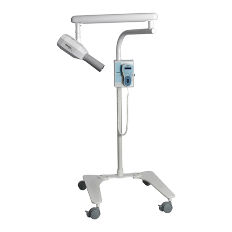
Dabi Atlante Spectro 70X Series User manual


2
PRESENTATION OF MANUAL
INSTRUCTIONS FOR USE
ATTENTION
Technical Name: Dental X Ray Device
Trade Name: Raios-X
Brand: Dabi Atlante
Trade models:
• Spectro 70X Coluna Móvel
• Spectro 70X Parede
• Spectro 70X Pantográco Coluna Móvel
• Spectro 70X Pantográco Parede
• Spectro 70X Pantográco Piso
• Spectro 70X Piso
Manufacturer/ Distribuitor:
Alliage S/A Indústrias Médico Odontológica
C.N.P.J. 55.979.736/0001-45 - Insc. Est. 582.002.897.114
Rod. Abrão Assed, Km 53+450m - Cx. Postal 782 CEP 14097-500
Ribeirão Preto - S.P. - Brasil
Telefone +55 (16) 3512-1212
Technical Duties: Daniel R. de Camargo
CREA-SP: 5062199650
Registration ANVISA #: 10069210087
For greater safety:
Read and understand all the instructions contained in these instructions for use before installing
or operating this equipment.
Note: These instructions for use must be read by all the operators of this equipment.

3
INDEX
02 PRESENTATION OF MANUAL
04 IDENTIFICATION OF EQUIPMENT
06 MODULES, ACCESSORIES, OPTIONS AND MATERIALS OF CONSUMPTION
08 TECHNICAL SPECIFICATIONS
08 General features
11 Cooling
11 Thermal protection
11 Protection against acidental activation
11 Under current protection
11 Overvoltage Protection
11 Undervoltage Protection
11 Trigger
12 Protection by distance against parasite radiation
12 How to regulate the arm tension
12 Radiation quality
14 Transmitter assembly
15 Dimensions
20 Packing symbols
20 Product symbols
28 INSTALLATION OF EQUIPMENT
30 OPERATION OF EQUIPMENT
35 PRECAUTIONS, RESTRICTIONS AND WARNINGS
35 Recommendations for preserving the equipment
35 Transportation, storage and operation
35 Sensibility to predictable environmental conditions in regular use conditions
36 Precaution and warnings “during the installation” of the equipment
36 Precautions and warnings “during the use” of equipment
37 Precautions and warnings “after” the use of equipment
37 Precautions and warnings during the “cleaning and disinfection” of equipment
37 Precautions in case of alteration in the functioning of equipment
37 Precautions to be adopted against foreseeable or uncommon risks, related to the deactivation
and abandoning of equipment
38 CORRECTIVE AND PREVENTIVE MAINTENANCE AND PRESERVATION
38 Additional procedures for reuse
38 Cleaning
38 Disinfection
39 Preventive Maintenance
39 Corrective Maintenance
40 UNFORESEEN EVENTS – SOLUTION OF PROBLEMS
41 EQUIPMENT’S WARRANTY
41 FINAL CONSIDERATIONS

4
IDENTIFICATION OF EQUIPMENT
Dear Customer
This manual is a general presentation of your product and it will give you important details to help
you to solve possible problems.
Please, read it and keep this with you.

5
Description of Equipment
This device is for intraoral radiography of patient’s dentition with the purpose of making a diagnostic.
It is a unit of X- Ray for odontological use, with nominal tension of 70kVp and current in the tube of
7,0 mA. It has a centesimal digital timer, particularly developed for using with digital radiographic
sensors, it reduces the time of radiation exposure and also it is indicated for conventional radiographic
lms.
Fixed column with the option of mobile column with 4-caster base; super steady columns, painted
in epoxy at 250º C, and option of base for mounting on the wall built in steel, painted in epoxy and
covered by a cover in polystyrene of high impact.
It is composed of type-pantographic arm (when pantographic model), which allows better reach
and use in many positions.
Tube (ampoule), with focal point of 0,8 x 0,8mm, ltration with aluminum equivalence of 3,22
mm, cylindrical guide made in radiopaque polymer in order to avoid secondary radiations, wound
completely immersed in special oil.
Manual trigger at a distance of 5m. Duly tested by legal body, respecting the rules in eect of
radiological protection and elaborated by National Nuclear Energy Commission - CNEN.
The test method for measuring tension parameters of mean peak in the x- ray tube (kVp), mean
current in the x-ray tube (mA), application time of load on x-ray tube(s) and product current X
time in the x-ray time (mAs), adopted is the following:
It is used for measuring the device Dynalyzer III digital display, connected to a high tension unit.
This unit consists of a resistive tension divisor of 1:20.000.
For odontological x-ray equipment it is used an adapter system in order to make a connection of
the device Dynalyzer III. “In order to check the results obtained, it is connected to high tension unit
The digital storage oscilloscope 2230 produced by Tektronix which gives the possibility to store an
electrical signal to which is subject the x-ray tube, thus allowing an inspection of mean peak in
the x-ray tube and the application time of load. Such results can be compared with those obtained
from Dynalyzer III”.
Principles and fundamentals applied to the product functioning
Photomultipliers set, which are generated in X-rays tubes that transform light energy into electric
energy, and then a circuit set forms the image, in order to diagnose or to guide evasive medical
procedures and dental treatments.
Indication of Equipment
This equipment is for dental use use only. It must be operated and utilized by specialized professional
(certied professional, according to the legislation of the country) and following the instructions of
the manual. The operation of the equipment required, for the professional, the utilization of correct
instruments and it should to be in perfect conditions of the use, and to protect the professional, the
patients and others, in the eventual danger situation.
IDENTIFICATION OF EQUIPMENT
6
01 - Radiation transmitter Assembly x (cylinder head)
02 - Graduated scale
03 - Pantographic Arm
04 - Fixed arm (type Floor)
4A - Fixed arm (type Wall)
05 - Electronic command
5A - Electronic command (type Wall)
06 - Main switch - On / O
07 - Fuse box
08 - Distance Control with cable
09 - Column
10 - Power - in cable
11 - Base (mobile type)
12 - Wheels
13 - Base (xed type)
*14 - Smaller colimator rectangular kit
*15 - Extension with colimator cone kit
The contents of this page are of an informative
nature, the equipment being able to dier from
that illustrated. So, upon acquiring the product
check the technical compatibilty between
equipment, coupling and accessories.
MODULES, ACCESSORIES, OPTIONS AND MATERIALS OF CON-
SUMPTION
14 15
05
03
03
03
02
02
02
06
01
01
01
11
12
10 10
13
09 09
08
08
07 5A
06
4A
04
08
07
07
06
05
* Items optional

7
01 - Radiation transmitter Assembly x (cylinder head)
02 - Graduated scale
3A - Adjustable arm
4A - Fixed arm (type Wall)
4B - Fixed arm (type Mobile)
05 - Electronic command
5A - Electronic command (type Wall)
06 - Main switch - On / O
07 - Fuse box
08 - Distance Control with cable
09 - Column
10 - Power - in cable
11 - Base (mobile type)
12 - Wheels
*14 - Smaller colimator rectangular kit
*15 - Extension with colimator cone kit
14 15
3A
3A
02
01
02
4B
01
08
07
5A
06
4A
05
06
09
08
11
12
10
07
MODULES, ACCESSORIES, OPTIONS AND MATERIALS OF CON-
SUMPTION
* Items optional
The contents of this page are of an informative
nature, the equipment being able to dier from
that illustrated. So, upon acquiring the product
check the technical compatibilty between
equipment, coupling and accessories.

8
TECHNICAL SPECIFICATIONS
General features
Models
• Spectro 70X Coluna Móvel
• Spectro 70X Parede
• Spectro 70X Pantográco Coluna Móvel
• Spectro 70X Pantográco Parede
• Spectro 70X Pantográco Piso
• Spectro 70X Piso
Classication of Equipment as per ANVISA
Class III
Electric shock protection type
Class one equipment - Applied Part Type B
Degree of safety of application in presence
Equipment not suited to an anesthetic mixture inammable with air, oxygen or nitrous oxide
Mode of Operation
Non-continuous operation
T. ON: 3,2 seconds / T. OFF: 30 seconds
Protection against harmful water penetration or particulate material
IP00
Generator
Immersed in Oil
Cylindrical Collimator
Totally armored
Target Material
Tungsten
Reference Axis
19º in relation to anode
Target Angle
19º
Nominal Focus Point Value
(0,8 x 0,8mm) positioned in relation to the reference axis of the XR tube in compliance with
IEC336/1982)

9
Tube Conditioning
At iddle position the Cone should always be directed downwards
kVp tube (average)
70 kVp (for max. tube current 7.0 mA)
kVp (average) beam peak
70 kVp +/- 10%
Net weight Gross weight → Spectro 70X Coluna Móvel
50 kg 64,5 kg
Net weight Gross weight → Spectro 70X Parede
25 kg 29 kg
Net weight Gross weight → Spectro 70X Pantográco Coluna Móvel
61,5 kg 75,5 kg
Net weight Gross weight → Spectro 70X Pantográco Parede
31 kg 34,5 kg
Net weight Gross weight → Spectro 70X Pantográco Piso
35,6 kg 41 kg
Net weight Gross weight → Spectro 70X Piso
35 kg 40,4 kg
Power Supply
Model Nominal
Tension
Supply
Rate Freq Consumption Type
Installation
Spectro 70X Coluna Móvel
127V~ 125V~ + 4% 60Hz 10A Mobile
220V~ 220V~ + 4% 60Hz 6A Mobile
220V~ 220V~ + 4% 50Hz 6A Mobile
230V~ 230V~ + 4% 50Hz 5,5A Mobile
240V~ 240V~ + 4% 50Hz 5A Mobile
TECHNICAL SPECIFICATIONS
General features

10
Model Nominal
Tension
Supply
Rate Freq Consumption Type
Installation
Spectro 70X Parede
127V~ 125V~ + 4% 60Hz 10A Fixed
220V~ 220V~ + 4% 60Hz 6A Fixed
220V~ 220V~ + 4% 50Hz 6A Fixed
230V~ 230V~ + 4% 50Hz 5,5A Fixed
240V~ 240V~ + 4% 50Hz 5A Fixed
Model Nominal
Tension
Supply
Rate Freq Consumption Type
Installation
Spectro 70X Pantográco
Coluna Móvel
127V~ 125V~ + 4% 60Hz 10A Mobile
220V~ 220V~ + 4% 60Hz 6A Mobile
220V~ 220V~ + 4% 50Hz 6A Mobile
230V~ 230V~ + 4% 50Hz 5,5A Mobile
240V~ 240V~ + 4% 50Hz 5A Mobile
Model Nominal
Tension
Supply
Rate Freq Consumption Type
Installation
Spectro 70X Pantográco
Parede / Pantográco Piso
/ Piso
127V~ 125V~ + 4% 60Hz 10A Fixed
220V~ 220V~ + 4% 60Hz 6A Fixed
220V~ 220V~ + 4% 50Hz 6A Fixed
230V~ 230V~ + 4% 50Hz 5,5A Fixed
240V~ 240V~ + 4% 50Hz 5A Fixed
Power Power in stand by
1200VA 15VA
Nº of phase
Single Phase / Biphasic
Fuses for Appliances 127V~ Fuses for Appliances 220 and 240V~
F1 and F2 15A quick Action F1 and F2 8A delayed action
F3 0,2A quick Action (for All Appliances)
Type of fuses
Crystal 20 mm
TECHNICAL SPECIFICATIONS
General features

11
Cooling - Sb
The device presents protection against excessive heating of the tube.
A new image can be performed only after a time equivalent of 30 times the trigger time, necessary
time for natural cooling and return of normal functions.
Ex: Trigger time = 0,06 seconds.
Cooling time = 0,06seconds X 30 = 1,8 seconds.
Thermal protection
The device has a safety mechanism against temperature elevation of the transmitter assembly.
A thermal protection turn the device’s functions o if the internal temperature of the transmitter
assembly overpasses the allowed limit , damaging the internal components of the assembly.
Protection against acidental activation
The equipment has an electronic blocking mechanism against acidental activations, preventing
consecutive activations, eliminating unecessary exposure to radiation and overheating of the
emission set.
Under current protection
The equipment features a safety device for over-current by means of 3 fuses, being 2 of them for
power supply and one for electronic circuit.
Overvoltage Protection
The device has a safety mechanism for overvoltage in device power supply that does not allow
trigger when power supply overpasses approximately 3 Volts of specied limits.
Undervoltage Protection
The device has a safety mechanism for undervoltage in device power supply that does not allow
trigger when power supply it goes inferior the 10 V~ of specied limits.
Trigger
The button must be continuously pressed until the end of transmission, monitored by a sound signal
(beep), that is, if the button activation is interrupted, the transmission will also be automatically
interrupted , by indicating at display “A4”.
TECHNICAL SPECIFICATIONS
General features

12
Distance protection against parasite radiation
The operator must use the safety device of the equipment (distance activation cable), remaining at
a minimum distance of 3 meters from the X-radiation beam during the charge application. The user
must wear the protection clothes (lead apron and lead collar) they are not provided with the product.
Lead apron and collar,
(They are not provided with
the product).
How to regulate arm tension
If the arm assembly/cylinder head loses its balance condition, a technician authorized by Alliage
shall be called in order to make the adjustment.
Radiation quality
Ingress of quality equivalence Parametes for charge exposure 0,32s
FILTERS Tube crystal
1,26 mm Al
Insulating oil, column 17mm
0,64 mm Al
Window
0,32 mm Al
Additional lter (aluminum)
1,00 mm Al
TOTAL FILTRATION
3,22 mm Al
Tension
70 kVp ± 10%
Current
7 mA ± 1,5 mA
Power
0,49 kW
Product current time
2,24 mAs
Highest energy applied in intermittent
mode during 1 h
170 KJ
TECHNICAL SPECIFICATIONS
General features

13
Note:
Filtration with thickness equivalency of aluminum.
- Using as method an x-ray tube tension of 70 kVp and 2.5 mmAl of semiconducting reductor.
-The method using the measurement of the rst semireductor layer was in narrow beam conditions, with
the x-ray equipment operating with x-ray tube tension value of 70 kVp with anodic current of 7mA and
exposure time of 1.0 second.
X-Ray Spectro 70X
Mili Amper scale X Time
Set
Time
(seconds)
mA c/
Real
Time
Set x Real
KVp AVG
Set
Time
(seconds)
mA c/
Real
Time
Set x Real
KVp AVG
0,06 1,46 81,4 0,56 7,20 70,6
0,07 1,46 80,7 0,63 7,39 70,8
0,08 2,36 79,5 0,71 7,37 70,7
0,1 3,91 79,4 0,8 7,48 70,7
0,12 4,21 76,5 1 7,58 70,7
0,14 4,42 75,8 1,25 7,58 70,6
0,16 4,74 75,1 1,4 7,70 70,7
0,2 5,44 73,7 1,6 7,56 70,6
0,25 5,94 72,6 2 7,69 70,9
0,28 6,30 72,0 2,5 7,80 70,7
0,32 6 ,59 71,5 2,8 7,64 70,0
0,4 6,71 71,0 3,2 70,59 70,7
0,5 6,97 70,6 ----- ----- -----
Obs:
The specied eld for time irradiation compliance is comprehended with in 0.06 and 3.2 seconds.
IMPORTANT: Information referring to x-ray dosage, radiation leak can be found in the conformity
report attached to this manual.
- The serial number of the dome, beam limiter and radiation source is the same of the equipment,
and it is stated in the product’s label.
TECHNICAL SPECIFICATIONS

14
Transmitter assembly
01 - Complementary cone
02 - Aluminum lter (1mm a1)
03 - Collimator
04 - Collimator O-ring
05 - X-ray tube
06 - External cover
07 - Insulating oil
08 - Focal point
09 - High tension coil
10 - Electronic plate Assembly
06
10 09 08
05
07
03 02 01
04
TECHNICAL SPECIFICATIONS

15
Dimensions (mm)
Model: Coluna Móvel
TECHNICAL SPECIFICATIONS

16
Dimensions (mm)
Model: Parede
TECHNICAL SPECIFICATIONS

17
Dimensions (mm)
Model: Pantográco Coluna Móvel
TECHNICAL SPECIFICATIONS

18
Dimensions (mm)
Model: Pantográco Piso
TECHNICAL SPECIFICATIONS

19
Dimensions (mm)
Model: Pantográco Parede
TECHNICAL SPECIFICATIONS

20
Packing symbols
Product symbols
Maximum stacking:
It determines the maximum
quantity of boxes which can be
stacked during transportation and
storage “as per packaging”.
Packing to be transported and /
or stored avoiding humidity, rains
and wet oor.
Packing to be transported and / or
stored with the harrows up.
The packing must be stored and
transported away from direct sun
light exposure.
Packing to be transported and /
or stored with care (should not
suffer drop and neither receive
impact).
Temperature limit for the packing
to be stored or transported.
Attention Turned on
Note: It indicates useful
information for operation of the
product.
Turned o
B type General sign of mandatory action
Grounding protection Trigger Time Indicator Display and
Many messages
TECHNICAL SPECIFICATIONS
This manual suits for next models
6
Table of contents
Other Dabi Atlante Dental Equipment manuals

Dabi Atlante
Dabi Atlante RAIOS X Spectro 70X User manual

Dabi Atlante
Dabi Atlante PROFI NEO User manual

Dabi Atlante
Dabi Atlante Bellagio User manual

Dabi Atlante
Dabi Atlante EAGLE 3D User manual

Dabi Atlante
Dabi Atlante EAGLE 3D User manual

Dabi Atlante
Dabi Atlante Syncrus G3 User manual

Dabi Atlante
Dabi Atlante COBRA CONTRA ANGLE Series User manual

Dabi Atlante
Dabi Atlante MICRO MOTOR INTRA 32MM C SPRAY TB User manual

Dabi Atlante
Dabi Atlante EAGLE User manual

Dabi Atlante
Dabi Atlante COBRA CONTRA ANGLE INTRA 32 CA User manual