• Do not place the Pneumac Controller in direct sunlight.
• The Pneumac Controller must be stored and operated within
designed operang condions specified in this manual.
Operang the Pneumac Controller outside these
ranges may cause damage to the device which could
result in premature failure.
• The Pneumac Controller must be used with specified operang
wall currents. All other alternave power sources
and currents may result in irreparable damage to
the system and possible hazardous event to the
paent or caregiver.
• Equipment may be hazardous if misused.
• Modificaon of the device voids warranty and
may compromise intended funcon. Service should
be performed exclusively by the manufacturer or
manufacturer’s representave.
• If Pneumac Controller is damaged during the shipping process,
please contact the manufacturer for appropriate acon.
• If Pneumac Controller is dropped during use with noceable
damage, please remove from service and contact the manufacturer
for appropriate acon.
• Do not transport or carry the Pneumac Controller with an
Overlay aached.
• This device requires the use of a shielded Power Cord
for compliance with emissions limits. Do not operate
device without manufacturer supplied Power Cord.
• Do not use in an MRI environment.
• Turn Dabir System “OFF” during paent transfer and
before paent posioning.
• It is the responsibility of the caregiver to adequately secure and
protect the paent against paent falls.
4
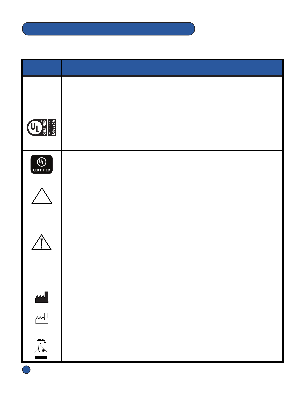
1.3 Labels and Descripons
UL Mark
ANSI/AAMI ES60601-1 AMD 1 (2012), "Medical
Electrical Equipment - Part 1:
General Requirements for Basic Safety and
Essenal Performance, Amendment 1.
CAN/CSA-C22.2 No. 60601-1 (2014), "Medical
Electrical Equipment - Part 1:
General Requirements for Basic Safety and
Essenal Performance
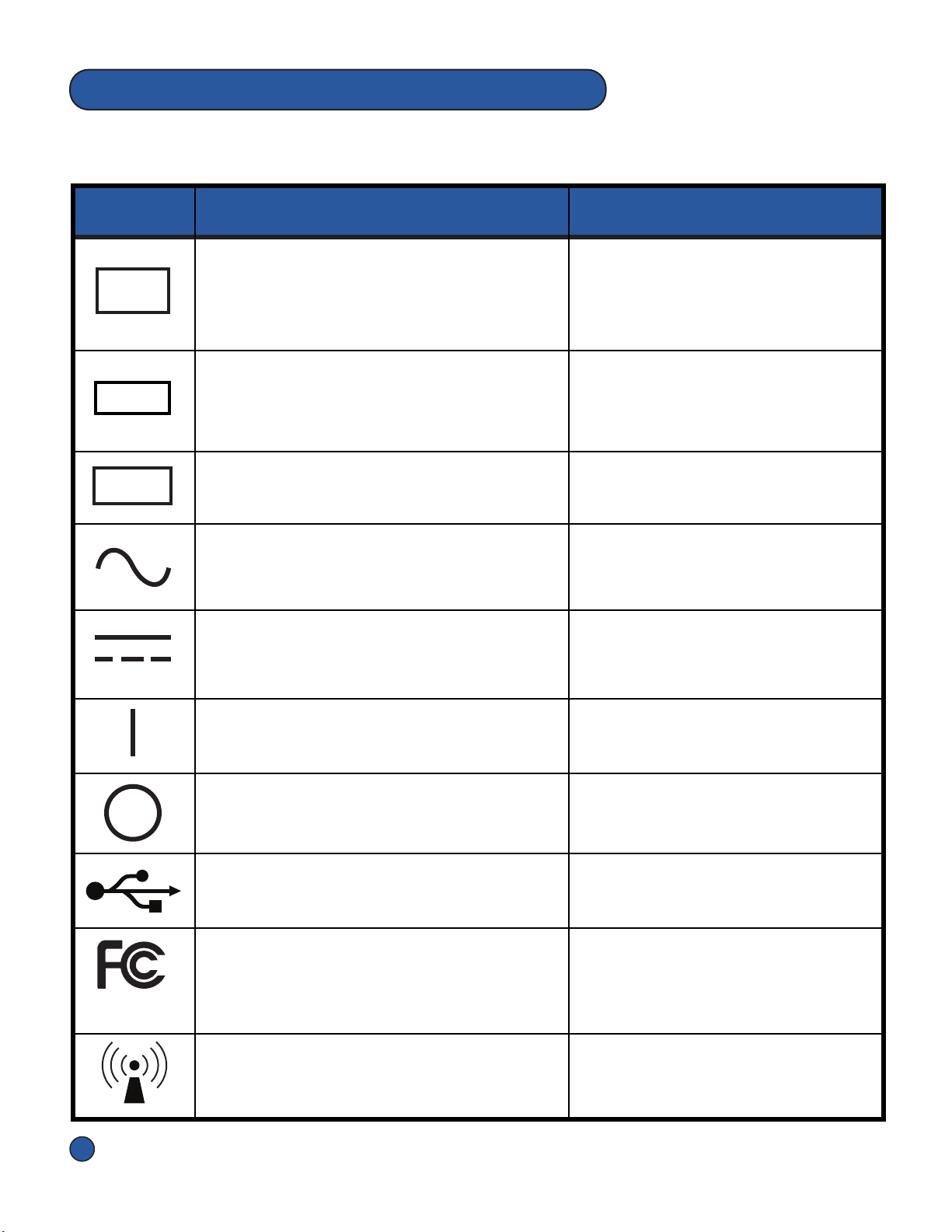
Label Descripon Applicaon
Pneumac Controller label
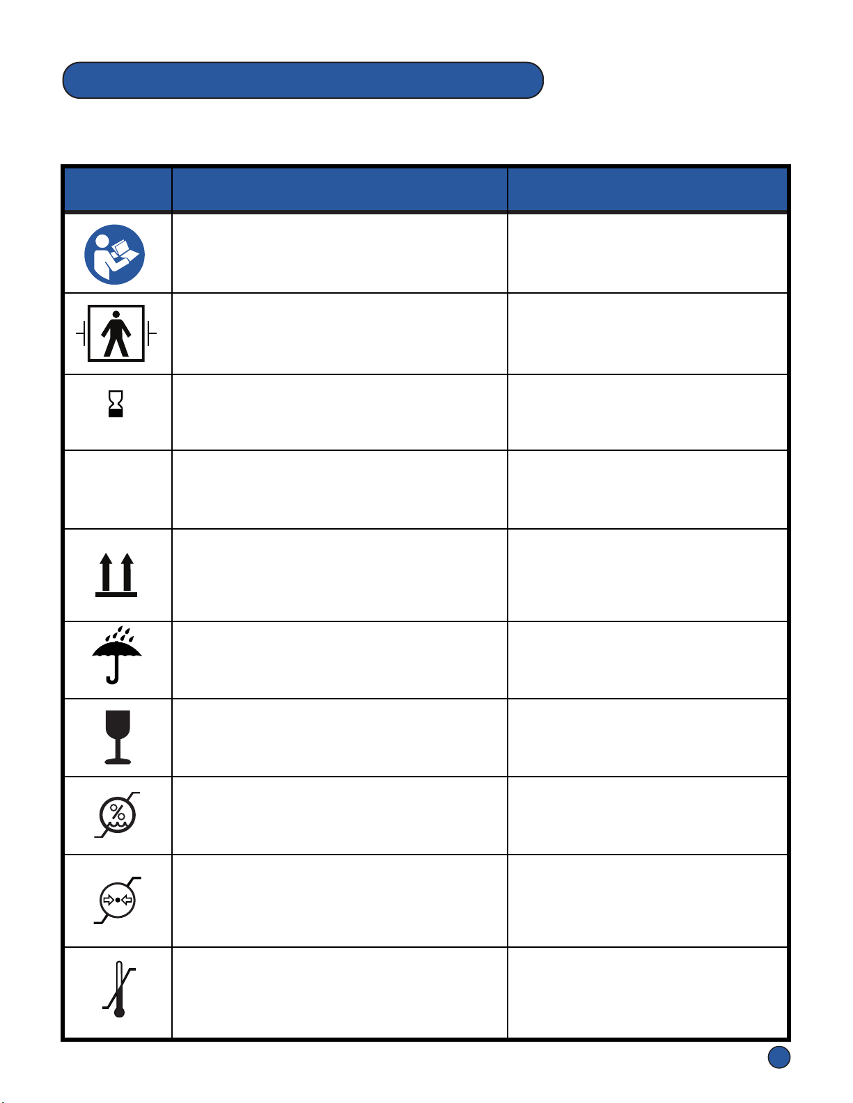
The Symbols below appear on the Pneumac Controller, Overlays, Hose Assembly,
Accessories and/or packaging.
NON
STERILE
Non-Sterile
Indicates a medical device that has not been
subjected to a sterilizaon process. Overlay labels & Overlay Box labels
Instrucons For Use
Cauon
Alerts the reader of a potenally hazardous
situaon which, if not avoided, may result in
minor or moderate injury to the user or
paent or damage to the product or other
property. This includes special care neces-
sary for the safe and effecve use of the
device and the care necessary to avoid
damage to the device that may occur as a
result of use or misuse.
Separate Collecon
Separate collecon for electronic waste
required.
Box labels, Overlay Box labels,
Overlay labels, Pneumac Controller
label, Hose Assembly label
Date of Manufacture
Indicates the date when the medical device
was manufactured.
Box labels, Pneumac Controller
label, Hose Assembly label,
Overlay labels
YYYY-MM-DD
Manufacturer
Indicates the medical device manufacturer.
Box labels & Pneumac
Controller label
UL Badge
Indicates UL compliance on markeng,
adversing, and packaging materials
Pneumac Controller label, Box
labels, Overlay labels, Hose
Assembly label
DOC# R01-0006-00004-AA
NOTE: Provides special informaon to make important instrucons clearer.