3
Planning the Drain
IMPORTANT:
A drain line hose is supplied with
the product. Should you require a
longer drain hose, it is important
that the installer utilize a hose
approved for detergents and high
temperature water.
The drain hose supplied with the dishwasher
meets an AHAM DW-1 test standard. You must
install an air gap in the drain if the drain hose is
connected to household plumbing lower than 20
inches (508mm) from the floor.
A disposal drain or waste tee must be a
minimum of 20 inches (508mm) from the
floor. The drain hose must be installed to an
inlet or waste tee above the drain trap in the
household plumbing. The drain hose supplied
with the dishwasher should be connected to a
minimum 1/2 inch I.D. drain connection. Longer
replacement drain hoses should be made from
detergent and heat resistant material and should
not exceed 12 feet in length.
Install the air gap in the sink or countertop
area adjacent to the dishwasher. Hook up a
section of drain hose (supplied by the installer)
from the air gap to the disposal. See disposal
manufacturer’s installation instructions for
correct drain hose mounting techniques.
Exercise caution; do not kink or pinch the drain
hose while installing the dishwasher in the
opening.
Wait for the Verifying Proper Operation section
to make the final drain line connection from the
dishwasher to the air gap.
Installing the Dishwasher
WARNING:
Excessive Weight Hazard
• Use two or more people
to move and install this
dishwasher
• Failure to do so can result in
back or other injury
Tip Over Hazard
• Do not use the dishwasher
until it has been completely
installed with anti-tip brackets
• Do not push down on the door
when open, doing so can result
in serious injury or cuts and
damage to the unit.
IMPORTANT:
Do not allow any material or the
electrical supply to be directly
behind the dishwasher when it
is pushed back into the opening.
Take care to feed the drain hose,
water supply line and electrical
cord into the adjacent cabinet
space without pinching these
items. Damaged water supply
or drain lines, due to poor
installation techniques, can cause
unnecessary water damage not
covered under warranty.
Begin the dishwasher installation with the
unit setting in front of the opening. To expose
the leveling legs the toe-kick plates must be
removed. To remove the toe-kick front plate,
manually slide it forward removing it from the
chassis. To remove the toe-kick rear plate, take
out the mounting screws. Feed the drain hose,
electrical cord, and water supply line through
the access hole in the side of the cabinet. Slide
the dishwasher back into the opening while
working the lines into the cabinet. Stop when the
dishwasher contacts the back wall or aligns with
the front cabinet opening.
WARNING:
1. Do not use a power driver to
adjust the rear leveling legs,
doing so may damage the
dishwasher.
2. Do not over torque the leveling
legs, this will cause distortion
in the dishwasher tank leading
to door alignment problems.
3. To prevent damaging the
dishwasher, adjust the
leveling legs only 1/2” (13mm)
per leg at a time.
Leveling the Dishwasher
To align the dishwasher correctly inside the
cabinet opening, the legs must be adjusted to
level the appliance. After centering the appliance
in the opening, leveling can be accomplished
by adjusting all four leveling legs. To verify front
to back level, remove the lower rack from the
dishwasher and place a level on the tank side
wall rack guides. To verify left to right level,
place a level on the tank lower front frame. To
adjust the front leveling legs, place a wrench on
the top of each leg and adjust where the top of
the dishwasher tank front trim is flush with the
lower edge of the countertop. To adjust the rear
leveling legs, rotate the #2 phillips drive shafts,
located at the toe-kick, to level the dishwasher
from front to back and left to right.
It is important to level the dishwasher from left
to right and front to back. Shimming may be
required on extremely uneven flooring materials.
If shims are needed, place the shim(s) under the
adjustable legs.
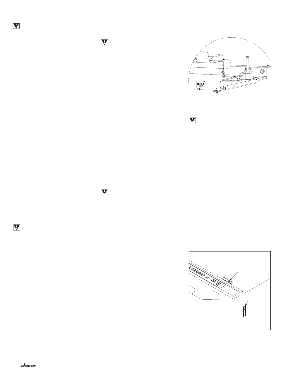
Leveling Adjustment Locations
IMPORTANT:
1. Make sure to anchor at least
one anti-tip bracket on each
side of the dishwasher.
2. The anchoring material must
be no more than 1/4” (6mm)
from the anti-tip bracket.
Securing Anti-Tip Brackets
To protect against possible tipping, caused by
heavy bottom rack loads on the door, be sure
to utilize the anti-tip brackets. There are anti-
tip mounting locations provided thought the
top of the dishwasher front frame and thought
the sides of the dishwasher front frame. For
recommended side anti-tip bracket anchoring,
insert the anchoring screw through the 1/2”
diameter tank access hole making sure that
the anchoring screw passes through the
anti-tip bracket located on the outside of the
dishwasher. For alternate top anti-tip bracket
anchoring, insert the anchoring screw through
the 1/2” diameter tank access hole making sure
that the anchoring screw passes through the
anti-tip bracket located on the outside of the
dishwasher.
Top anti-tip
bracket
Side anti-tip
bracket
Anti-Tip Bracket Locations
Front leg
adjustment
nut
Rear leg
adjustment
hex rod