- 2 -
K9 2400
K9 2440
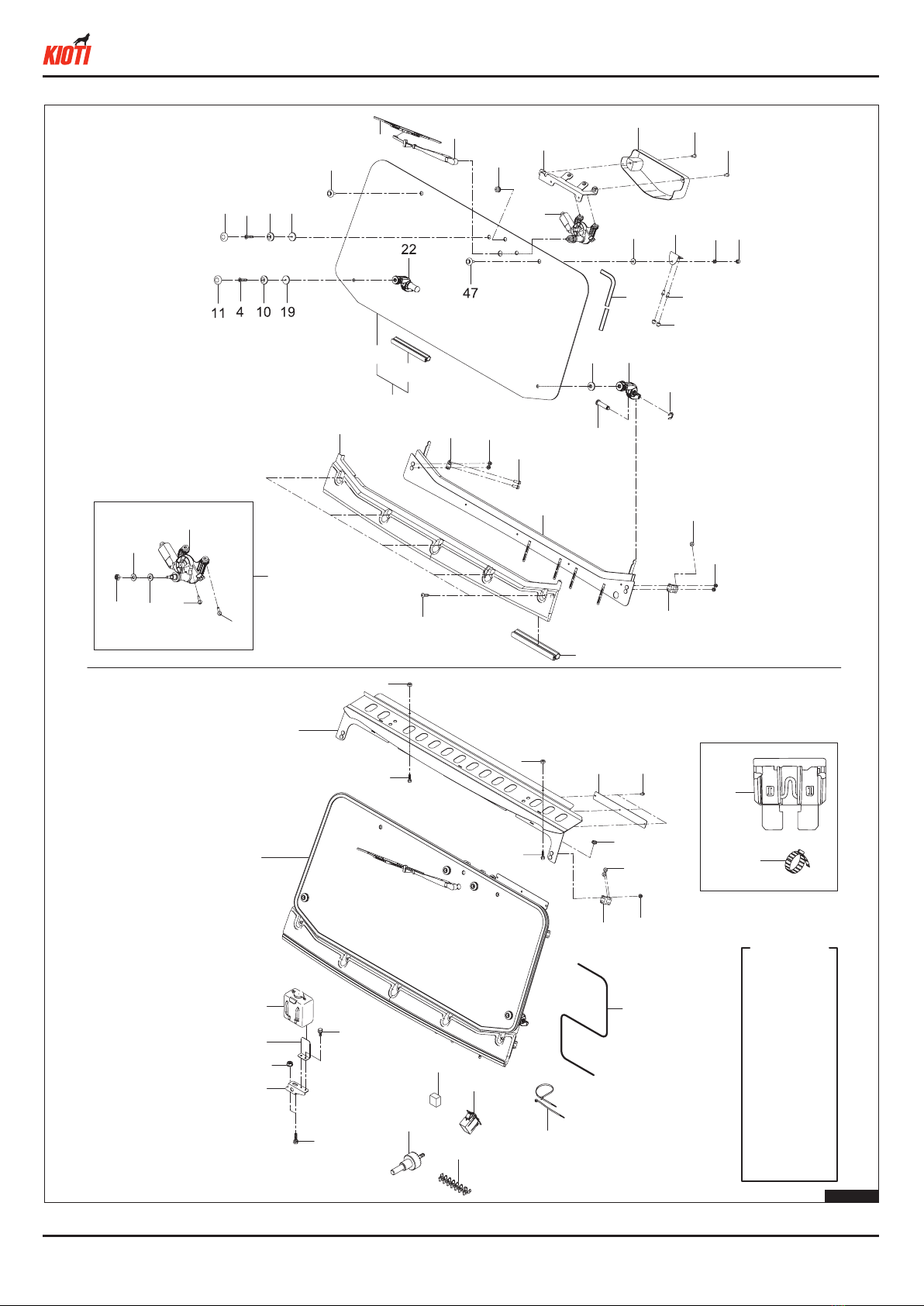
1. PACKING LIST & ACTUAL IMAGE
NO. Part No. Description Q'TY Remark
KIT 1 KIT 2 KIT 3 KIT 4 KIT 5
1 01123-50816 WITH_WASHER_BOLT 4 4 - - -
2 01123-50845 BOLT 2 2 - - -
3 02763-50080B FLANGE NUT 15 15 - - -
4 03016-50830 CROSS-RECESSED HEAD MACHINE SCREW 2 2 - - -
5 03016-50840 CROSS-RECESSED HEAD MACHINE SCREW 2 2 - - -
6 04613-50040 SNAP_RING 2 2 - - -
7 C7210-38511 SCREW 5 5 - - -
8 C7280-89211 SPHC 1 1 - - -
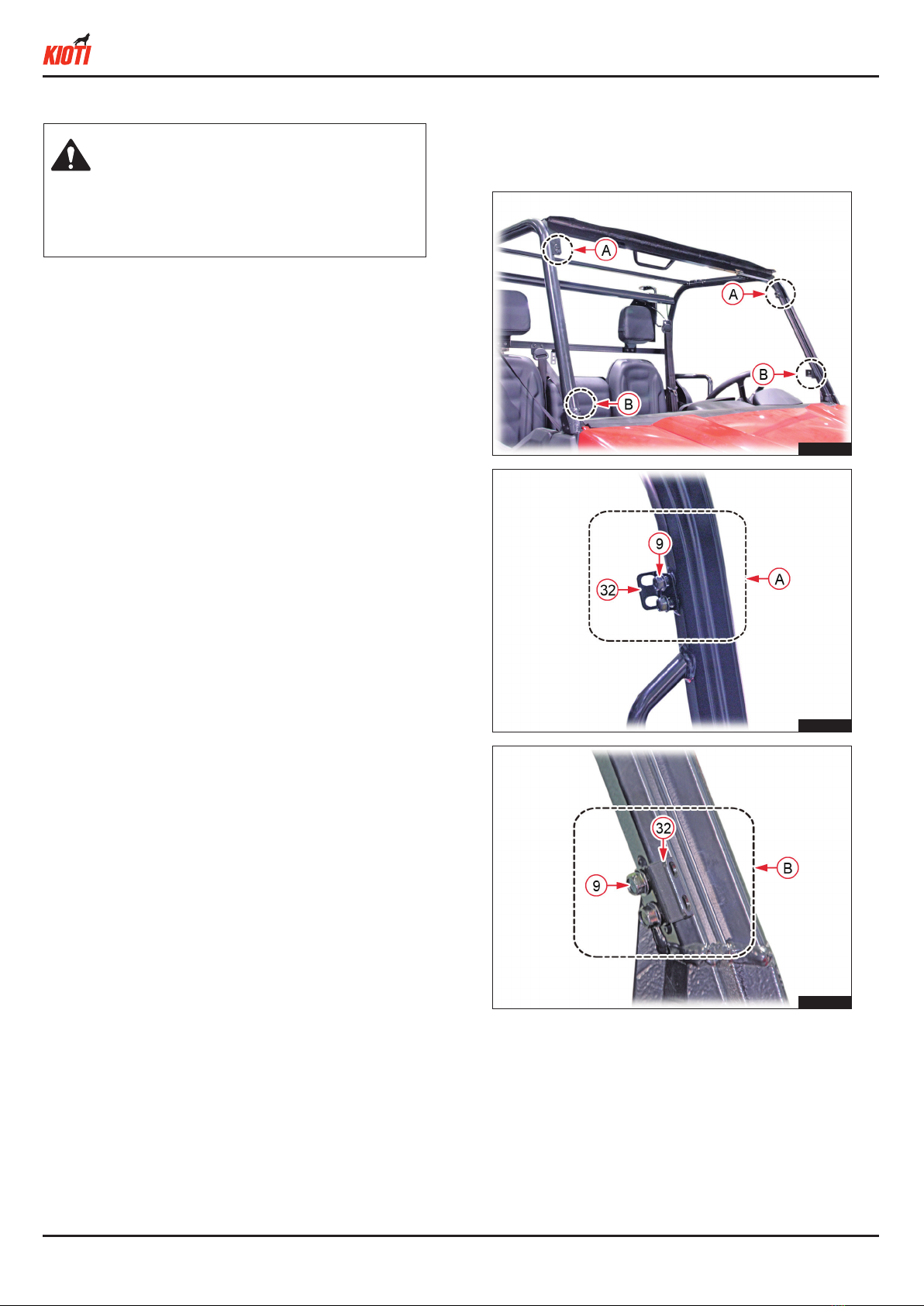
9 01754-50820B FLANGE BOLT 8 8 - - -
10 T4145-83711 COLLAR 4 4 - - -
11 T4145-83721 CAP,SEALING 4 4 - - -
12 T4340-87181 WHSHER LIQUID TANK ASSY 1 1 - - -
13 T4520-87402 PACKING, 1 2 2 - - -
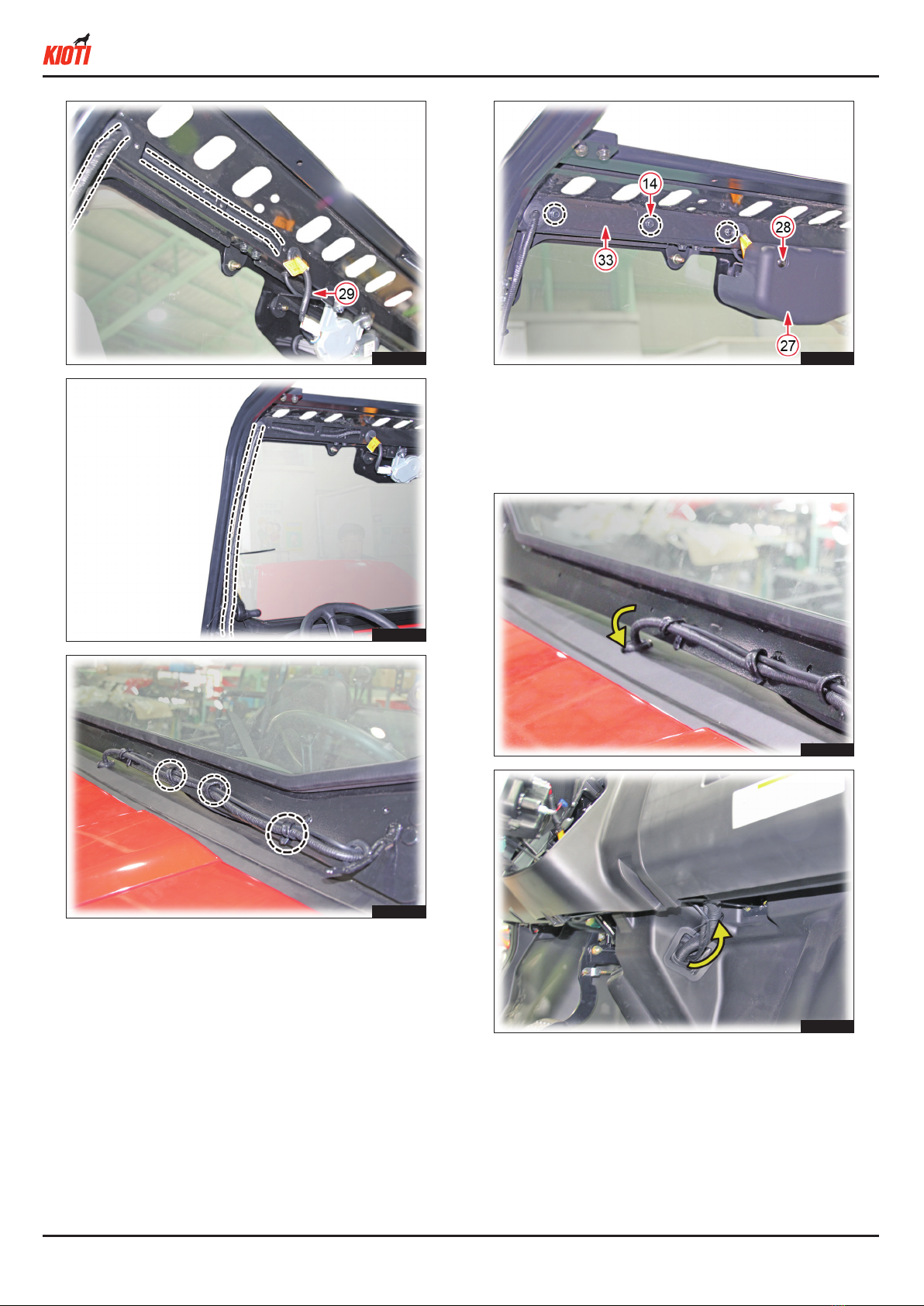
14 01754-50616B FLANGE BOLT 5 5 - - -
15 T4815-82431 WIPER, 16-INCH 1 1 - - -
16 T4815-89171 GROMET 1 1 - - -
17 T4815-93211 NUT 6 6 - - -
18 T4930-83701 HEAD PIN, SIDE MIRROR 2 2 - - -
19 T4930-83721 CUSHION, A 4 4 - - -
20 T4930-83731 CUSHION, B 4 4 - - -
21 T4930-85081 GRIP, SIDE, LH 1 1 - - -
22 T4930-85091 GRIP, SIDE, RH 1 1 - - -
23 T5270-69913 MOTOR, WIPER-FR 1 1 - - -
24 T5525-80331 JABARA 2 2 - - -
25 T5710-69971 RELAY 5P - - - 1 1
26 U3210-97221 BRACKET ASSY, FRONT WIPER MOTOR 1 1 - - -
27 U3210-97251 BRACKET, FRONT WIPER MOTOR 1 1 - - -
28 U3215-97161 CROSS-RECESSED HEAD MACHINE SCREW 2 2 - - -
29 UD26-0097A WIRE HARNESS, CONNECTING WIPER MOTOR - - 1 - -
UD26-0017C ASSY WIRE HARNESS, CONNECTING WIPER - - - 1 1
30 T4935-54232 SWITCH, WIPER, FR - - 1 1 -
UD26-0036A SWITCH, WIPER-FR LED - - - - 1
31 UD27-0022A GANISH CLIP 7 7 - - -
32 UD28-5966A UPR FRAME STAY 4 4 - - -
33 UD28-5968A ELEC COVER 1 1 - - -
34 UD28-5975A COVER LWR 1 1 - - -
35 UD28-5976A LWR COVER RUBBER 1 1 - - -
36 UD28-5977A WASHER HOSE 1 1 - - -
37 UD28-5982A SPRING HINGE 2 2 - - -
38 UD28-5986A TANK BRKT 1 1 - - -
39 UD28-5992A HOLE CUTTER 1 1 - - -
40 UD28-5993A ARM, WIPER 1 1 - - -
41 UD28-59BJC FRAME UPR ASS'Y 1 1 - - -
42 UD28-59BLB FRAME LWR ASS'Y 1 1 - - -
43 UD28-59CCA TEMPERED GLASS SUB ASS'Y 1 - - - -
UD28-59CDA LAMINATED GLASS SUB ASS'Y - 1 - - -
44 UD28-5981A FRT GLASS 1 1 - - -
45 UD28-5980A FRT TEMPERED GLASS 1----
UD28-5981A FRT GLASS - 1 - - -
46 T2198-82571 BAND, CABLE 3 3 - - -
47 T4620-81842 BOLT, CUSHION 2 2 - - -
48 UD28-59ACB TEMPERED GLASS 1 - - - -
UD28-59ADB LAMINATED GLASS - 1 - - -
49 TE15-0087A MOTOR, WIPER 1 1 - - -
50 TE15-0088A PACKING, WATERPROOF 1 1 - - -
51 TE15-0089A WASHER 1 1 - - -
52 TE15-0090A NUT 1 1 - - -
53 TE15-0091A BOLT 2 2 - - -
54 01754-50840B FLANGE BOLT 2 2 - - -
55 T5210-68682 FUSE 20A - - 1 - -
56 T2185-82551 BAND CORD - - - 4 4