Daewoo DLA-32H1 User manual

DAEWOO
MODELO:DLA-32H1
Chassis:MT5380
Product Type: Televisión de 32” LCD
Ver 1.0
Hisense Electric Co.,Ltd.
Apr. 2008

- 2 -
L
CD
T
V
Service Manual
Hisense Confidential
Contents
Contents.......................................................................................................................................................................- 2 -
Service Manual ...........................................................................................................................................................- 3 -
1. Precautions and notices.....................................................................................................................................- 3 -
1.1 Warning...................................................................................................................................................- 4 -
1.2 Notes.......................................................................................................................................................- 7 -
2. Product Function Specifications .....................................................................................................................- 10 -
2.1 Product Function...................................................................................................................................- 10 -
2.2 Specifications........................................................................................................................................- 13 -
3. LCD Panel Spec..............................................................................................................................................- 14 -
3.1 General Description ..............................................................................................................................- 14 -
3.2 General Features ...................................................................................................................................- 15 -
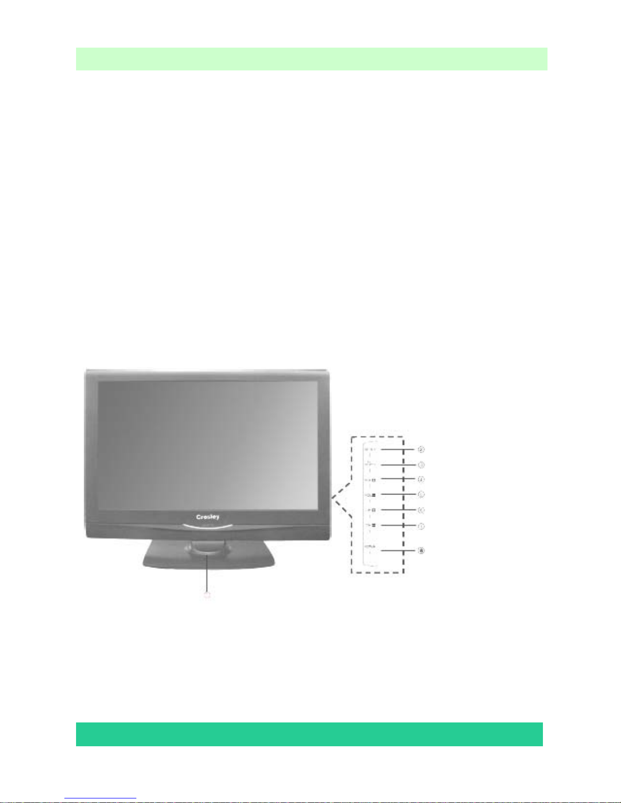
4. Chassis Layout and Overall Wiring Diagrams ...............................................................................................- 16 -
4.1 Boards and Chassis Layout...................................................................................................................- 16 -
4.2 Connectors ............................................................................................................................................- 17 -
4.3 Wires and Cables Overall Wiring Diagram(s)......................................................................................- 18 -
5. Factory/Service OSD Menu and Adjustment.......................................................¡Error! Marcador no definido.
5.1 To enter the Factory OSD Menu................................................................¡Error! Marcador no definido.
5.2 Factory OSD Menu....................................................................................¡Error! Marcador no definido.
5.3 Designer Menu(待小于数据) ....................................................................¡Error! Marcador no definido.
6. Software Upgrading........................................................................................................................................- 19 -
6.1 Get ready for upgrading........................................................................................................................- 23 -
6.2 Upgrading with the MtkTool .....................................................................¡Error! Marcador no definido.
7. Troubleshooting ..............................................................................................................................................- 26 -
7.1 Troubleshooting for Remote Control....................................................................................................- 30 -
7.2 Troubleshooting for Function Key........................................................................................................- 31 -
7.3 TV won’t Power On..............................................................................................................................- 32 -
7.4 Troubleshooting for Audio....................................................................................................................- 33 -
7.5 Troubleshooting for TV/VGA/HDMI input..........................................................................................- 34 -
7.6 Troubleshooting for YPbPr input..........................................................................................................- 35 -
7.7 Troubleshooting for Video/S-Video input.............................................................................................- 36 -
8. Schematic circuit diagram ...................................................................................¡Error! Marcador no definido.

- 3 -
L
CD
T
V
Service Manual
Hisense Confidential
Service Manual
1. Precautions and notices
BEFORE SERVICING THE LCD TV, READ THE SAFETY PRECAUTIONS IN
THIS MANUAL.
WHEN REPLACEMENT PARTS ARE REQUIRED, BE SURE TO USE
REPLACEMENT PARTS SPECIFIED BY THE MANUFACTURER.
Proper service and repair is important to the safe, reliable operation of all Hisense
Electric Co., Ltd Equipment. The service procedures recommended by Hisense and
described in this Service Guide are effective methods of performing service operations.
Some of these service operations require the use of tools specially designed for the
purpose. The special tools should be used when and as recommended.
It is important to note that this manual contains various CAUTIONS and NOTICES
which should be carefully read in order to minimize the risk of personal injury to service
personnel. The possibility exists that improper service methods may damage the
equipment. It is also important to understand that these CAUTIONS and NOTICES ARE
NOT EXHAUSTIVE. Hisense could not possibly know, evaluate and advise the service

- 4 -
L
CD
T
V
Service Manual
Hisense Confidential
trade of all conceivable ways in which service might be done or of the possible
hazardous consequences of each way. Consequently, Hisense has not undertaken any
such broad evaluation. Accordingly, a serviceman that uses a service procedure or tools,
which are not recommended by Hisense, must first satisfy himself thoroughly that
neither his safety nor the safe of the equipment will be jeopardized by the service
method selected.
Hereafter throughout this manual, Hisense Electric Co., Ltd will be referred to as
Hisense.
1.1 Warning
1.1.1
Critical components having special safety characteristics are identified with a by the
Ref. No. in the parts list. Use of substitute replacement parts, which do not have the
same specified safety characteristics, may create shock, fire, or other hazards.
Under no circumstances should the original design be modified or altered without
written permission from Hisense. Hisense assumes no liability, express or implied,
arising out of any unauthorized modification of design. Serviceman assumes all liability.
DANGERCAUTION CAUTION
TO ENSURE THE CONTINUED RELIABILITY OF THIS PRODUCT, USE ONLY
ORIGINAL MANUFACTURER'S REPLACEMENT PARTS, WHICH ARE LISTED WITH
THEIR PART NUMBERS IN THE PARTS LIST SECTION OF THIS SERVICE GUIDE.

- 5 -
L
CD
T
V
Service Manual
Hisense Confidential
1.1.2.
All ICs and many other semiconductors are susceptible to electrostatic discharges (ESD).
Careless handling during repair can reduce life drastically. When repairing, make sure
that you are connected with the same potential as the mass of the set by a wristband with
resistance. Keep components and tools also at this same potential.
1. Never replace modules or other components while the unit is switched on.
2. When making settings, use plastic rather than metal tools. This will prevent any
short circuits and the danger of a circuit becoming unstable.
1.1.3
To prevent electrical shock, do not use this polarized ac plug with an extension cord,
receptacle, or the outlet unless the blades can be fully inserted to prevent blade exposure.
To prevent electrical shock, match wide blade or plug to wide slot, fully insert.
1.1.4
When replacement parts are required, be sure to use replacement parts specified by the
manufacturer or have the same characteristics as the original part. Unauthorized
substitutions may result in fire, electric shock, or other hazards.
1.1.5
Safety regulations require that after a repair the set must be returned in its original
condition. In particular attention should be paid to the following points.
-Note: The wire trees should be routed correctly and fixed with the mounted cable

- 6 -
L
CD
T
V
Service Manual
Hisense Confidential
clamps.
-The insulation of the mains lead should be checked for external damage.
1.1.6
(1) Do not touch Signal and Power Connector while this product operates. Do not
touch EMI ground part and Heat Sink of Film Filter.
(2) Do not supply a voltage higher than that specified to this product. This may damage
the product and may cause a fire.
(3) Do not use this product in locations where the humidity is extremely high, where it
may be splashed with water, or where flammable materials surround it. Do not install
or use the product in a location that does no satisfy the specified environmental
conditions. This may damage the product and may cause a fire.
(4) If a foreign substance (such as water, metal, or liquid) gets inside the panel module,
immediately turn off the power. Continuing to use the product may cause fire or
electric shock.
(5) If the product emits smoke, and abnormal smell, or makes an abnormal sound,
immediately turn off the power. Continuing to use the product, it may cause fire or
electric shock.
(6) Do not disconnect or connect the connector while power to the product is on. It
takes some time for the voltage to drop to a sufficiently low level after the power has
been turned off. Confirm that the voltage has dropped to a safe level before
disconnecting or connecting the connector.

- 7 -
L
CD
T
V
Service Manual
Hisense Confidential
(7) Do not pull out or insert the power cable from/to an outlet with wet hands. It may
cause electric shock.
(8) Do not damage or modify the power cable. It may cause fire or electric shock.
(9) If the power cable is damaged, or if the connector is loose, do not use the product:
otherwise, this can lead to fire or electric shock.
(10) If the power connector or the connector of the power cable becomes dirty or dusty,
wipe it with a dry cloth. Otherwise, this can lead to fire.
(11) Use only with the cart, stand, tripod, bracket, or table specified by the
manufacturer, or sold with the apparatus. When a cart is used, use caution when
moving the cart/apparatus combination to avoid injury from tip-over.
1.2 Notes
Notes on Safe Handling of the LCD panel and during service
The work procedures shown with the Note indication are important for ensuring the
safety of the product and the servicing work. Be sure to follow these instructions.
• Before starting the work, secure a sufficient working space.
• At all times other than when adjusting and checking the product, be sure to turn OFF
the POWER Button and disconnect the power cable from the power source of the TV
during servicing.
• To prevent electric shock and breakage of PC board, start the servicing work at least 30

- 8 -
L
CD
T
V
Service Manual
Hisense Confidential
seconds after the main power has been turned off. Especially when installing and
removing the power board, start servicing at least 2 minutes after the main power has
been turned off.
• While the main power is on, do not touch any parts or circuits other than the ones
specified. If any connection other than the one specified is made between the measuring
equipment and the high voltage power supply block, it can result in electric shock or
activation of the leakage-detection circuit breaker.
• When installing the LCD module in, and removing it from the packing carton, be sure
to have at least two persons perform the work.
• When the surface of the panel comes into contact with the cushioning materials, be
sure to confirm that there is no foreign matter on top of the cushioning materials before
the surface of the panel comes into contact with the cushioning materials. Failure to
observe this precaution may result in, the surface of the panel being scratched by foreign
matter.
• When handling the circuit board, be sure to remove static electricity from your body
before handling the circuit board.
• Be sure to handle the circuit board by holding the large parts as the heat sink or
transformer. Failure to observe this precaution may result in the occurrence of an
abnormality in the soldered areas.
• Do not stack the circuit boards. Failure to observe this precaution may result in
problems resulting from scratches on the parts, the deformation of parts, and

- 9 -
L
CD
T
V
Service Manual
Hisense Confidential
short-circuits due to residual electric charge.
• Routing of the wires and fixing them in position must be done in accordance with the
original routing and fixing configuration when servicing is completed. All the wires are
routed far away from the areas that become hot (such as the heat sink). These wires are
fixed in position with the wire clamps so that the wires do not move, thereby ensuring
that they are not damaged and their materials do not deteriorate over long periods of time.
Therefore, route the cables and fix the cables to the original position and states using the
wire clamps.
• Perform a safety check when servicing is completed. Verify that the peripherals of the
serviced points have not undergone any deterioration during servicing. Also verify that
the screws, parts and cables removed for servicing purposes have all been returned to
their proper locations in accordance with the original setup.
The lightning flash with arrowhead symbol, within an equilateral
triangle is intended to alert the user to the presence of uninsulated
dangerous voltage within the products enclosure that may be of sufficient magnitude to
constitute a risk of electric shock.
The exclamation point within an equilateral triangle is intended to alert
the user to the presence of important operating and maintenance (servicing)
instructions in the literature accompanying the set.

- 10 -
L
CD
T
V
Service Manual
Hisense Confidential
2. Product Function Specifications
2.1 Product Function
Front Cabinet
Back Cabinet

- 11 -
L
CD
T
V
Service Manual
Hisense Confidential

- 12 -
L
CD
T
V
Service Manual
Hisense Confidential

- 13 -
L
CD
T
V
Service Manual
Hisense Confidential
2.2 Specifications

- 14 -
L
CD
T
V
Service Manual
Hisense Confidential
NOTE: Specifications and design are subject to possible modifications without notice due
to improvements。
3. LCD Panel Spec
3.1 General Description
AX080D002F is a 31.5” TFT Liquid Crystal Display module with 16-EEFL
Backlight unit and a single LVDS interface.
This module supports 1366 x 768 WXGA format and can display 16.7M colors
(8-bits colors).

- 15 -
L
CD
T
V
Service Manual
Hisense Confidential
3.2 General Features

- 16 -
L
CD
T
V
Service Manual
Hisense Confidential
4. Chassis Layout and Overall Wiring Diagrams
4.1 Boards and Chassis Layout
No Description Part No Type/Model PCB/ Model
TV(1) Main BD 116468 RSAG2.908.1230-4 RSAG7.820.1276
TV(2) In/Out connector
board 116434 RSAG2.908.1291 5RSAG7.820.1263
TV(3) LED / IR Board 114175 RSAG2.908.1169 40RSAG7.820.1213
TV(4) Key Board 114174 RSAG2.908.1168 20RSAG7.820.1214
TV(5) Power Board 114922 RSAG2.908.916-27\ROH E/RSAG7.820.848A
TV(1)
TV(2)
TV(5)
TV(3)
TV(4)

- 17 -
L
CD
T
V
Service Manual
Hisense Confidential
4.2 Connectors
Main Board
Location No. Specification Description
J901 Jack/FF-HX19-10\ROH LVDS signal between MB and panel
J101 Jack/TJC10-14A\ROH Power from Power BD
J1411 Jack/TJC10-3A\ROH Buttons (connect key BD and main BD)
J1410 Jack/TJC10-5A\ROH IR, LED
J703 Jack/TJC10-4A\ROH Serial Port connector
J902 Jack/TJC3-4A\ROH Video/Audio signal
J1201 Jack/A2006WSO-2×13P\ROH Headphone Audio Signal
J801 Jack/TJC3-4A\ROH Audio signal to speakers
J901 J101
J1411 J1410
J902
J703
J801
J1201

- 18 -
L
CD
T
V
Service Manual
Hisense Confidential
4.3 Wires and Cables Overall Wiring Diagram(s)
No DESCRIPTION SPECIPICATION NOTE
1 LVDS signal Connector/HX-0147\ROH Main BD J901<-->Panel
2 +5V, +12V supply to Main BD Connector /TJC10T-14Y-200\ROH Main BD J101<-->Power BD XP812
3 Main Power Connector /TJC2-3Y-300-2\ROH Power Inlet-->Power BD XP801
4 Buttons Connector /TJC10T-3Y-800\ROH Main BD J1411<--> Key BD XPK01
5 LED & IR Connector /TJC10T-5Y-500\ROH Main BD J1410<-->IR &LED BD XPR01
6 Audio out put (R/L) Connector /TJC3H-4Y-650-900\ROH Main BD J801<-->Speakers
7 Headphone Audio Connector /TJC3T-4Y-300\ROH Main BD J902<-->I/O CON BD XP02
8 Serial data Connector /TJC10T-4Y-350\ROH Main BD J703<-->I/O CON BD XP03
9 Video/Audio signal Connector /HX-2026C400\ROH Main BD J1201<-->I/O CON BD XP01
10-1 Backlight Power Connector /HX-3005B450\ROH Power BD XP810<--> Panel left backlight port
10-2 Backlight Power Connector /HX-3005B350\ROH Power BD XP809<--> Panel right backlight port

- 19 -
L
CD
T
V
Service Manual
Hisense Confidential
5. Factory/Service OSD Menu and Adjustment
5.1 To enter the Factory OSD Menu
a. With factory RC (remote control)
1. Press “M” button and enter factory mode.
2. Press “Menu” button and enter factory OSD menu.
3. Press “CH+”/“CH-” button select the function menu, press “VOL+”/“VOL-” enter the selected
function menu. Press “VOL+”/“VOL-” button adjust values in the menu.
b. With user’s RC
1. Power TV On
2. Press Menu button and call up User OSD Menu
3. Select Audio-> Balance
4. Enter 0->5->3 ->2 in sequence.
Note: If necessary, re-do number keys.
5. Factory OSD appears.
6. Press Menu again and leave factory OSD.
5.2 Factory OSD Menu
5.2.1 White Balance
Note: Different source has different WB values. Before adjusting, please change to desired source.
1. Auto Color
For VGA and Component Video sources, WB values must be adjusted.
Before adjusting, please change to desired source and right timing and pattern.
source Timing Pattern Notes
1 ADC VGA 1024*768 gray-3color For VGA source
2 ADC HDTV 720P gray-3color For Component Video
a. Select the item “Auto Color”.
b. Press VOL+ button to auto color.

- 20 -
L
CD
T
V
Service Manual
Hisense Confidential
c. Close the OSD menu after 5 seconds.
5.2.2 Factory Option
Item Default Options Notes
1 MODE M M, U
M-Can enter factory mode
with factory RC or user RC.
U-Can enter factory mode only
with user’s RC.
Note: MODE “M” is only used for factory production.
5.2.3 Version Info
Item Default Options Note
1 Version LHD32W19NUS_E002
Software version
2 Date r.1.02_0308
The date of current version
Note: Software version info of the TV, readable only.
5.2.4 Clear the EEPROM
Item Meaning Note
1 Clear partly
Clean data except
WB data and Auto Color data
2 Clear completely Clean all data
Note: The factory menu date varies according to different sources. Incase changing the factory
data by error, you can choose to “clear the EEPROM”, by which you can resume the default
value.
To clear the EEPROM:
Table of contents
Other Daewoo LCD TV manuals

Daewoo
Daewoo DLP-20J1 User manual

Daewoo
Daewoo LA37L1B1LM User manual

Daewoo
Daewoo DLA-32C7LAB User manual

Daewoo
Daewoo LV32L1B1LM User manual

Daewoo
Daewoo DLT-19L1T Instruction Manual

Daewoo
Daewoo DLP-20J1 User manual

Daewoo
Daewoo DSL15M1TC User manual

Daewoo
Daewoo DSL-15D3 User manual

Daewoo
Daewoo DLT-32C2 User manual

Daewoo
Daewoo DLP-26C2 User manual

Daewoo
Daewoo DLM-32C3 Series User manual

Daewoo
Daewoo DLP-17D3 User manual

Daewoo
Daewoo DLP-26C2 User manual

Daewoo
Daewoo DLP-3212L User manual

Daewoo
Daewoo DLT-20W2 User manual

Daewoo
Daewoo DLM-42U1 User manual

Daewoo
Daewoo DLP-26C3SMB User manual

Daewoo
Daewoo DLP-26C2F Series User manual

Daewoo
Daewoo DLN-15D3AHS User manual

Daewoo
Daewoo DLX-32C7 User manual