Daewoo KBE-6R2SSS User manual

Service Manual
Electric Oven
Model: KBE-6R2SSS
KBE-6R2SMO
S/M No. :
June 2014
Caution
:
In this Manual, some parts can be changed for improving,
their performance without notice in the parts list. So, if you
need the latest parts information, please refer to PPL(Parts
Price List) in Service Information Center (http://svc.dwe.co.kr).
Dongbu Daewoo Electronics
KBE-6R2SSS_6R2SMO(SM)_프랑스향.indd 1 2014-07-18 오후 4:34:21

11
TABLE OF CONTENTS
1. SAFETY AND PRECAUTIONS ...................................................................................................................................... 2
2. SPECIFICATIONS .......................................................................................................................................................... 3
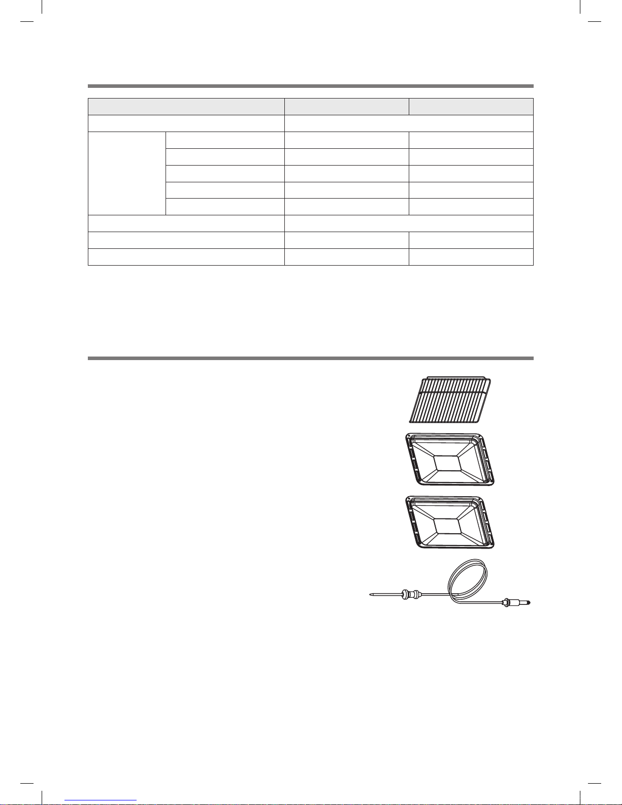
3. ACCESSORIES .............................................................................................................................................................. 3
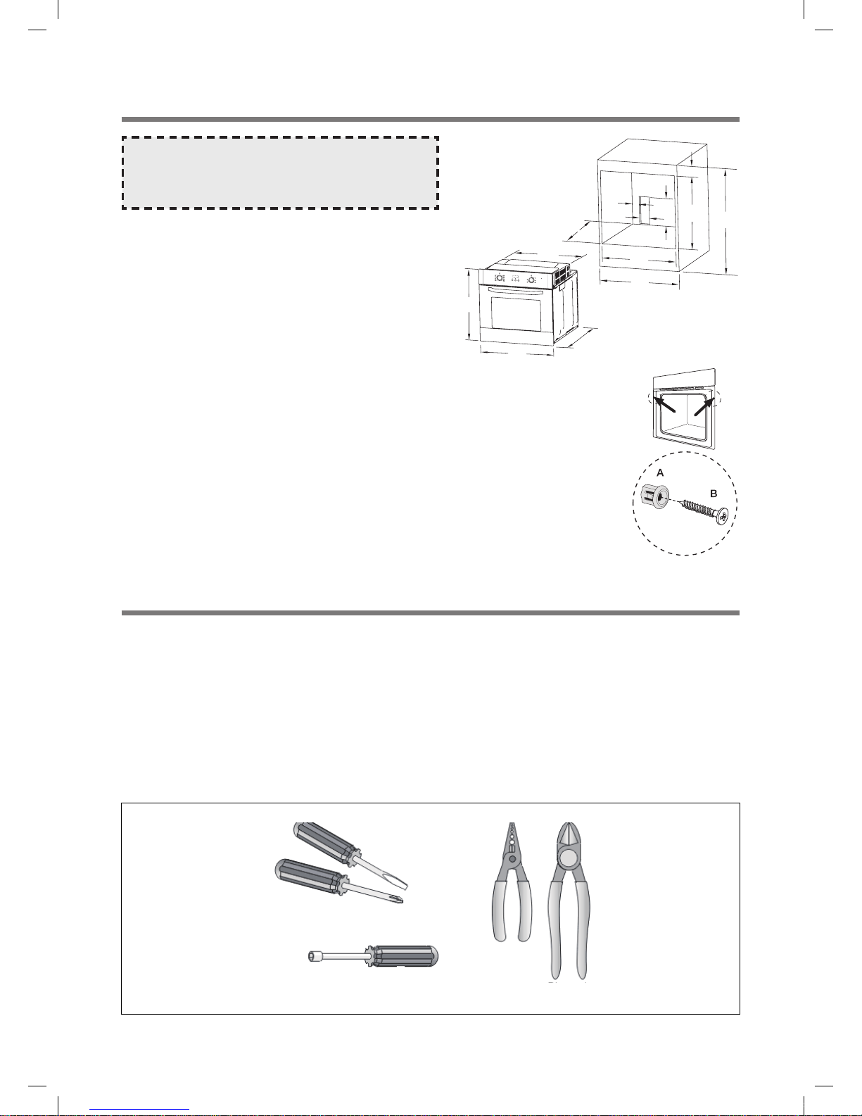
4. INSTALLATION .............................................................................................................................................................. 5
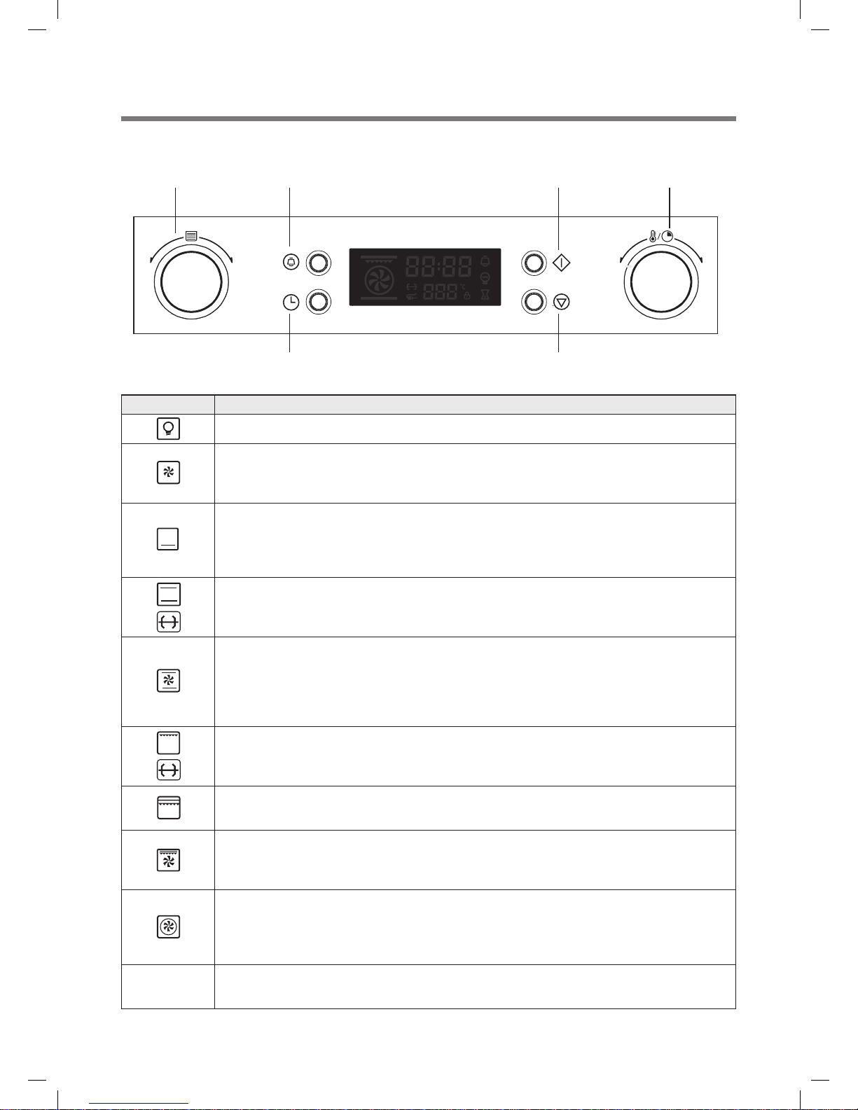
5. CONTROL PANEL.......................................................................................................................................................... 6
6. DISASSEmbLY AND ASSEmbLY................................................................................................................................. 8
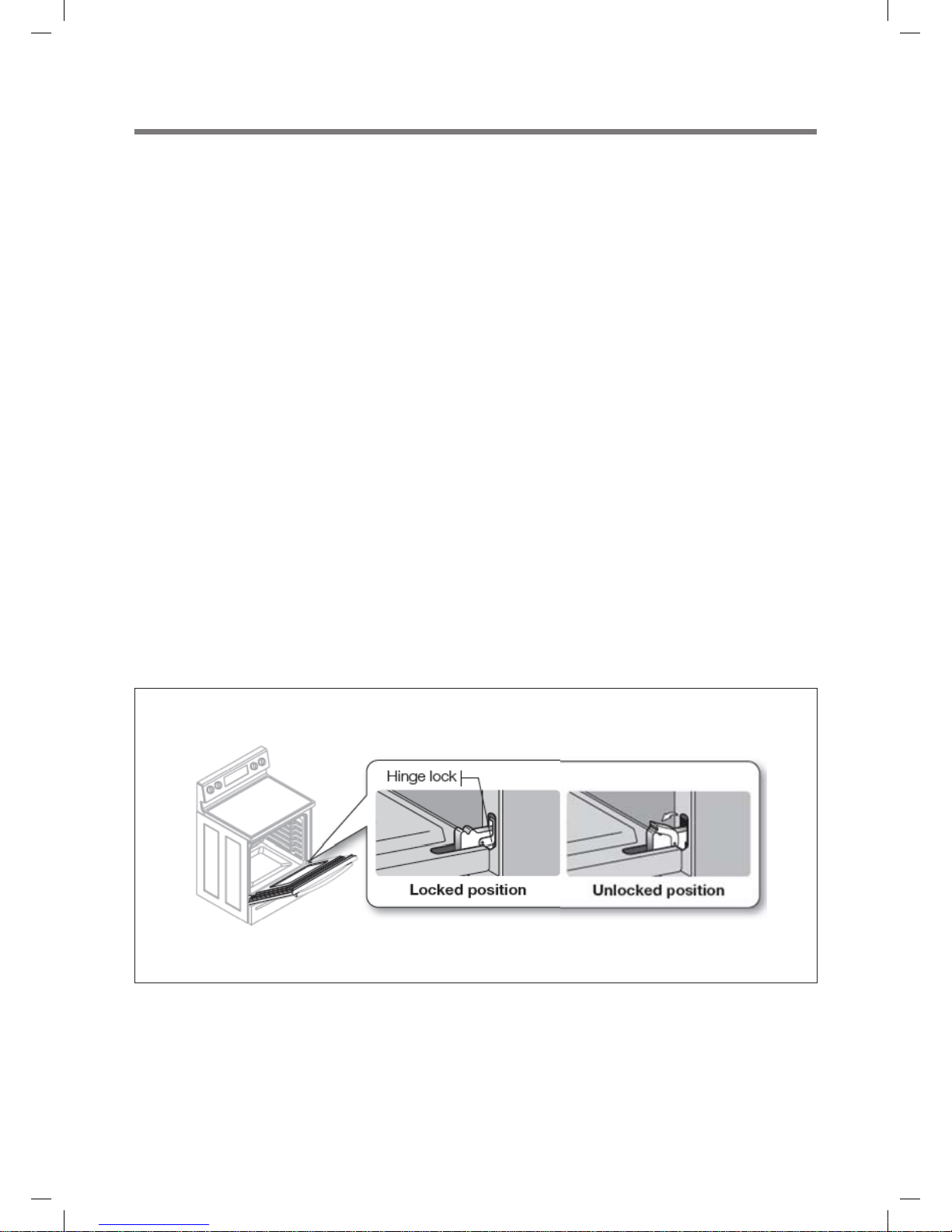
DOOR REMOVAL.......................................................................................................................................................... 8
DOOR INSTALLATION.................................................................................................................................................. 8
REMOVING THE OVEN FROM THE WALL ................................................................................................................. 9
DOOR COMPONENTS ................................................................................................................................................. 9
FRONT DOOR GLASS ASSEMBLY ........................................................................................................................... 10
CONTROL PANEL....................................................................................................................................................... 11
CONTROL PANEL REMOVAL .................................................................................................................................... 11
OVEN CONTROLLER REMOVAL............................................................................................................................... 11
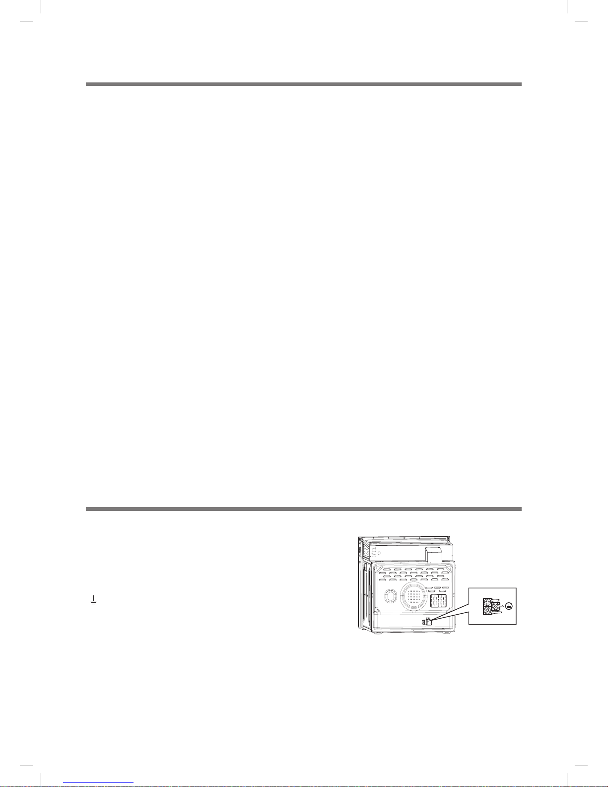
COMPONENTS BEHIND THE BACK COVER............................................................................................................ 12
REMOVING THE BACK COVER................................................................................................................................. 12
CONVECTION ELEMENT AND FAN .......................................................................................................................... 12
CONVECTION BAFFLE REMOVAL............................................................................................................................ 12
CONVECTION ELEMENT DISASSEMBLY................................................................................................................. 13
CONVECTION FAN REMOVAL .................................................................................................................................. 13
CONVECTION BAFFLE INSTALLATION.................................................................................................................... 13
BAKE ELEMENT ASSEMBLY REMOVAL .................................................................................................................. 14
BROIL ELEMENT ASSEMBLY REMOVAL ................................................................................................................. 15
TEMPERATURE SENSOR REMOVAL ....................................................................................................................... 16
COOLING FAN (BLOWER) ........................................................................................................................................... 1
7. ELECTRICAL WIRINg ................................................................................................................................................. 18
8. TROUbLEShOOTS ...................................................................................................................................................... 22
9. ERROR CODES............................................................................................................................................................ 23
KBE-6R2SSS_6R2SMO(SM)_프랑스향.indd 1 2014-07-18 오후 4:34:21

2
1. SAFETY AND PRECAUTIONS
ImPORTANT SAFETY INSTRUCTIONS
Read and follow all instructions before using your oven to prevent the risk of re, electric shock, personal injury, or damage
when using the range. This guide does not cover all possible conditions that may occur. For further assistance contact your
service agent or manufacturer.
• You should use two or more people to move and install range.
• You never pull or push any handles of door to move and install range.
• Power supply cord and plug should not be modied. If it will not t the outlet, have a proper outlet Installed by a
qualified electrician.
• Electrical ground is required on this appliance.
• You should make sure that the power cord is not pinched by the range or heavy objects.
- Failure to do so can result in serious burns or electrical shock.
• You should put on gloves during the installation or service procedure.
ImPORTANT
NOTE : This oven is designed for Built-in use only.
The wire in this mains lead coloured in accordance with the following code.
Green-and-yellow : Earth
Blue : Neutral
Brown : Live
As the colours of the wires in the mains lead of this appliance may not correspond with the
coloured markings identifying the terminals in your plug, proceed as follows.
The wire which is coloured green-and-yellow must be connected to the terminal in the plug
which is marked with the letter ‘E’ or by earth symbol or green-and-yellow.
The wire which is coloured blue must be connected to the terminal which is marked with the
letter ‘N’ or coloured black.
The wire which is coloured brown must be connected to the terminal which is marked with
the letter ‘L’ or coloured red.
KBE-6R2SSS_6R2SMO(SM)_프랑스향.indd 2 2014-07-18 오후 4:34:21

3
2. SPECIFICATIONS
3. ACCESSORIES
MODEL KBE-6R2SSS KBE-6R2SMO
POWER SUPPLY 230V~, 50 Hz
POWER
CONSUMPTION
Top Heater 1,000 W 1,000 W
Bottom Heater 1,000 W 1,000 W
Convection Heater 2,000 W 2,000 W
GRILL Heater 2,000 W 2,000 W
MAX. 3,200 W 3,000 W
OUTSIDE DIMENSION (W x H x D) 595 x 595 x 575
NET WEIGHT 39 kg 33 kg
CAVITY VOLUME 65 ℓ65 ℓ
Bake rack : For grilling and roasting meals. You could use it with cake
pan and other baking pots.
Bake tray : The baking tray could be used for the preparation of cakes,
cookies and other pastries.
Dripping tray : The dripping tray is good for roasting to prevent liquids
from dropping onto the bottom of the oven.
Meat probe (Optional) : Before using, insert the probe into the center of
the thickest portion of meat or into the inner thigh or breast of poultry,
away from fat or bone. Place food in oven and connect the meat probe.
Keep probe as far away from heat source as possible. Close oven door.
KBE-6R2SSS_6R2SMO(SM)_프랑스향.indd 3 2014-07-18 오후 4:34:21

4
SECURINg ThE OvEN TO ThE CABINET
TOOLS
Most of the tools that you might need are shown below. Some are optional. The reason for the option is explained.
ELECTRICAL PLIERS or STRIPPERS and Door Removal : For cutting and stripping small electrical wire.
VOM (VOLT-OHM METER): For testing electrical circuits. If you do not have one, please get one. An inexpensive one will
suffice, as long as it has both "AC Voltage" and "Resistance" (i.e. Rx1, Rx10) settings on the dial. It will do for our purposes.
BUTT CONNECTORS, CRIMPERS, WIRE NUTS and ELECTRICAL TAPE: For splicing small wire. When splicing wire on
ovens, you must make sure you use high-temp connections, such as porcelain wire nuts, high-temp terminals and fiber-
glass insulated wire.
ALLIgATOR JUmPERS (sometimes called a "CHEATER" or "CHEATER WIRE"): Available at your local electronics store.
SCREW-DRIVERS: Both flat and Phillips head; two or three sizes of each. It's best to have at least a stubby, 4- and 6-inch
sizes.
NUT-DRIVERS, WRENCHS: You will need a 1/4 to 1/2 inch size.
Screwdrivers:
Flat
Phillips
Nutdrivers:
Electrician's
Diagonals
Pliers
575
595
595
560
600 850
50
80
250
100
570
600
560
NOTE : The number of a accessories included depends
on the particular appliance purchased.
1. Fit oven into the cabinet recess.
2. Open the oven door.
3. Secure the oven to the kitchen cabinet with two distance holders "A" which fit the holes in the
oven frame and fit the two wood screws "B".
KBE-6R2SSS_6R2SMO(SM)_프랑스향.indd 4 2014-07-18 오후 4:34:21

5
1. Steady, flat location
This oven should be set on a steady, flat surface.
This oven is designed for Built-in use only.
2. Leave space behind and side
All air vents should be kept a clearance. If all vents are covered during operation, the oven may overheat and, eventually,
cause failure.
3. Away from radio, and TV sets
Poor television reception and radio interference may result if the oven is located close to a TV, Radio, antenna or feeder
and so on.
Position the oven as far from them as possible.
4. Away from heating appliances and water taps
Keep the oven away from hot air, steam and splash when choosing a place to position it, or the insulation might be
adversely affected and breakdowns occur.
5. Power supply
•Checkyourlocalpowersource.
This oven requires 230V, 50Hz.
•Thevoltageusedmustbethesameasspecifiedonthisoven.Usingahighervoltagemayresultinafireorother
accident causing oven damage. Using low voltage will cause slow cooking. We are not responsible for damage
resulting from use of this oven with a voltage of ampere fuse other than those specified.
•Thisapplianceissuppliedwithcableofspecialtype,which,ifdamaged,mustberepairedwithcableofsametype.
Such a cable can be purchased from DAEWOO and must be installed by a Qualified Person.
6. Examine the oven after unpacking for any damage such as:
A misaligned door, broken door or a dent in cavity.
If any of the above are visible, DO NOT INSTALL, and notify dealer immediately.
7. Do not operate the oven if it is colder than room temperature
(This may occur during delivery in cold weather.) Allow the oven to become room temperature before operating.
4. INSTALLATION
CONNECTION OF ThE OvEN
L
N
The Power cable specification is H05RR-F or H05VV-F, 1.5~2.5mm²,
min length.1.5m Supply cord must be of sufficient length to be
connected to the oven.
Open the rear connection cover of the oven with a screwdriver and
loosen the screws of the cable clamp before you connect the power
lines to the relevant connection terminals. The oven is earthed via the
( )-terminal.
If the oven is connected to the mains with a plug, this plug must remain
accessible after the oven is installed. DAEWOO will take no
responsibility for accidents that originate from a missing or faulty earth
connection.
KBE-6R2SSS_6R2SMO(SM)_프랑스향.indd 5 2014-07-18 오후 4:34:21

6
1) KBE-6R2SSS
5. CONTROL PANEL
Function knob Remind button
Time button Stop button
Start button Temperature knob
Symbol Function description
Pyrolyc
mode
Oven Lamp : which enables the user to observe the progress of cooking without opening the door.
Pyrolyc
mode
Deforst : The circulation of air at room temperature enables quicker thawing of frozen food (without
heating). It's a gentle but quick way to speed up the defrosting time and thawing of ready-made dishes
andcreamlledproduceetc.
Pyrolyc
mode
Bottom heat : A concealed element in the bottom of the oven provides a more concentrative heat to
the base of food without browning. This is ideal for slow cooking dishes such as casseroles, stews,
pastries and pizzas where a crispy base is desired.
The temperature can be set within the range of 60-120°C. The default temperature is 60°C.
Pyrolyc
mode
Conventional : The top and bottom work together to provide conventional cooking.
The temperature can be set within the range of 50-250°C. The default temperature is 220°C.
This is optional function that can be work with rotisserie motor.
Pyrolyc
mode
Conventional with fan : Combination of the fan and both heating element provides more even heat
penetration, saving up to 30-40% of energy. Dishes are lightly browned on the outside and still moist
on the inside.
Note : This function is suitable for grilling or roasting big pieces of meat at a higher temperature.
The temperature can be set within the range of 50-250°C. The default temperature is 220°C.
Pyrolyc
mode
Radiant grill : The inner grill element switches on and off to maintain temperature.
The temperature can be set within the range of 180-240°C. The default temperature is 210°C.
This is optional function that can be work with rotisserie motor.
Pyrolyc
mode
Double grill : The inside radiant element and top element are working.
The temperature can be set within the range of 180-240°C. The default temperature is 210°C.
Pyrolyc
mode
Double grill with fan : The inside radiant element and top element are working with fan.
The temperature can be set within the range of 180-240°C. The default temperature is 210°C.
This is optional function that can be work with rotisserie motor .
Pyrolyc
mode
Convection : An element around the convection fan provides an additional source of heat for
convection cooking. In convenction mode the fan automatically comes on to improve air circulation
within the oven and creates an even heat for cooking.
The temperature can be set within the range of 50-240°C. The default temperature is 180°C.
Pyrolytic
mode
Pyrolytic function : When the function set to prolytic mode, LED display "PYA".
The default temperature is 450°C . The timer can be set 1:30 or 2:00 hours.
KBE-6R2SSS_6R2SMO(SM)_프랑스향.indd 6 2014-07-18 오후 4:34:22

7
2) KBE-6R2SMO
Function knob Remind button
Time button Stop button
Start button Temperature knob
Symbol Function description
Oven Lamp : which enables the user to observe the progress of cooking without opening the door.
Defrost : The circulation of air at room temperature enables quicker thawing of frozen food (without
heating). It's a gentle but quick way to speed up the defrosting time and thawing of ready made dishes
andcreamlledproduceetc.
Bottom heat : A concealed element in the bottom of the oven provides a more concentrative heat to
the base of food without browning. This is ideal for slow cooking dishes such as casseroles, stews,
pastries and pizzas where a crispy base is desired.
Conventional : The top and bottom work together to provide conventional cooking.
The oven needs to be pre-heated to the required temperature, and is ideal for single item, such as
large cakes. The Best results are achieved by placing food in the center of the oven.
Conventional with fan : Combination of the fan and both heating elements provides more even heat
penetration, saving up to 30-40% of energy. Dishes are lightly browned on the outside and still moist
on the inside.
Note: This function is suitable for grilling or roasting big pieces of meat at a higher temperature.
Radiant grill : The inner grill element switches on and off to maintain temperature.
Thetemperaturecanbesetwithintherangeof50-250˚C.
This is optional function that can be work with rotisserie motor.
Double grill : The inside radiant element and top element are working.
The temperature can be set within the range of 50-250°C.
This is optional function that can be work with rotisserie motor .
Double grill with fan : The inside radiant element and top element are working with fan.
Thetemperaturecanbesetwithintherangeof50-250˚C.
This is optional function that can be work with rotisserie motor.
KBE-6R2SSS_6R2SMO(SM)_프랑스향.indd 7 2014-07-18 오후 4:34:23

8
6. DISASSEmBLY AND ASSEmBLY
WARNINg: Turn off the electrical power supply to the appliance prior to servicing it. Failure to disconnect the power
supply during service may result in an electrical shock or fire hazard.
Door Removal
WARNINg: Do not attempt to disengage the hinge locks on the door while it is removed from the oven.
WARNINg: The hinge springs could release, causing personal injury.
WARNINg: Do not lift or carry the oven door by the door handle.
•Opentheovendoorcompletely.
•Pullthehingelocksforwardonbothhinges,untiltheystop.
•Raisethedoorsothatitisata15°anglefromthefrontoftheoven.Holdthedoorwithonehandoneachside.Liftthe
door up and out.
•Seepage10fordoordisassemblyandrepairinstructions.
Door Installation
WARNINg: Be sure that the notch on the bottom of each hinge rests on top of the lower lip of EACH hinge receptacle
before attempting to open the oven door. Failure to do so may cause the door to fall off its hinges, resulting in personal
injury or damage to the door.
WARNINg: Rotate the hinge locks toward front of the oven immediately after installation of the door. Failure to do so may
cause the door to fall off its hinges, resulting in personal injury or damage to the door.
•Grasptheovendooronoppositesidesandholditata15°anglefromthefrontoftheoven.Slidethehingesintothehinge
openings, resting the bottom of the hinge arms on the lower lip of the hinge receptacles. Continue to hold the door at a 15°
angle with one hand while pushing in on the each of the bottom corners of the door. Push until the notch on the bottom of
each hinge slips over the lower lip of each hinge receptacle.
•Lowerthedoortothefullyopenedposition.
•Rotatethetwohingelockstowardtheoven.
•Openandclosethedoorcompletelytoensurethatitisproperlyinstalled.
KBE-6R2SSS_6R2SMO(SM)_프랑스향.indd 8 2014-07-18 오후 4:34:23

9
Removing the Oven from the Wall
the wall for service. Use of an appliance dolly will minimize the risk of personal injury as a result of the oven tipping.
WARNINg: Hold the oven steady when removing it from the wall. Otherwise, the oven will have a tendency to tip forward,
increasing the risk of personal injury.
WARNINg: Do not use the door or the door handles to lift, carry, or move the oven. Personal injury may result.
NOTE: Not all service procedures require that the oven be removed from the wall. See the appropriate procedure to
determine if removal from the wall is necessary.
•Removetheovendoor(s)asdescribedonpage8.Duetotheweightofthisappliance,removingthedoor(s)will
significantly reduce the lifting load.
•Removingthedoor(s)willalsoprovidingthetechnicianwithaplacetogriptheovenwhenremovingitfromthewall.
•Removethemountingscrewsthatholdtheoveninplace.Thescrewsarelocatedinsidethedoorjamsofovenonthetrim
posts on both sides of the oven. Remove the oven racks from the oven.
•Pulltheovenoutofthewalltowardyou,usingthegrippingpointsandsidehandles.Holditsteadyasyoupull.Service
procedures require that the oven be pulled completely out of the wall
•Toreinstalltheoven,seetheinstallationprocedureonpage8.
Door Components
Door Handle
•Removetheovendoor(s)asdescribedonpage8.
•Laythedooronaflat,paddedsurfacewiththehingesfacingup.
•Removethescrewsinthebottomedgeofthedoor.
•Graspthedoorwithonehandandpullup.Pullthedoorhandleoutfromunderneath.
•Removethescrewsintheouterglassofthedoor.
•Toreinstallthedoorhandle,graspthedoorwithonehandandpullup.
Hold the handle in position on the front. Lower the door onto the padded surface.
•Replacethescrewsinthetopcornersofthedoorandtightenintoplace.Donotover-tightenthescrews,becausethefront
door glass could crack.
•Reinstalltheovendoor(s)asdescribedonpage8.
Gripping Point
Gripping Point
Gripping Point
KBE-6R2SSS_6R2SMO(SM)_프랑스향.indd 9 2014-07-18 오후 4:34:23

10
Front Door Glass Assembly
•Topreventpersonalinjury,useglovesincaseofhandlingglasscomponentsthatarebrokenorshattered.
•Removetheovendoor(s)asdescribedonpage8.
•Laythedooronaflat,paddedsurfacewiththehingesfacingup.
•Removethescrewsinthebottomedgeofthedoor.Theouterscrewsonthebottomofthedoorarepartofthehinge
assembly.
•Graspthetopendofthedoorwithonehandandpullup.Pullthedoorhandleoutfromunderneath.
•Holdingthedoortightlywithbothhands,turnitoverandplaceitontheflat,paddedsurfacewiththefrontdoorglass
facing up.
•Ifthedoorgasketsorhingesrequirereplacement,replacethemwhilethefrontdoorglassisremoved(dependingonthe
oven models)
•Makesurethatthedoorspacersinthetopcornersofthedoorarestillinplacebeforeputtingthefrontdoorglassbackinto
in place.
•Holdingthedoortightlywithbothhands,turnitoverandplaceitontheflat,paddedsurfacewiththedoorgasketfacingup.
•Toreinstallthedoorhandle,graspthetopendofthedoorwithonehandandpullup.Holdthehandleinpositiononthe
front. Lower the door onto the padded surface.
•Replacethescrewsinthebottomandofthedoorandtightenintoplace.Donotover-tightenthescrewsbecausethedoor
glass could crack.
•Reinstalltheovendoor(s)asdescribedonpage8.
(KBE-6R2SSS only.)
KBE-6R2SSS_6R2SMO(SM)_프랑스향.indd 10 2014-07-18 오후 4:34:26

11
Control Panel
WARNINg: Turn off the electrical power supply to the appliance prior to servicing it. Failure to disconnect the power supply
during service may result in an electrical shock or fire hazard.
The control panel, power supply, and relay board assemblies in this oven contain electronic components that are sensitive
to electrostatic discharge (ESD). Wear a properly grounded antistatic wrist strap when handling or servicing the printed
circuit assemblies. Insert the ESD sensitive circuit boards into antistatic bags before placing them on any surface other than
the oven chassis.
Control Panel Removal
•Removetheovenfromthewallasspecifiedonpage9.
•Removethescrewsfromthetopoftheovenimmediatelyin
back the control panel.
•Grabthesidesofcontrolpanelwithbothhandsandpullit
forward with a gentle rocking motion until it comes loose
from the front of the oven.
•Disconnectthewiresfromthebackofthecontrolpanel
printed circuit board assembly.
•Whenreplacingthecontrolpanel,connectthewiresfrom
the oven to the printed circuit board assembly on the back
of the control panel.
Match the location marked to on the connectors to the
locations marked on the printed circuit board.
Oven Controller Removal
(In some models)
•Removethescrewsthatholdtheovencontrollerinplace.
•Removebothofthedisplayflexconnectorsfromthe
sockets on the back of the oven controller board.
•Pulltheovencontrolleroffthebackwithagentlerocking
motion.
•Removethedisplayfromthebackoftheboard.
To reinstall the control panel:
•Reassemblethecontrolpanelinthereverseorder.
•Installthecontrolpanelinitsoriginalpositionandreplacescrewsthatholditinplace.
•Reinstalltheovendoor(s)asdescribedonpage8.
•Testtheoventoensurethatrepairswereproperlycompleted.
KBE-6R2SSS_6R2SMO(SM)_프랑스향.indd 11 2014-07-18 오후 4:34:30

12
Components Behind the Back Cover
WARNINg: Turn off the electrical power supply to the appliance prior to servicing it. Failure to disconnect the power supply
during service may result in an electrical shock or fire hazard.
Removing the Back Cover
•Removetheovencompletelyfromthewallasspecifiedonpage9
•Removethescrewsfromthebackcover.Someofthescrewsthatholdthecoverinplacearelocatedaroundsides.
Convection Element and Fan
WARNINg: Turn off the electrical power supply to the appliance prior to servicing it. Failure to disconnect the
power supply during service may result in an electrical shock or fire hazard.
Convection Baffle Removal
•Removetheovendoor(s)asdescribedonpage8.
•Removetheovenracksfromtheovenchamber.
•Removetheconvectionfilterbyliftingitupandout.
•Removethescrewsthatholdtheconvectionbaffleinplace.
The screws are located near the four corners of the baffle at
the back of the oven.
•Removetheconvectionbaffle.
KBE-6R2SSS_6R2SMO(SM)_프랑스향.indd 12 2014-07-18 오후 4:34:31

13
Convection Element Disassembly
1. To remove convection element, hold it with one hand and turn the nut clockwise with a wrench.
2. Grasp the convection element at the base and pull it out slowly with a gentle, rocking motion. Do not pull the convection
element out too quickly because the wires that connect to the element could pull free inside the oven wall.
3. Disconnect the wires from the terminals of the element and remove it from the oven.
4. To replace the convection element:
1) Place the convection element in the oven and attach the wires to the terminals.
2) Grasp the convection element at the base and push it slowly back into place with a gentle rocking motion.
3) Replace the mounting nut that hold the convection element in place.
Convection Baffle Installation
•Installtheconvectionbaffleagainstthebackwalloftheoven.
•Replacethemountingscrewsthatholdthebaffleinplace.
•Reinstalltheovendoor(s).
•Testtheoventoensurethatrepairswereproperlycompleted
Convection Fan Removal
•Toremovetheconvectionfan,holditwithonehandandturnthenutclockwisewithawrench.
•Whenreplacingthefan,makesurethatthewasherisinstalledbehindthefanbladebeforereplacingthefan.Usea
wrench to tighten the nut counter clockwise.
To reinstall the convection fan assembly:
•Placetheconvectionfanagainstthebackwalloftheovenwith
the electrical terminals facing up.
•Attachthefanmotortothebackoftheovenusingtheexisting
screws.
•Attachthefanmotorwirestotheterminalsonthefanmotor
•Reinstalltheconvectionfanandreinstalltheconvectionbaffle.
Be sure that the convection baffle is in the correct orientation.
•Replacethebackcover.
•Reinstalltheovendoor(s)asdescribedonpage8.
•Testtheoventoensurethatrepairswereproperlycompleted.
•Reinstalltheoven.
KBE-6R2SSS_6R2SMO(SM)_프랑스향.indd 13 2014-07-18 오후 4:34:34

14
Bake Element Assembly Removal
ImPORTANT: The bake element wires must be properly labeled so that they can be connected to the same terminal when
the element is replaced. If the wires are not properly connected, the oven will not function properly.
ImPORTANT: When removing it from the oven, do not hold the bake element assembly by the wires. Damage to the bake
element terminals may result.
•Removetheovendoor(s)asdescribedonpage8.
•Removethebackcover.
•Replacethemountingscrewsthatholdthebakeelementinplace.
•Ifreplacingthebakeelement,pullitupandoutoftheflooroftheoven.
Label the wires that connect to the bake element terminals. When reconnecting the wires, make sure that the wires are
connected to the proper terminal.
•Whenreassemblingthebakeelementintheflooroftheoven,placethebakeelementinsidethebakeelementframeand
place it over the top of the bake element in the floor of the oven.
•Holdthebakeelementframeinplacewithonehandwhilereplacingtheexistingscrewsthatholditinplace.
•Reinstalltheovendoor(s)asdescribedonpage8.
•Testtheoventoensurethatrepairswereproperlycompleted.
KBE-6R2SSS_6R2SMO(SM)_프랑스향.indd 14 2014-07-18 오후 4:34:34

15
Broil Element Assembly Removal
ImPORTANT: The broil element wires must be properly labeled so that they can be connected to the same terminal when
the element is replaced. If the wires are not properly connected, the oven will not function properly.
ImPORTANT: When removing it from the oven, do not hold the broil element assembly by the wires. Damage to the broil
element terminals may result.
•Removetheovendoor(s)asdescribedonpage8.
•Removetheovenracksfromtheovenchamber.
•Holdingthebroilelementassemblyinplacewithonehand,removethescrewsthatholditinplace.
•Gentlylowerthebroilelementoutoftheceilingoftheovenchamber.
•Labelthewiresthatconnecttothebroilelement.
•Gentlyremovethebroilelementwiresfromtheterminalblockonthebroilelementassembly.
•Toreassemblethebroilelementassembly,usetheexistingscrews.
•Placethebroilelementintotheovenchamber.
•Liftthebackoftheelementupandreconnectthebroilelementwirestotheterminalsonthebroilelementassembly.
Make sure that the wires are connected to the proper terminals.
•Insertthebroilelementassemblyintotheholeintheovenceilingwhilepushingthebroilelementwiresintotheaccess
hole toward the back.
•Holdthebroilelementassemblyinplacewithonehandwhilereplacingtheexistingscrewsthatholditinplace.
•Reinstalltheovendoor(s)asdescribedonpage8.
•Testtheoventoensurethatrepairswereproperlycompleted.
KBE-6R2SSS_6R2SMO(SM)_프랑스향.indd 15 2014-07-18 오후 4:34:34

16
Temperature Sensor Removal
•Removetheovendoor(s)asdescribedonpage4.
•Removetheovenracksfromtheovenchamber.
Rack Support Removal
•Removethescrewsthatholdtheracksupport(ontheappropriateside)inplace.Becarefulnottoscratchtheinside
surface of the oven when removing it.
Temperature sensor removal
•Removethescrewsthatholdthetemperaturesensorinplace.
•Whenremovingthetemperaturesensor,pullthewiresattachedtothesensorgentlytowardyouthroughtheholeinthe
back of the oven to expose the connector. Do not pull hard on the wires because the connector may come loose inside the
oven wall. Use a screwdriver, if necessary, to move the insulation around behind the hole to allow the connector to slide
out into the oven chamber.
•Disconnectthetemperaturesensorwiresattheconnectorandremovethetemperaturesensor.
•Whenreinstallingthetemperaturesensor,gentlypushtheconnectorandexcesswirethroughtheaccessholeand
insulation at the back of the oven.
•Tightenthetemperaturesensorintoplacewiththeexistingmountingscrews.
KBE-6R2SSS_6R2SMO(SM)_프랑스향.indd 16 2014-07-18 오후 4:34:35

17
Cooling Fan (blower)
WARNINg: Accessing the cooling fan requires that oven's top panel be removed. When the top panel is removed, the
oven’s printed circuit assemblies are exposed. The printed circuit assemblies contain electronic components that are
sensitive to electrostatic discharge or ESD.
Wear a properly grounded antistatic wrist strap when touching or servicing the printed circuit assemblies.
•Removethetoppanelbyremovingthescrewsthatholditinplace.
•Removethescrewsatthebaseoftheblower.Removethecoolingfanassembly.
To reinstall the cooling fan assembly:
•Inspectthefanfirst.Thefanbladesmustbestraightandnotdented,sothatthereisnovibrationwhenspinning.
•Lineupthescrewholesontheblowerwiththemountingholesintheexhaustductsthatholdthecoolingfanassemblyin
place. Insert the existing screws into the holes and tighten into place.
•Connectthepowerwirestotheterminalsonthecoolingfan.
•Replacetopcover.
•Reinstalltheovendoor(s)asdescribedonpage8.
•Testtheoventoensurethatrepairswereproperlycompleted.
KBE-6R2SSS_6R2SMO(SM)_프랑스향.indd 17 2014-07-18 오후 4:34:36

18
7. ELECTRICAL WIRINg
18
Electrical Wiring:
KBE-6R2SSS_6R2SMO(SM)_프랑스향.indd 18 2014-07-18 오후 4:34:36

19
19
19
KBE-6R2SSS_6R2SMO(SM)_프랑스향.indd 19 2014-07-18 오후 4:34:36
This manual suits for next models
1
Table of contents
Other Daewoo Oven manuals

Daewoo
Daewoo KBE-V65CA User manual

Daewoo
Daewoo KOC-1C2R7A User manual

Daewoo
Daewoo O6HD51H1BG User manual

Daewoo
Daewoo SDA1608 User manual

Daewoo
Daewoo F6EV19SM2 User manual

Daewoo
Daewoo O7CD51M2BG User manual

Daewoo
Daewoo KOC-1C4K User manual

Daewoo
Daewoo KOC-1C4K User manual

Daewoo
Daewoo SDA1609 User manual

Daewoo
Daewoo O6HD51H2BG User manual