6
ALIGNMENT INSTRUCTIONS
Table-B DATA
INITIAL RANGE
S2 ScreenAdjustment - -
Auto RF AGC - -
VideoLevel(VIDEOL) 7 0~7 Must be set to 7
RF AGC Delay (RFAGCD) *0~63 Align RF AGC threshold
FM Level (FM.LEV) 8 0~31 Must be set to 20
AGC Point 3.75 - Select AGC reference voltage
A/DVALUE - -
HorizontalPhase(H.PHASE) *0~31 Align sync to flyback pulse, using internal cross pattern(S7)
Vertical Position (V.POSI) *0~63 Align vertical DC bias, using internal cross pattern(S7)
Vertical Size (V.SIZE) *0~127 Align vertical amplitude, using internal cross pattern(S7)
NO SD POWER OFF YES - Automatically turn off in 15min for no received signal.
Vertical S-Correction (V SC) 0 0~31 Must be set to 6
Vertical Linearity (V LIN) 20 0~31 Must be set to 16
InternalBlack - - Display internalBLACKpattern
Internal100%White - - Display internal100%WHITE
Internal 60%White - - Display internal 60%WHITE
InternalCross Pattern - - Display internalCROSSpattern
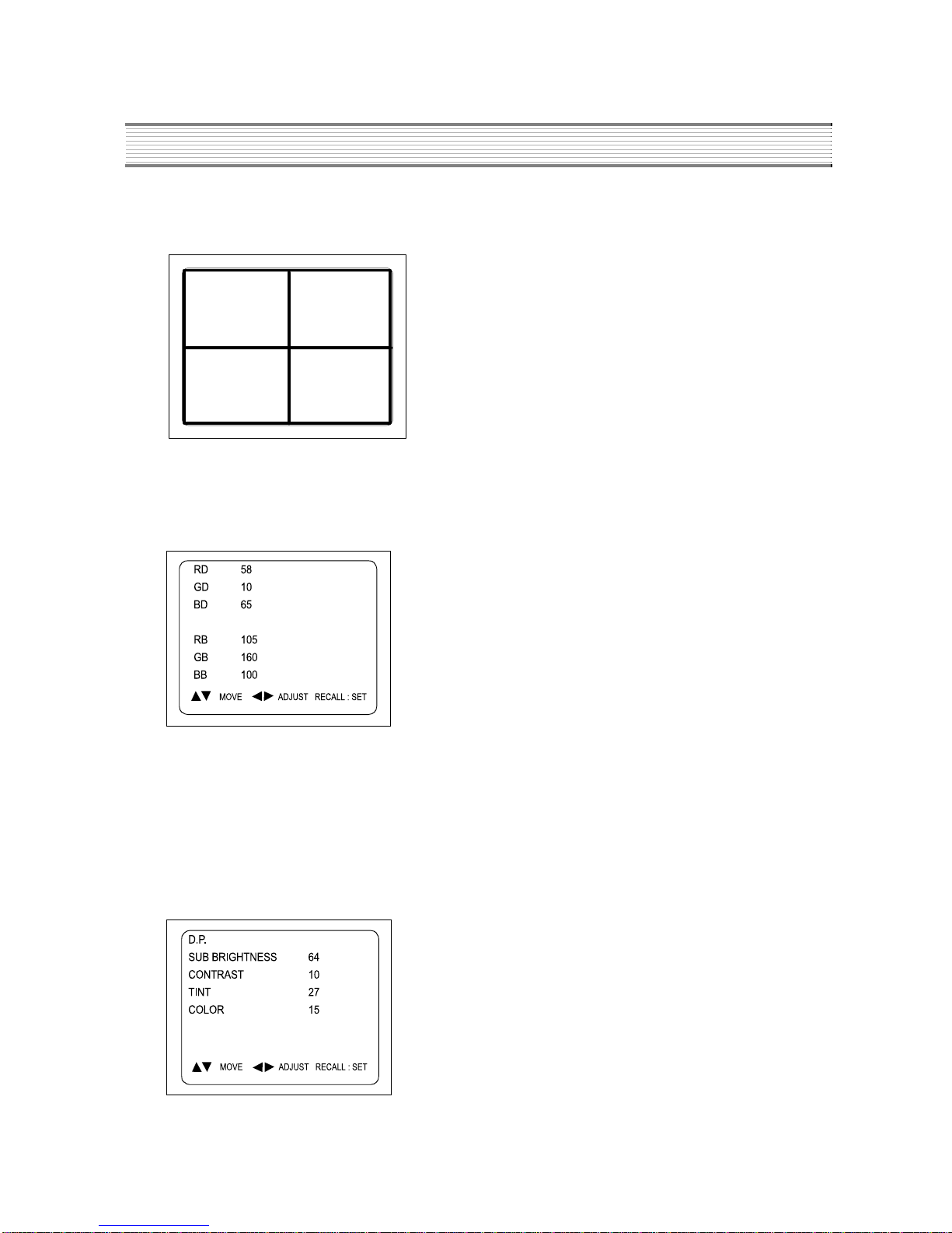
Red Drive (RD) *0~127 Align RED OUT Ievel
Green Drive (GD) 10 0~15 Must be set to 10
Blue Drive (BD) *0~127 Align BLUE OUT AC level
Red Bias (RB) *0~255 Align RED OUT DC Ievel
Green Bias (GB) *0~255 Align GREEN OUT DC Ievel
Blue Bias (BB) *0~255 Align BLUE OUT DC Ievel
Subbrightness *0~127 Align common RGB DC level
Contrast 10 0~27
Tint 27 0~27
Color 15 0~27
S12 ForwardingMode - FactoryInitialization
MODE ADJUSTMENT ITEMS REMARKS
S5
S6
S7
S8
S9
* indicates the items with different settings each of sets
ASSEMBLY ADJUSTMENTS
1) SCREEN ADJUSTMENT (S2)
Enter the service mode and select service adjustment S2.
You cna see the one horizontal line on the screen.
Adjust the Screen ControlVolume (located on FBT) so that the horizontal line onscreen may be
disappeared.
Press the volume up or down button to exit in the screen adjustment mode.
NOTE
IN THE SCREEN ADJUSTMENT MODE, DONT PRESS OTHER BUTTONS EXCEPT VOLUME UP OR DOWN BUTTON.