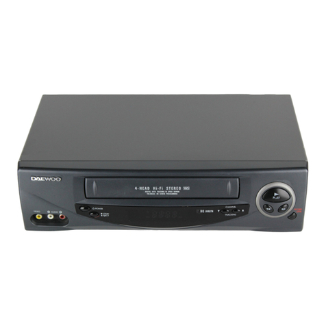
Daewoo DV3K653NZ-T User manual

Service Manual
S/M No.:VK653NTEF0
Jun.2002
DAEWOO ELECTRONICS CO., LTD.
http : //svc.dwe.co.kr
TIME LAPSE VCR
Model:DV3K653NZ-T
✔
Caution
: In this Manual, some parts can be changed for improving, their
performance without notice in the parts list. So, if you need the
latest parts information,please refer to PPL(Parts Price List) in
Service Information Center (http://svc.dwe.co.kr).

1
TABLE OF CONTENTS
SAFETY&PRECAUTIONS ............................................................................................... 2
EXTERNAL VIEWS ........................................................................................................ 4
FRONT VIEWS FUNCTION ...................................................................................................................4
REAR VIEWS FUNCTION .....................................................................................................................5
ELECTRICAL ADJUSTMENT ........................................................................................... 6
SPECIFICATIONS ....................................................................................................... 7
TIMELAPSE REC/PB SPEED CHART
................................................................................ 9
CIRCUIT OPERATION .................................................................................................. 10
RS-232C .................................................................................................................... 15
TROUBLE SHOOTING FLOW CHART ............................................................................. 27
POWER CIRCUIT ................................................................................................................................27
SERVO-SYSCON CIRCUIT ...................................................................................................................29
u-COM PORT DESCRIPTION ....................................................................................... 38
VOLTAGE CHART ....................................................................................................... 41
CIRCUIT DIAGRAM ..................................................................................................... 45
CONNECTION DIAGRAM ..................................................................................................................45
POWER CIRCUIT DIAGRAM ................................................................................................................46
SYSCON CIRCUIT DIAGRAM ..............................................................................................................47
A/V CIRCUIT DIAGRAM ......................................................................................................................48
OSD CIRCUIT DIAGRAM ....................................................................................................................49
LOGIC CIRCUIT DIAGRAM .................................................................................................................50
TERMINAL CIRCUIT DIAGRAM ............................................................................................................51
COMPONENTS LOCATION GUIDE ON PCB BOTTOM VIEW ........................................... 52
PCB MAIN .........................................................................................................................................52
PCB UNION .......................................................................................................................................53
PCB JACK .........................................................................................................................................54
DISASSEMBLY ............................................................................................................. 55
PANEL FRONT ASS’Y ...........................................................................................................................55
SET TOTAL ASS’Y .................................................................................................................................56
PACKING ASS’Y .................................................................................................................................57
ELECTRICAL PARTS LIST ............................................................................................... 58

2
SAFETY&PRECAUTIONS
SAFETY CHECK AFTER SERVING
Examine the area surrounding the repaired location for damage or deterioration. Observe that screw,
parts and wires have been returned to original positions. Afterwards, perform the following tests and con-
form the specified values in order to verify compliance with safety standards.
1. Insulation resistance test
Confirm the specified insulation resistance between power cord plug prong and externally exposed
parts of the set (RF terminals, antenna terminals, video and audio input and output terminals, micro-
phone jacks, earphone jacks, etc.)
is
greater than values given in table 1 below.
2. Dielectric strengthen test
Confirm specified dielectric strengthen between
power cord plug prongs and exposed accessible parts
of the set (RF terminals, antenna terminals, video and
audio input output terminals, microphone jack, ear
phone jacks, etc.) is greater than values given table 1.
3. Clearance distance
When replacing primary circuit component, confirm specified clearance distance (d), (d’) between sol-
dered terminals, and between terminals and surrounding metallic parts. See table below.
Rating for selected areas
* : Class model only
AC Line Voltage Region Insulation
Resistance Dielectric
Strength Clearance
Distance(d),(d)
100V Japan ] 1MΩ/500V DC 1kV AC 1min. ] 3
110 to 130V USA & Canada -900V AC 1min. ] 3.2
* 110 to 130V
200 to 240V
Europe
Australia
Latin America ] 10MΩ/500V DC 4kV AC 1min. ]6(d)
]8(d')
(a :Power cord)
This table is unofficial and for reference only. Be sure to confirm the precise values for your particular
NOTE

3
SAFETY&PRECAUTIONS
4. Leakage current test
Confirm specified or lower leakage current between
B(earth ground, power cord plug prongs) and externally
exposed accessible parts (RF terminals, antenna termi-
nals, video and audio input output terminals, microphone
jacks, earphone jacks, etc.)
Measuring method:(Power ON) Insert load Z between
B(earth ground, power cord plug prongs) and exposed
accessible parts. Use on AC voltmeter to measure across both terminals of load Z. See figure2 and
following table.
Leakage current ratings for selected are as
AC Line Voltage Region Load Z Leakage Current(
i
)Clearance Distance(d),(d’)
100V Japan 1kΩi*1mArms Exposed accessible parts
110 to 130V USA &Can-
ada 15kµF
1kΩi*0.5mArms Exposed accessible parts
110 to 130V
200 to 240V
Europe
Australia
Latin America
2kΩi*0.7mA peak
i*2mAdc Antenna earth terminals
50kΩi*0.7mA peak
i*1mAdc Other terminals
This table is unofficial and for reference only. Be sure to confirm the precise values
for your particular country and locality.
NOTE

4
1. FRONT VIEWS FUNCTION
EXTERNAL VIEWS
1) STOP button
2) REC button
3) REC CHECK button
4) EJECT button
5) CASSETTE LOADING DOOR
6) DISPLAY PANEL
7) PLAY button
8) REW button
9) FF button
10) PAUSE/STILL button
11) REMOTE SENSOR
12) VIDEO NOISE FILTER SWITCH
13) SET LOCK SWITCH
14) RESET button
15) MENU button
16) SHIFT( ) / TRACKING (-) button
17) SHIFT( ) / TRACKING (-) button
18) REC/PLAY SPEED (-) button (SET - button)
19) REC/PLAY SPEED (+) button (SET + button)
20) AUDIO ON button
21) DISPLAY button
22) STANDBY/ON button
23) COUNTER button
24) CLEAR button

5
EXTERNAL VIEWS
2. REAR VIEWS FUNCTION
1)AC POWER CORD
2)WARNING OUT terminal
3)SERIES IN terminal
4)COM terminal
5)SERIES OUT terminal
6)SW OUT terminal
7)VIDEO OUT jack
8)VIDEO IN jack
9)AUDIO IN jack
10)TAPE END terminal
11)PANIC IN terminal
12)COM terminal
13)ALARM OUT terminal
14)ALARM IN terminal
15)MIC (microphone input) jack
16)AUDIO OUT jack
17)RS232C

6
ELECTRICAL ADJUSTMENT
1. SERVO/SYSCON CIRCUIT ADJUSTMENT METHOD
v
VIDEO HEAD SWITCHING POSITION
v
CONNECTION METHOD
v
ADJUSTMENT PROCEDURE
1) Play back the test tape.
2) Set the oscilloscope in the chop mode connect the CH1 to SW pulse(PT501 (r)PIN), the CH2 to
TJ396(video out) with CH1 triggering.
3) Adjust R595 for the positive trigger until 6.5 ±0.5H cycle before the vertical SYNC pulse.
Adjustment Part Checking Point Measuring Equipment Mode Test Tape
R595 TJ396
PT501 PIN3 OSCILLOSCOPE Play DN-1 (Color Bar)
TJ396
CH-1
Oscilloscope
CH-2
PT501 R595
CH1 SW PULSE
(PT501 3PIN)
VIDEO OUT
(TJ396)
Vertical SYNC Signal
1H
6.5H 0.5H
Trigger Position

7
SPECIFICATIONS-I
40Hours Real Time Record Mode with T-160 Tape (20 field-per second with T-160 Tape)
8000Hour Lifetime guarantee Ball Bearing CAPSTAN MOTOR Mounting
DIGITAL SHUTTLE function( REVERSE PLAY & REVERSE SLOW)
RS-232C COMMUNICATION PC INTERFACE
Up-to 1280 Hours Recording (T-160 Tape)
Super Clear Picture
- Over 350 Lines Horizontal Resolution(B/W)
- Over 300 Lines Horizontal Resolution(Color)
Various Emergency Record Mode
DLC Coating Drum for Long-Time Record
Various Record Search
Alarm Search
Index Search
Zero Search
Simple Controls by Menu Selection Daily timer program, Weekly timer program, Terminal
input setting, Characters Location and Text input
function.
Self-Diagnosis E-1, E-2, E-3, E-4
Compact size for installation or moving.

8
SPECIFICATIONS-II
Video Signal system NTSC
REC/PB System Helical scanning system
Tape Width 12.65mm (1/2 inch), VHS
Record system of Luminance Signal Frequency modulation record
Record system of Color Signal Down converted subcarrier phase shift system
Tape Speed (T-120) 2H : 33.35mm/s (SP), 6H : 11.12mm/s(EP),
18H : 3.71mm/s, 36H : 1.85mm/s
Record/Play Time (T-120) SP:2/48/72/96/120/168/240/360/480/720/960H,
EP:6H/18H/30H (PLAY)
FF/REW Time (T-120) Within 3 minutes
Video Signal Input 1.0Vp-p 75Ω, unbalanced
Video Signal Output 1.0Vp-p 75Ω, unbalanced
Luminance Signal to Noise ratio SP : Minimum 45dB, EP : Minimum 41dB
Horizontal resolution Mimimum 350 Lines (B/W), Minimum 300 Lines (Color)
Audio Signal Input Line Input -8.8dBm (1KHz), 47KΩminimum
Audio Signal Output Line Output -7.8dBm (1KHz), 1KΩmaximum
Audio Signal to Noise Ratio (A.Weighted) SP : 42dB minimum VHS, EP : 40dB minimum VHS
Audio Frequency Range SP : 0+3, -6dB [100Hz~10KHz] VHS, EP : 0+3, -6dB [100Hz~5KHz] VHS
Distortion SP : 4% maximum VHS, EP : 5% maximum VHS
WOW Flutter SP : 0.3% maximum VHS, EP : 0.4% maximum VHS
Alarm input DC 4~5V (open), DC 0~0.8V (closed) / 5.7kΩ
Alarm output DC 4~5V (High), DC 0~0.8V (Low) / 5.7kΩ
Panic input DC 4~5V (open), DC 0~0.8V (closed) / 5.7kΩ
End output DC 4~5V (High), DC 0~0.8V (Low) / 5.7kΩ
Warning output DC 4~5V (High), DC 0~0.8V (Low) / 5.7kΩ
Series input DC 4~5V (High), DC 0~0.8V (Low) / 5.7kΩ
Series output DC 4~5V (High), DC 0~0.8V (Low) / 5.7kΩ
Switch output DC 4~5V (High), DC 0~0.8V (Low) / 5.7kΩ
Common GND
Microphone Input -60dBs 3.5mm mini Jack 10k ohm, unbalanced
Accuracy of Timer Within 2 seconds per day
Compensate Time for Power Fail About 1 Month
Power Supply AC 90~240V(free voltage), 60Hz
Power Consumption 17W
Operation Temperature
°°
41 F ~ 104 F(Humidity : under 80%)
Storage Temperature
Dimension (W x H x D) 360 x 90 x 289
Weight Approximate 4.0 Kg (NET)
- 4 F ~ 140 F
° °
9
TIMELAPSE REC/PB SPEED CHART
TAPE MODE TAPE SPEED REMARK
REC
MODE
T-120
SP 2H 48H 72H 96H 120H 168H 240H 360H 480H 720H 960H
EP 6H 18H 30H
T-160
SP 2.7H 64H 72H 128H 160H 224H 320H 480H 640H 960H 1280H
EP 8H 24H 40H
PLAY
MODE
T-120
SP 2H 48H 72H 96H 120H 168H 240H 360H 480H 720H 960H
EP 6H 18H 30H
T-160
SP 2.7H 64H 72H 128H 160H 224H 320H 480H 640H 960H 1280H
EP 8H 24H 40H
AUDIO POSSIBLE NOT POSSIBLE

10
CIRCUIT OPERATION
1. SERVO SYSCON PART
1-1) BLOCK DIAGRAM
DRUM
PG FG AMP CAPSTAN
SPEED CTL
IC501
M37775M5H
u-COM
PROCESSOR
Start end
SENSOR
&
REEL
SENSOR
LOADING
CAM DRIVE
CTL
AMP
VIDEO
BLOCK AUDIO
BLOCK TERMINAL
BLOCK
BACK
UP BATT
Vcc OSC&
RESET
<K682N-T/U SERVO SYSCON BLOCK>

11
CIRCUIT OPERATION
1-2) TIME LAPSE RECORDING METHOD
The numbers of VHS 2HOUR (SP), 6HOUR (EP) REC FIELD are 60 field/sec, then it will be 1FRAME =
33.3Ms, 1FIELD = 16.65Ms.
CAPSTAN MOTOR FG numbers for Time Lapse are 6HOUR(EP) = 720 numbers/sec, 2HOUR(SP) =
720*3=2160 numbers/sec.
uu-COM controls capstan motor (C I LIMIT) with capstan motor FG numbers. DRUM HEAD ON/OFF
controlled by HEAD AMP SW & REC mute signal.
uu-COM controls capstan motor (C I LIMIT) with capstan motor FG numbers. DRUM HEAD ON/OFF
controlled by HEAD AMP SW & REC mute signal.
LRLRLRLRLRLRL
16.65ms
18H(EP) RECORDING (20FIELD/SEC)
2H & 6H (60FIELD/SEC)
LRLRL
33.3ms
18H (20FIELD/SEC) : Recording 1 field per 3 fields
(Capstan FG numbers are ; 1SEC:720=33.3ms:X X=24)
(Capstan FG numbers are ; 1SEC:720=16.65ms:X X=12)
LRLRLRLRLRLRLRLRLRLRLRLRL
16.65ms
48H(SP) RECORDING (2.5Field/SEC)
: recording 1 field per 24 fields
LR
16.65ms*22=366.3ms
18H (20FIELD/SEC) : Recording 1 field per 3 fields
(Capstan FG numbers are ; 1SEC:2160=366.3ms:X X=791)
(Capstan FG numbers are ; 1SEC:2160=16.65ms:X X=35)

12
CIRCUIT OPERATION
1-3) TERMINAL PART
ALARM INPUT
Connect DOOR SW&SENSOR etc and this port will be used for emergency recording by using open/
close status.
ALARM OUTPUT
This port is always triggered during ALARM REC, which is used to inform the outside that time lapse
VCR is now performing Alarm Recording.
uTrigger Time will be the set time on MENU, it will be approximately 2 minutes at least.
PANIC INPUT
This is the first priority REC, then operation is similar as Alarm Rec. But if Panic Recording is triggered,
the set stops all kinds of Recording then starts recording with 2H(SP) mode at the end of tape.
5V
0V 500ms
500ms
N/O(NORMALY OPEN)
N/C(NORMALY CLOSED)
0V
5V
0V Minimum 2mins. Minimum 2mins.
HIGH LOW
5V
0V 500ms 500ms
N/CLOSED N/OPEN
5V

13
CIRCUIT OPERATION
TAPE END OUT
When the recording tape ends during recording, end sensor will be detected. This port is used Alarm to
outsider until release the end sensor detecting.
SW OUTPUT
This port is used triggering video signal with external equipment during recording.
SERIES OUTPUT
When the series recording proceeds after setting the series recording to “on”, this port is used to output
the control signal to the set which will be recorded continuously after pre-recording set.
0V
END Detect END Detect
HIGH LOW
5V
10msec
SW
OUT
2FIELD
16.67ms
SW
OUT
1FIELD
VIDEO
SIGNAL
0V 250ms
5V

14
CIRCUIT OPERATION
SERIES INPUT
When the series recording proceeds after setting the series recording to “on”, this port is used to receive
the control signal to the set which will be recorded continuously after pre-recording set.
WARNING OUTPUT
This port is used to inform emergency status of Time Lapse VCR Set to outsider.
0V 200ms
5V
0V EMERGENCY
status term
500ms
HIGH
LOW
5V
0V
5V

15
INTERFACE(RS-232C)
9-pin connector layout
•The signal transmission is compatible with RS-232C specifications.
VCR pin number Computer pin number
• To make the cable, the connection of connector pin is followed above.
Caution1) Make the end parts of cable connector to be female.
Caution2) The arrowhead mark indicates the signal flow.
Operating System for installation of SECUNET SW
•32Mbytes memory is needed in minimum.
•PC OS System
- Windows 95, Windows 98, Windows 98 SE,
Windows ME, Windows 2000, Windows NT
Pin number Signal Operation Signal direction
2RXD Receive data VCR Computer
3TXD Send data VCR Computer
7RTS Request to send VCR Computer
5GND Signal ground
RS-232C
Secunet V1.0
RS232C COMMUNICATION
PC INTERFACE PROGRAM
15mm
37mm
120mm

16
SECUNET SW INSTALLATION
1. This will install SECUNET on your computer.
It is recommended that you exit all other programs
before proceed with installation. Click <Next> to
continue installation.
Or, click <Cancel> to cancel installation.
RS-232C

17
2. This will be installed to following folder.
Click <Install> to begin installation to following folder.
To install to a different folder, Either enter install path, Or, click <Browse> and select
another folder. space needed: 3,915bytes.
RS-232C

18
3. Update your file in the screen above and click <Yes>,
4. To complete installation, system must be restarted. Click<Yes>.
RS-232C

19
5. Click <Confirm>.
Connect TimeLapse VCR with PC
Necessary articles
•232C Serial Cable (9 pin)
•Personal Computer
•TimeLapse VCR
How to connect
•Connect 232C Serial Cable to Com1 of Personal Computer .
Problem & Solution
If the communication
speed of this set isn’t
equal with that of
Personal Computer, this
set won’t be operated
properly.
RS-232C
Press RESET button of this set and
turn off the timelapse SW. Then
turn on it again.
Make the TimeLapse SW speed be
equal with this set. Set the
communication speed by clicking
“setting fulldown menu” in
timelapse operation screen.
Table of contents
Other Daewoo VCR System manuals

Daewoo
Daewoo DV-T27N User manual

Daewoo
Daewoo DVK-87N User manual

Daewoo
Daewoo T150W User manual

Daewoo
Daewoo ST120W User manual

Daewoo
Daewoo Video recorder User manual

Daewoo
Daewoo DV-T8T2NZ-QB/M User manual

Daewoo
Daewoo DV-T6F4N-PQ User manual

Daewoo
Daewoo DV-K486N User manual

Daewoo
Daewoo DV-S137WN User manual

Daewoo
Daewoo DV-S103W Series User manual

Daewoo
Daewoo Q817 User manual

Daewoo
Daewoo DV-K882SY-AN User manual

Daewoo
Daewoo DVR-5088N User manual

Daewoo
Daewoo SD-6200D Assembly instructions

Daewoo
Daewoo DVST1C1WX-BG/D User manual

Daewoo
Daewoo DV-K*84W Series User manual

Daewoo
Daewoo K50 User manual

Daewoo
Daewoo DV- K584N-SJ User manual

Daewoo
Daewoo DV-F24J User manual

Daewoo
Daewoo DV-K884N-SJ User manual