dafi Flow Comfort DC10 Lead User manual

100%
Polish
Brand
TAP WATER
filtration system
Flow Comfort DC10 Lead
*Brand most frequently recommended and purchased among water ltering products. Source: Formaster S.A. based on
a survey conducted by Difference, nationwide sample of N=1000 people aged 18+, using CAWI method, December 2022.
*

2
Table of contents
Specification
Safety of use - important information
Technical details of the filtration system
Instalation
Turning on the system
Replacement of the D10 Lead filter cartridge
Maintenance
Filter Replacement Indicators
Flow Meter User's Manual
Technical specifications of the Flow Meter
Instructions on disposal and environmental protection
Terms and conditions of the warranty
3
3
3
4
7
7
8
8
11
12
12
13

3
•The compact construction of the filter allows for perfect optimization of tap water by reducing the
content of lead, chlorine and undesirable substances. The use of the Flow Comfort filtration system
improves the taste of drinking water. Water becomes clear and suitable for direct consumption. The
elements of the system are adjusted for installation in a cabinet under the sink. The efficiency and
durability of the filter depend on the local properties of water as well as on the condition of the water
installation.
•The filter bed has been developed based on a high-quality activated carbon of natural origin. It is
possible that carbon particles might appear in the water. They are completely safe for health. If
swallowed, they will cause no harm to health. The construction of the filtration system uses materials
approved for contact with food.
•The Flow Comfort system includes an independent or integrated electronic indicator which reminds
the user about the need to replace the filter.
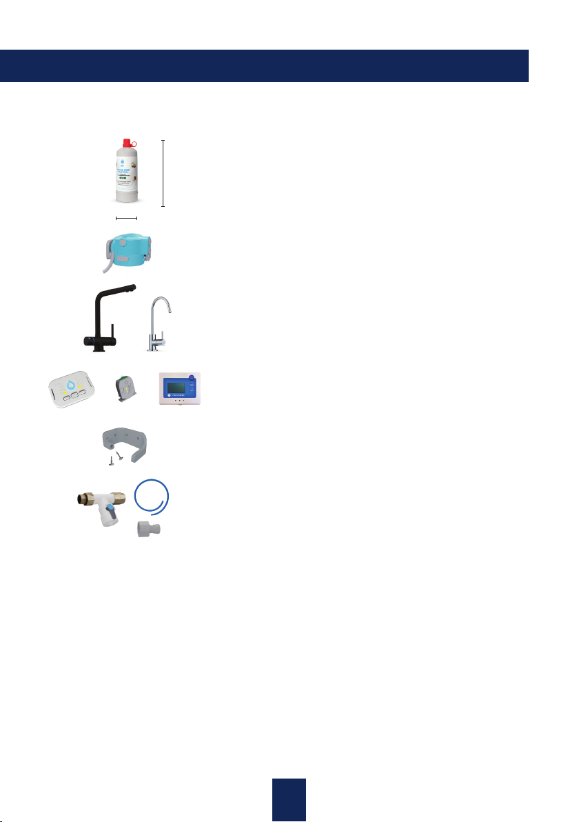
Specification
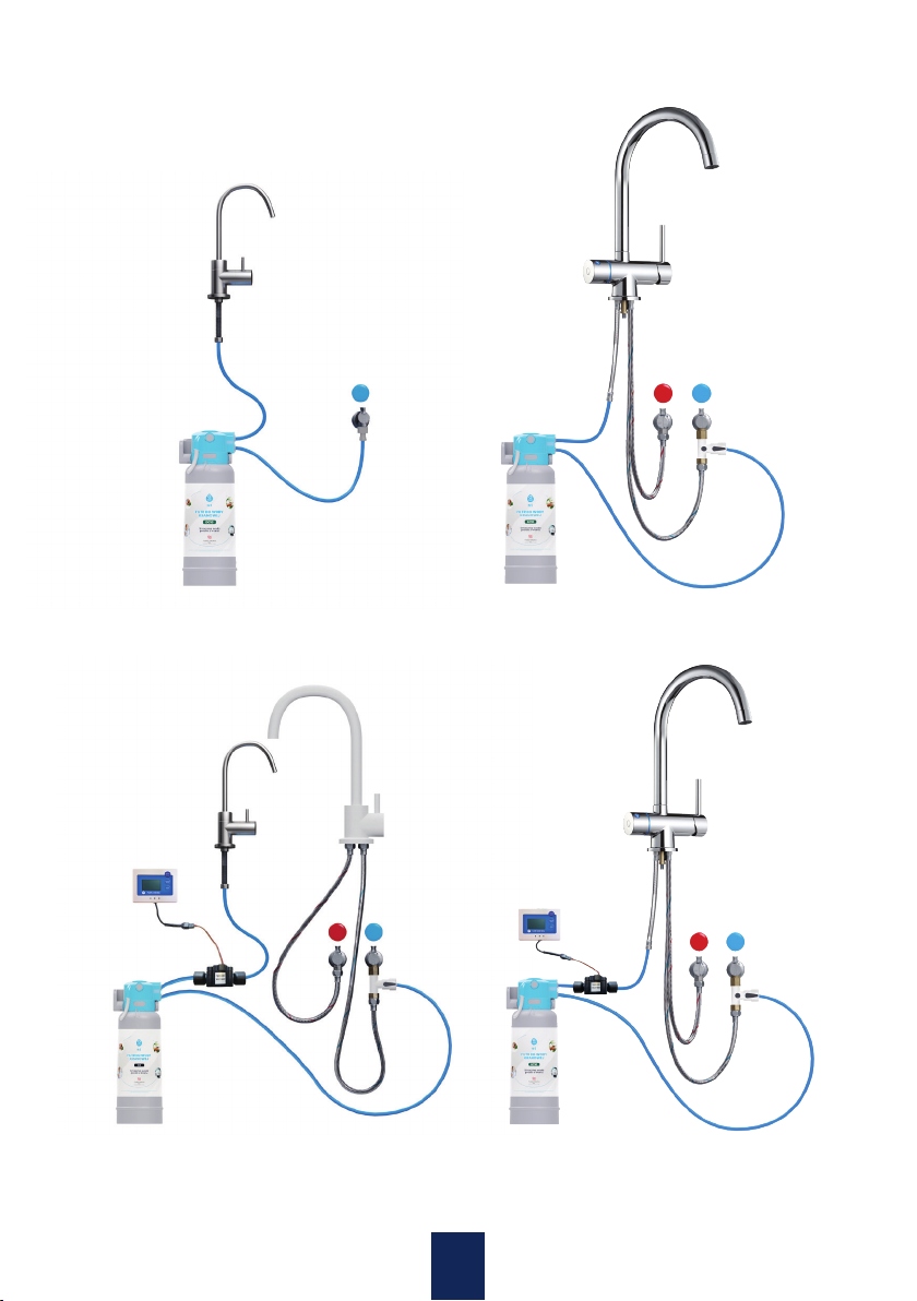
•The tap water filtration system can be connected to the cold drinking water connection. Do not use for
water that has not been analyzed for suitability for consumption.
•A shut-off valve should be installed before the filter.
•If water pressure is higher than the nominal value, a pressure-reducing valve must be installed.
•Certain groups of people e.g., people with kidney diseases or weak immune system should consult the
possibility and method of use of the filter with a specialist and/or a physician.
•It is recommended that the filtration system should not be left unused for a longer period of time. If the
system is not used for 2-3 days, flush it with 0.52 gallon of water. If the system is going to be used for
the first time after a month or longer, flush it with 5.2 gallons of water.
•Filtered water remains suitable for consumption for 1-2 days (depending on the storage conditions).
•Due to the risk of secondary pollutants in the water installation, the system has been qualified as
category 2 acc. to EN 1717.
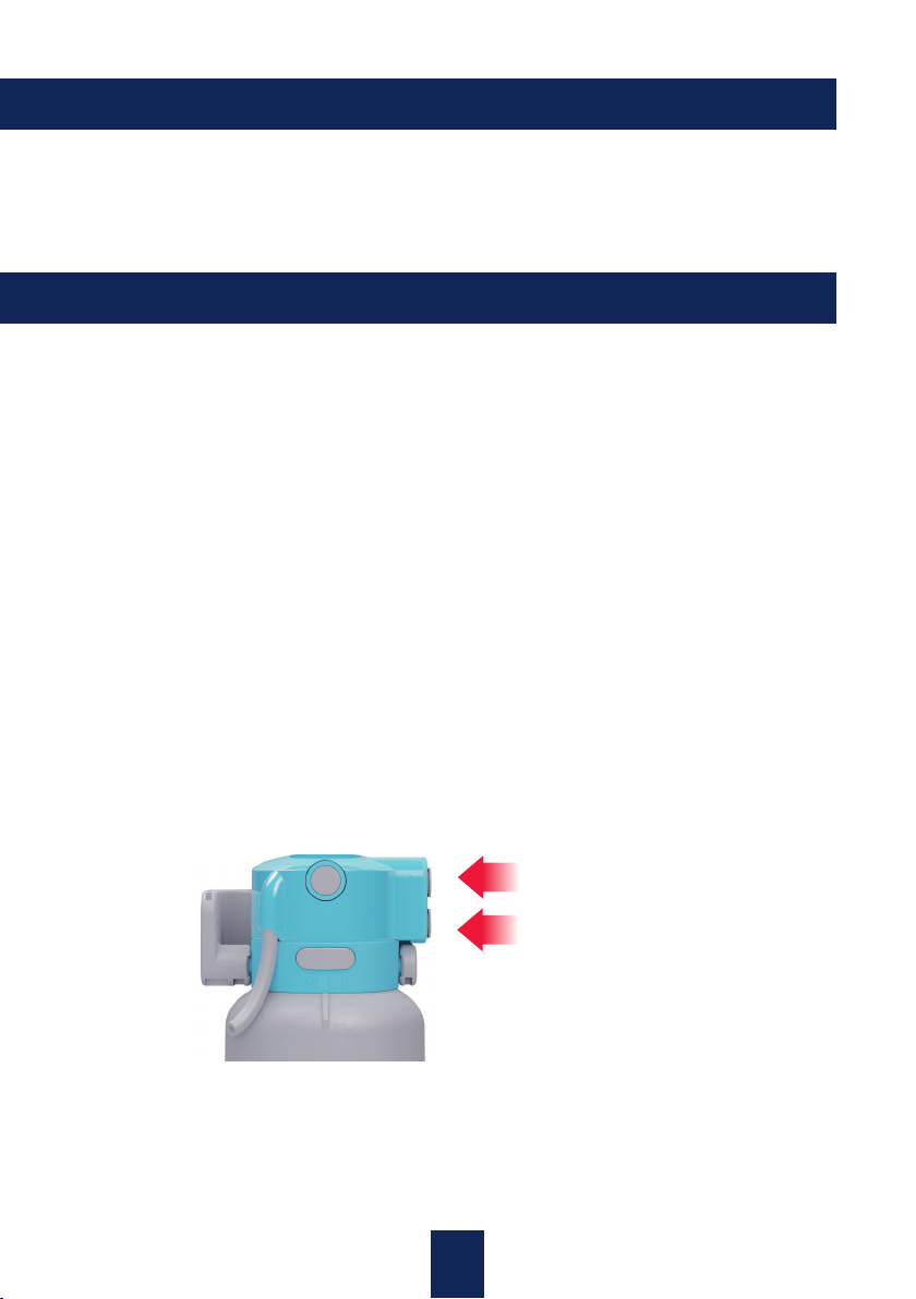
•The DC10 Lead filter cartridge and the head must be protected against overheating and excessive
exposure to sun.
•A factory-packed D10 Lead filter cartridge is fit for use for 5 years from the date of manufacture.
Safety of use - important information
Working pressure 11.6 - 87 PSI
Maximum working pressure (if higher, use a pressure-reducing valve) 116 PSI
Temperature of feed water 39.2°F (4°C) to 86°F (30°C)
Ambient temperature during storage and transport 5°F to 104°F
Water flow Pressure in the water installation
0.8 US gal/min (gpm) 29 PSI
1.1 US gal/min (gpm) 44 PSI
1.2 US gal/min (gpm) 58 PSI
Dimensions of the filter with the head and the wall bracket 4,3 x 4,3 x 11,4 inch
Position of installation Vertical
Water connection - inlet and outlet ¼ ‘’ (6.3 mm) hose
Technical details of the filtration system

4
Instalation
Contents of the packaging
One DC10 Lead filter cartridge that reduces the content of lead,
chlorine and undesirable substances. It improves the taste and
smell of drinking water.
Head of the filter cartridge
3-way faucet or filtered water faucet
Integrated, independent or flow meter filter replacement indicator
Bracket and screws for installation on the wall
10.83"
4"
T-pipe, flexible hose, adapter
Notes
•Thanks to the easy installation and intuitive method of connecting the Flow Comfort filtration system,
the whole process can be carried out by the user on their own, following the instructions in this ma-
nual. In case of any doubts, difficulties or lack of proper tools, the connection of the system should be
entrusted to a certified specialist.
•Before the installation of components of the system, check the components of the connection for
visible damage or lime. If necessary, clean or replace the components.
•The installation of the Flow Comfort filtration system must be carried out in line with applicable local
regulations on installations of drinking water.
•The filter can be freely placed on the floor or suspended on the wall bracket so that the hoses remain
loose.
•Installation of the faucet is carried out in accordance with the enclosed installation instructions inc-
luded in the kit.
or
or or
The contents of the package depend on the selected variant.

5
Connecting the head with the filter cartridge
Just before snapping the filter cartridge in the head, remove the protective cover.
To remove the protective cover:
Tear off the protection Remove the cover
The deaeration hose, which is a part of the head, should be loosely led out and be outside of the head.
Press the head onto the filter cartridge in a firm motion,
pressing the entire surface evenly, so that no gap remains between
the filter, and the head. When installing the head, the cartridge is best
placed on a stable surface, for example: the bottom of the cabinet or
on the floor. Make sure that the locking button is as extended as it was
before the head was connected to the filter. (pic.1)
Set the filter in position D.
pic. 1

6
Connecting the filtration system to the water installation
•Connecting the filtration system to the water installation of the building must be carried out in accor-
dance with the standards applicable at the particular location. In case of any doubts, the installation
should be carried out by a qualified specialist.
•Divide the flexible hose into two parts, which will be used to connect the system to the water system.
•The filtration system is connected to the water installation with ¼” (6.3 mm) water hoses by inserting
the hoses into quick-release couplings in the head.
•The places for connection of the water hoses are marked on the head with arrows that indicate the
water inlet and outlet.
•Depending on the type and size of the cold drinking water connection, there are several methods to
connect the inflow hose.
In order to connect the inflow hose, use one of the connection elements adjusted for ¼”
(6.3 mm) water hoses on the water intake.
Angular stop valve with a check valve, 3/8” thread and quick-release coupling for a 1/4” water hose
•allows snapping the 1/4” water hose in the place of connection of the
flexible hose cold water faucet
•protected against return outflow from the filter
•the quick-release coupling makes connecting the 1/4” hose fast and
easy
•Connection of the water hoses for filtered water must be carried out according to the manual of the
used water intake device.
Installation of the wall bracket
•The wall bracket is installed with two
screws properly chosen for the type
of wall e.g., 3.5 Pz screws in case of a
furniture board. The bracket should be
installed in a way that provides enough
space for the filter cartridge.
option 1 option 2
Connecting the filter head to the bracket
2. Slightly deflect the opposite arm
of the bracket. Snap the head
by inserting the protruding
piece of the head into the hole.
3. Make sure that the head
is firmly positioned in the
bracket.
1. Slip the connecting piece of the
head into the opening of the
bracket on the right side.
1.
2.

7
Examples of connection

8
•Take off the cover of the neck from the new filter cartridge. The cover can be put on the used filter to
prevent the water from leaking.
•Then follow the same steps as for installing a new filter cartridge in the head (see page 5) and run
according to the instructions on page 7.
•The head of the filter has protection against flooding: without the filter cartridge, water will not flow
through or out of the head.
•Shut off the supply of water to the system.
•Place a container for leaking water under the hose and the filter and press then release the round
deaeration button in order to reduce the pressure in the system.
•Press the elongated lock button of the filter cartridge and remove the cartridge. If you have difficulties
in removing the cartridge, twist it firmly right or left and then remove.
•Unplug the head together with the filter cartridge from the mounting bracket.
Lock button
Deaeration button
Instructions for replacement of the D10 Lead filter cartridge
Replacement of the D10 Lead filter cartridge
The water filter must be replaced if at least one of the following situations happens:
•The taste or smell of filtered water is deteriorating.
•The efficiency specified by the manufacturer (793.5 US gal) is reached.
•6 months lapsed from the date of installation of the filter.
•Regardless of decreased pressure in the water installation, there is a noticeable decrease in the
pressure of the outflowing water.
•The electronic indicator signals the use period after which the effectiveness of filtration will decrease.
Note
If the product is stored or transported in temperature below 39.2°F, it should be left in room temperature
in opened packaging for at least 24 hours before installation.
Turning on the system
1. Before turning on the water supply, make sure that all the installation steps have been carried out
correctly and all elements of the system have been properly connected.
2. Turn on filtered water on the tap.
3. Turn on the water supply, make sure that there are no leaks and let the water flow through until it
becomes transparent and devoid of air.

9
Manual for the independent filter cartridge replacement indicator
The independent indicator (faucets: COMO, KYOTO ALTO, ALTO+)
HARD - button to set the
water hardness*
*DOES NOT REFER TO DC1 AND DC10 LEAD FILTERS.
LED - Filter cartridge
type indicator
SIZE - button for setting
the type of filter used
LED - signaling diode
CHECK/RESET:
- postponing the blinking
- blinking/beeping for 12 hours
- RESET
Filter Replacement Indicators
The integrated indicator (faucets: VITO, HERO)
RESET - Button to reset
and activation of work
indicator
LED SIZE/HRD - signaling
diode of type of cartridge
and hardness level water*
SIZE - Button for setting
the type of filter used
HRD - Button for setting
level of hardness WATER
A, B, C, D*
LED - Diode signaling
filter wear status
•On a regular basis, check whether the system is leakproof and the hoses are not bent. If bent, the
hoses must be immediately replaced.
•Do not use aggressive cleaning agents, abrasive substances or cleaning solutions.
Maintenance

10
Mounting
If you want to attach the indicator to a non-metal surface (e.g. furniture board, wall, plastic), remove the
film from the stickers on the mounting plate and attach to surface, then connect the indicator to the
mounting plate.
If you want to attach the indicator to a ferromagnetic metal surface (that is attracted by a magnet),
attach it without the back plate; the indicator will be attached thanks to the magnetic properties.
Functions of the multifunctional CHECK/RESET button:
By short-pressing the key (for 1 sec): check the status of the filter cartridge, which is signaled in the
following way:
•blue blinking diode: filter cartridge active,
•yellow blinking diode and 3 series of beeps every 2 hours: you have 7 days to replace the filter car-
tridge,
•red blinking diode and 3 series of beeps every 1 hour: replace the filter cartridge with a new one,
•when the reminder on the need to replace the filter cartridge is on, you can postpone the blinking/
beeping by 12 hours by short-pressing the “CHECK/RESET” button.
Long press (4 sec):
It resets the usage period of the filter cartridge and saves the current settings.
Once the filter size and water hardness have been set, press and hold the CHECK/REST button for 4
seconds to save the settings. If the parameters are not saved after changes, the previous settings will
be restored after 1 minute.
Removal of batteries will not reset the settings.
When the selected type of filter cartridge is DC10 Lead, there is no option for choosing the hardness
(signaled by blinking LED water hardness indicators).
Settings:
SIZE: Type of the filter cartridge
•D1
•D2
•D3
•DC10 Lead

11
Flow Meter User's Manual
Application
Water treatment system
SENSOR INSTALLATION IS CARRIED OUT BY THE INSTALLER
Installation of power supply batteries
Slide off the battery compartment cover from the side of the flow meter housing, slide out the basket
and insert the into it two AA alkaline batteries maintaining the correct polarity. Then slide the basket and
replace the cover. The capacity of two AA alkaline batteries is enough for two years of normal use.
Programming the filter performance monitoring
Press the "PROG" button, "PROG" will flash on the LCD display. Then press "RESET" to select the appropria-
te value to store the right digit. After selecting the value press the "PROG" button to save the value and
move to the next digit. Repeat the above procedure procedure to program values for five digits from right
to left. The maximum value for Flow Meter monitoring is 99999 liters. Completion of programming, the
meter will signal with a beep * If no button is pressed for one minute during programming, the procedure
will be terminated and the meter will return to its original state.
After replacing the filter cartridge with a new one, press the RESET button briefly.The display will show
the current state of the counter. Then press the RESET button again for about 5 seconds. The counter
will start monitoring the performance of the new filter.
Operation
Flow Meter automatically turns on and displays the remaining capacity when water flows through the
sensor and automatically turns off after 10 seconds when water is not flowing.
Filter consumption alarm
Flow Meter generates an audible alarm and the digits on the LCD display flash when the remaining
capacity reaches zero or minus. The alarm will be generated every time water flows through the sensor.
Resetting
Press the "RESET" button for three seconds, "RESET" on the LCD will flash twice, and the remaining
capacity is reset to the original programming value

12
Technical specifications of the Flow Meter
Water flow rate 0,05-1,32 gal
Water flow measurement 1-99999 gallons
Power supply 2 AA alkaline batteries
Connection 1/4" BSP male
Working temperature 32-170oF
Working Pressure Max. 112 psi
Weight 5.38 oz
Accuracy +/- 5%
Length of electric cable to flow sensor 5 feet
Repeatability of the system 1 %
Low battery warning
When the battery capacity level is low, the Flow Meter generates an audible alarm, and a flashing empty
battery symbol appears in the upper right corner of the LCD display. The alarm will be canceled when the
batteries are replaced with new ones. Replacing the batteries does not cause the meter to lose status
of the meter.
If the device, packaging, operating manual, etc. is marked with a symbol of a crossed wheeled wa-
ste bin, it means that it is subject to selective collection. The symbol of a crossed container on a
device, packaging or manual informs that the electrical or electronic device, after its lifetime, must
not be disposed with other household waste. It is forbidden to dispose of the device as mixed solid
waste since it is classified as waste that can be harmful to the environment. The user is obligated
to hand over the used device to a point of selective collection of electrical equipment and in accor-
dance with local regulations. Improper disposal of this product can be subject to penalties under
domestic regulations of law.
Disposal of batteries
The product requires batteries described in the contents of Directive 2006/66/EC - 2XLR03
(IEC), AAA (ANSI), which must not be disposed of with other household waste. Read the local
regulations regarding disposal of batteries since their proper disposal prevents loss of health
and pollution of the natural environment
Protection of the environment
The manufacturer has made all the effort to eliminate redundant packaging. The used packaging
can be more or less divided into three groups: cardboard (box), polystyrene foam (side protective
elements) and polyethylene (plastic bags, protective foil). The device was made from materials that
can be recycled and reused by specialist facilities. Please read the regulations applicable in Poland
and your local regulations within the scope of disposal of packaging, discharged batteries and used
electronic devices.
Instructions on disposal and environmental protection

13
Dafi LLC
601 N Congress Ave
Ste 201
Delray Beach, FL 33445
e-mail: support@dafi.us
tel: 561-717-6782
The warranty does not cover:
•damage/defects that result from use, maintenance or storage against the instructions in the
operating manual of the Product;
•mechanical, thermal, chemical damage caused (after handing over the Product to the Customer) by
external factors i.e., due to reasons not connected with the Product itself;
•damage resulting from faults that were identified by the Customer and left unrepaired;
•results of repairs, alterations or design changes made by unauthorized entities;
•damage resulting from improper assembly - against the instructions of the manual -
or installation of incorrect parts or accessories by unauthorized entities;
•damage caused (after handing over the Product to the Customer) due to force majeure (e.g. flood,
fire) i.e., due to reasons not connected with the Product itself;
•the Product, if the replaceable filter cartridge that lost its filtration properties was not replaced at the
right time.
The warranty will become invalid when:
•damage results from situations described in section 6 “The warranty does not cover”;
•mechanical interference, alterations or other changes in the design were made by unauthorized
entities.
Terms and conditions of the warranty
1. This warranty refers to the Flow Comfort filtration system (hereinafter referred to as the “Product”)
purchased online by the Customer within the territory of the United States of America.
2. The product is covered by a warranty for factory defects and faults and is valid for 24 months from
the date of purchase.
3. The warranty shall remain valid only when the Customer complies with all the instructions provided
in the operating manual of the system.
4. In case of detected factory defects and faults, the Customer should contact the importer directly in
order to receive information on further proceedings:
Instructions on used DC10 Lead filter cartridges
“Keep it clean” - Remember to put the used product in a trash bin directly after use.
“Green point” - The manufacturer ensured proper processing of the packaging and also paid
for recycling of the materials that the packaging is made of.

14

15

Manufacturer:
Dafi LLC
601 N Congress Ave
Ste 201
Delray Beach, FL 33445
e-mail: support@dafi.us
tel: 561-717-6782
2023_xxx_xx
Data wykonania: 07.07.2023 roku.
Wersja: 2_DC10
Table of contents
Popular Water Filtration System manuals by other brands

HYDAC FILTER SYSTEMS
HYDAC FILTER SYSTEMS OF7 Operating and maintenance instructions

Pentair
Pentair PRESHPOINT GRO-350BP Installation and operation manual

Graco
Graco 244053 Instructions and parts list

BWT
BWT bestaqua 14 Fitting and operating instructions

SMC Networks
SMC Networks AFF50-06-D Operation manual

Geotech
Geotech Filter Bucket Installation and operation manual

Honeywell
Honeywell 50045947 Install and operation instructions

Filtreco
Filtreco Drum 100 user manual

Clarke
Clarke CAT191 Operating & maintenance instructions

GF
GF JRG 1830 Operating and maintenance instructions

norweco
norweco BIO-DYNAMIC LF 4600 Installation and operation manual

Klimawent
Klimawent ROBUST-1000 Use and maintenance manual