Dahua DHI-ASG2900C User manual

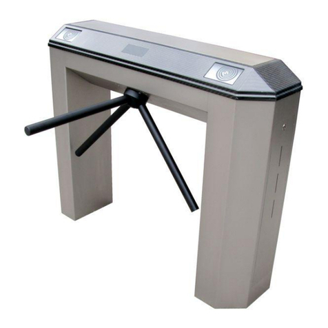
Tripod Turnstile
User’s Manual
V1.0.0

I
Foreword
General
This manual introduces the functions and operations of the tripod turnstile (hereinafter referred to as
the "turnstile").
Safety Instructions
The following categorized signal words with defined meaning might appear in the manual.
Signal Words Meaning
DANGER
Indicates a high potential hazard which, if not avoided, will result in
death or serious injury.
WARNING
Indicates a medium or low potential hazard which, if not avoided,
could result in slight or moderate injury.
CAUTION
Indicates a potential risk which, if not avoided, could result in
property damage, data loss, lower performance, or unpredictable
result.
TIPS Provides methods to help you solve a problem or save you time.
NOTE
Provides additional information as the emphasis and supplement to
the text.
Revision History
Version Revision content Release Time
V1.0.0 First release. February 2021
About the Manual
The manual is for reference only. If there is inconsistency between the manual and the actual
product, the actual product shall prevail.
We are not liable for any loss caused by the operations that do not comply with the manual.
The manual would be updated according to the latest laws and regulations of related jurisdictions.
For detailed information, refer to the paper manual, CD-ROM, QR code or our official website. If
there is inconsistency between paper manual and the electronic version, the electronic version
shall prevail.
All the designs and software are subject to change without prior written notice. The product
updates might cause some differences between the actual product and the manual. Please
contact the customer service for the latest program and supplementary documentation.
There still might be deviation in technical data, functions and operations description, or errors in
print. If there is any doubt or dispute, we reserve the right of final explanation.

II
Upgrade the reader software or try other mainstream reader software if the manual (in PDF
format) cannot be opened.
All trademarks, registered trademarks and the company names in the manual are the properties
of their respective owners.
Please visit our website, contact the supplier or customer service if there is any problem occurring
when using the device.
If there is any uncertainty or controversy, we reserve the right of final explanation.

III
Important Safeguards and Warnings
This chapter describes the contents covering proper handling of the turnstile, hazard prevention, and
prevention of property damage. Read these contents carefully before using the turnstile, comply with
them when using, and keep them well for future reference.
WARNING
Pregnant women, the elderly, and children must be accompanied when passing the turnstile.
Children shorter than 1 m must pass the turnstile in the arms of or alongside an adult.
Do not stay or play in the passage.
Make sure that your suitcase passes in the front or alongside you.
Only one person can pass at a time by default. Do not trail, stay, or break in the passage.
Violent impact might shorten the service life of the turnstile.
Make sure that the turnstile is correctly grounded to prevent personal injury.
Do not use the turnstile when thunder occurs; otherwise the turnstile might be damaged.
After the installation, remove the protective film and clean the turnstile.
Maintain the turnstile regularly to ensure that the turnstile works properly.
If the turnstile is installed near places like swimming pool entrance, within 50 km away from the
sea, construction sites, and more, the stainless cover must be maintained more frequently.
Do not use paint thinner or any other organic agent during maintenance.
When using a face recognition component, apply waterproof silicon sealant to the installation
position.
Operation Requirements
Do not expose the turnstile to direct sunlight or near heat source.
Keep the turnstile away from dampness, dust or soot.
Install the turnstile horizontally or in a stable place to prevent it from falling.
Do not drip or splash liquid onto the turnstile, and make sure that there is no object filled with
liquid on the turnstile to prevent liquid from flowing into it.
Install the turnstile in a well-ventilated place, and do not block its vent.
Use the turnstile within the rated range of power input and output.
Do not disassemble the turnstile by yourself.
Transport, use and store the turnstile under the allowed humidity and temperature conditions.
Electrical Safety
Improper battery use might result in fire, or explosion.
Replace the battery with the same model.
Use power cables that conform to your local requirements, and within rated specifications.
Use the standard power adapter to avoid people injury and device damage.
Use power supply that meets ES1 but does not exceed PS2 limits defined in IEC 62368-1. For
specific power supply requirements, refer to device labels.

IV
Connect the Device (type-I structure) to the power socket with protective earthing.
The appliance coupler is a disconnection device. Keep a convenient angle when using it.
Precautions
Pass the turnstile as soon as possible after authorization. The arms will be closed after a specified
time.
When multiple people are entering, the continuous authorization interval is ≥ 1 s.
Pay attention to the indicator of the turnstile. If it is a green arrow, passing in this direction is
allowed; if it is a red cross, passing is not allowed.
The turnstile supports anti-trailing and anti-reverse intrusion functions. If you force your way in
the passage, the turnstile will lock the arms, which might cause personal injury.
The turnstile will not correctly recognize the authorized card if it is used with other cards.
Keep the authorized card well to make sure it works properly.
Do not move anything through the turnstile; otherwise, the turnstile will consider it unauthorized.
If the turnstile is to be installed outdoors where water pooling is likely to occur, it must be installed
on a 50 mm–150 mm (adjust according to the actual situation) cement base. The passage also
should be elevated to the same height of the cement base. Apply silicon sealant to the gap
between the cement base and the turnstile to keep out water and condensation.

V
Table of Contents
Foreword............................................................................................................................................................ I
Important Safeguards and Warnings............................................................................................................. III
1 ×Overview...................................................................................................................................................... 1
Introduction................................................................................................................................................................................. 1
Product Version........................................................................................................................................................................... 1
Features ......................................................................................................................................................................................... 1
Access Control Mode ................................................................................................................................................................ 2
2 Application .................................................................................................................................................... 3
3 Structure ........................................................................................................................................................ 4
Appearance .................................................................................................................................................................................. 4
Dimensions................................................................................................................................................................................... 5
Inner Components..................................................................................................................................................................... 5
4 Installation..................................................................................................................................................... 7
Safety Instructions..................................................................................................................................................................... 7
Preparations................................................................................................................................................................................. 7
4.2.1 Tools................................................................................................................................................................................... 8
4.2.2 Wiring ................................................................................................................................................................................ 8
4.2.3 Cable Layout.................................................................................................................................................................10
Installation Procedure ............................................................................................................................................................11
4.3.1 Drilling Holes................................................................................................................................................................11
4.3.2 Adjusting Turnstile Position....................................................................................................................................13
4.3.3 Fixing the Turnstiles ...................................................................................................................................................15
4.3.4 (Optional) Drilling for a Face Recognition Access Controller......................................................................15
5 Cable Connection ........................................................................................................................................ 17
Control Board Port Description...........................................................................................................................................17
For Two IC Card Readers and One Access Controller ..................................................................................................18
For Two IC Card Readers and One ASI7/8 Series Face Recognition Access Controller ...................................19
For Two IC Card Readers and Two ASI7/8 Series Face Recognition Access Controllers..................................20
6 Commissioning............................................................................................................................................ 21
7 FAQ ............................................................................................................................................................... 22
Maintenance Cycle ..................................................................................................................... 23
Maintenance Methods ............................................................................................................... 24
Cybersecurity Recommendations............................................................................................. 26

1
1Overview
Introduction
The turnstile controls access in places like hotels, government facilities, and more. When the turnstile
is powered off, the arms will be normally unlocked, and people can pass freely. When the turnstile is
powered on, you need to rotate the arms to pass.
Product Version
3 versions of the turnstile with different functions are available.
Table 1-1 Product version description
Version Description
Enter and exit through
swiping card Two IC card readers and an access controller are provided.
Enter with card swiping
card or face recognition,
and exit with card
swiping
Two IC card readers and one face recognition access controller are
provided.
Enter and exit through
swiping card or face
recognition
Two IC card readers and two access controllers are provided.
Features
Resistant to sunlight, low temperature, and high temperature.
Anti-tailing to prevent multiple people passing at the same time.
The arms will be locked automatically if no one entered the turnstile after the specified time.
Works with other devices, such as a face recognition access controller.
Provides directional guidance to prevent people from passing in the wrong direction.
The arms will only be unlocked with valid authorization to prevent people from charging through
the turnstile.
When the turnstile is powered off, the arms will be automatically folded away, and people can
pass freely.

2
Access Control Mode
Access Control Mode
People can pass the turnstile through swiping card or face recognition.
Passing Mode
Identity verification is needed when entering and exiting.

3
2Application
Cards and faces are collected and imported to turnstiles through the network.
Application

4
3Structure
Appearance
Appearance (1)
Appearance (2)

5
Dimensions
Dimensions (mm[inch])
Inner Components
Inner components

6
Table 3-1 Component description
No. Item Description
1 Card reader
Reads if a card has valid authorization, and sends the signal to the
access controller.
The turnstile does not come with a card reader. You need to purchase
one or two as needed.
2 Direction indicator Passing allowed: A red X sign will be displayed.
Passing allowed: A green arrow will be displayed
3 Arm electromagnet
When the power is on, the arms can be fixed horizontally by folding
them to the maximum extent, and then lifting them up again. When
the power is off, the arms will be automatically folded.
4 Control board Receives and processes signals from the access controller, and
controls the electromagnets and direction indicator.
5 Access controller
Receives signals from the card reader and other devices, and then
sends signal to the control board, which will power off the unlocking
electromagnets to unlock the arms.
A two-door two-way access controller and a 12 V power supply
are needed.
The turnstile does not come with an access controller. You need
to purchase one
6 Unlocking
electromagnets
Receives signals from the control board, and locks or unlocks the
arms.
7 Power supply A 12 V DC power supply for the control board.

7
4Installation
This chapter introduces the installation requirements, preparations, and installation procedures.
Safety Instructions
WARNING
Strictly confirm to requirements in the manual during installation; otherwise we will not be
responsible for any loss occurred.
Incorrect installation or improper operation might bring damages to humans or objects.
Security devices and control devices used must confirm to EN12978.
Before installing, wiring, and disassembling the turnstile, unplug the power supply first.
The turnstile consists of various mechanical and electrical devices, any negligence during
installation might cause damage.
In case of smoke, unpleasant odor, or strange noise, unplug the turnstile immediately, and then
contact technical support.
Pay extra attention when you are operating inner components that are electrically charged or can
cause the arms to move.
Do not disassemble the turnstile unless necessary; otherwise, people injury or property damage
might occur.
Firmly fix the turnstile.
Make sure that the ground cable works properly before powering on the turnstile.
Before making the turnstile operational, make sure that people can see the turnstile completely
and clearly to avoid injury.
Do not operate the turnstile in the passage after it is powered on.
Preparations
Make sure that the turnstile is installed on a flat surface.
If the turnstile is to be installed outdoors where water pooling is likely to occur, it must be installed
on a 50 mm–150 mm (adjust according to the actual situation) cement base. The passage also
should be elevated to the same height of the cement base. Apply silicon sealant to the gap
between the cement base and the turnstile to keep out water and condensation.
Make sure that the PVC pipe is buried more than 60 mm under the ground, and the height of the
PVC pipe above the ground should be more than 50 mm. Bend the PVC pipe end that is above
the ground to keep out water. Keep the installation surface dry.
Clean the installation surface.
Confirm the installation position.

8
Installation position (mm[inch])
4.2.1 Tools
Tools might vary based on different installation surfaces.
Cement.
Percussion drill, drill No.16 and No. 32, marking pen, tape measure, spirit level, plumb bob
(calibrate the levelness of the passage), hammer, wrench, angle grinder or cutting machine, and
screwdriver.
Marble and ceramic.
Because marble and ceramic ground are fragile, use the pistol drill to drill a hole first, apply
cooling water, and then keep drilling until the hole is deeper. Remove the dust inside the hole
with water, and then use the percussion drill for the dimensions you need.
4.2.2 Wiring
Check if the labels on the cables are clear. If not, make them clear.
AC power cables and communication cables cannot be in the same pipe.
PVC pipes should be buried under the ground for more than 150 mm to avoid damage from
expansion bolts. The pipe above the ground should be longer than 50 mm to keep out water.
The PVC pipes must be able to go through the cable entry of the installation base.

9
PVC pipe layout (mm[inch])
Table 4-1 PVC pipe layout description
No. Name
1 1" PVC pipe
2 425# concrete base
3 Power cable pipe
4 Signal cable pipe
5 Communication cable pipe
6 Signal and communication cables are connected to the security booth.
For needed cables and their specification, see the figures and table below.
Wiring for two card readers and one face recognition access controller (mm[inch])

10
Wiring for two card readers and two face recognition access controllers (mm[inch])
Table 4-2 Cable description
Type Description
Ethernet cable
One Cat5 Ethernet cable for two card readers and one face recognition
access controller. Reserve 3 m of the cable outside the cable entry.
Two Cat5 Ethernet cable for two card readers and two face recognition
access controllers. Reserve 3 m of each cable outside the cable entry.
Power cable One 220 V RVV3×2.5 power cable for each turnstile. Reserve 3 m of the cable
outside the cable entry.
4.2.3 Cable Layout
For recommended cable layout, see Figure 4-5. If you incorrectly lay cables like Figure 4-6, the turnstile
might not be firmly installed, and the cables might be broken when hammering the expansion bolts.

11
Recommended cable layout (mm[inch])
Wrong cable layout (mm[inch])
Installation Procedure
4.3.1 Drilling Holes
Before installing the turnstiles, make sure that the distance "M" between buildings and the turnstile is
no less than 60 mm, and no more than 100 mm. Adjust it according to the actual situation. It is for
maintenance purpose and also not enough for passing through.

12
Install turnstiles next to buildings
Adjust all turnstiles to face the same direction.
Confirm the distance between buildings and the turnstiles.
Confirm the installation position and mark the holes.
Mark the holes on the installation surface (mm[inch])
Drill holes. See the table below for hole diameters and depth, and expansion bolt diameters.
Table 4-3 Expansion bolt specification
Item Dimension
Expansion bolt M12 × 100
Hole depth 75 mm
Hole diameter 14 mm
Use compressed air to remove the dust in the holes. Repeat this step no less than three times.

13
Hammer the expansion bolts into the bottom of the hole.
Use a wrench to tighten the nut, and then hammer the expansion bolt again.
4.3.2 Adjusting Turnstile Position
Use the key to open the top panel.
Open the top panel
Tug all the cables inside the turnstile through the cable entry, and keep them organized to
avoid damage.
Cable entry
Carefully lift the turnstile up and adjust its position, overlap the holes on the turnstile with the
expansion bolts, and then place the turnstile on the ground.
Use gaskets to level the turnstile.

14
Mark three evenly separated points on the installation surface horizontally or vertically along
the turnstile. Use a gradienter to measure the angle of inclination of the three points. See the
figure below for acceptable flatness error.
Acceptable flatness error (mm[inch])
Repeat Step 1–Step 5 to install other turnstiles.
The arms of different turnstiles must be facing the same direction.
Make sure that the turnstiles are aligned within the deviation.
Align the turnstiles within deviation (mm[inch])
Table of contents
Other Dahua Turnstile manuals
Popular Turnstile manuals by other brands

ZKTeco
ZKTeco SBTL8000 Series installation guide

Alvarado
Alvarado SLT INSTRUCTIONS AND MAINTENANCE GUIDE

HIK VISION
HIK VISION DS-K3H4420-120 quick start guide

ZKTeco
ZKTeco FHT2300 user manual

Oxgard
Oxgard Praktika T-04 Installation guidelines

Controlled Access
Controlled Access Tiffany T80-T Service & installation manual