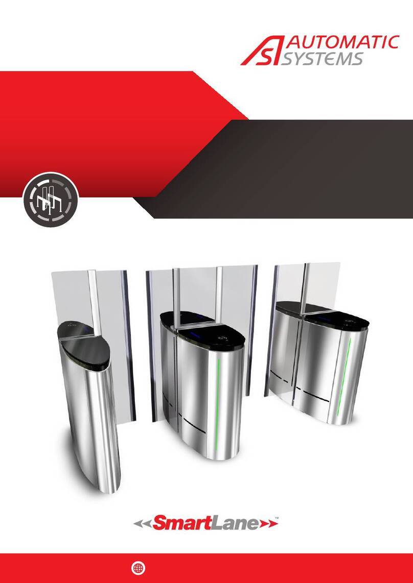
Automatic Systems SMARTLANE SL 90X User manual

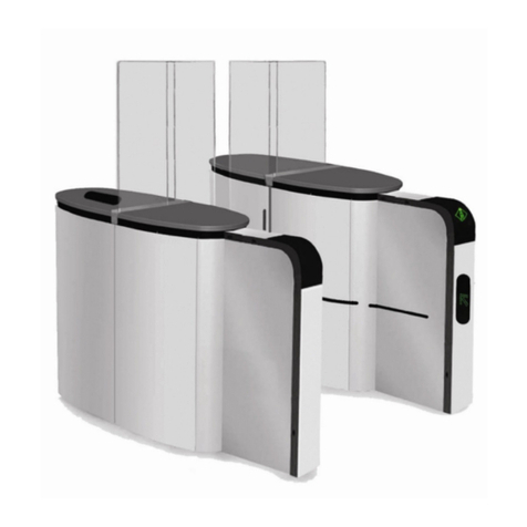
SMARTLANE
Technical Manual
NAM-SL 90X-91X-TM-02-EN-E
www.automatic-systems.com
SECURITY ENTRANCE LANES
SL 90X – SL 91X
TECHNICAL MANUAL
Rev E
INSTALLATION
SITE PREPARATION
USER
MAINTENANCE

SL 90X-91X
Technical Manual
NAM-SL 90X-91X-TM-02-EN-E
With a constant view to adopting the latest technological developments, Automatic Systems reserves the right to amend the above information at any time
.
p. 2/37
www.automatic-systems.com
Document revisions
Revision
Date
Written
by
Checked
by
Subject
C
2014-06-17
SOS
•Sect 17: Wiring diagram updated
D
2016-06-02
ALE
•Sect 17: Wiring diagram updated
E
2018-09-27
LBI
VBO
•Updated template

SL 90X-91X
Technical Manual
NAM-SL 90X-91X-TM-02-EN-E
With a constant view to adopting the latest technological developments, Automatic Systems reserves the right to amend the above information at any time
.
p. 3/37
www.automatic-systems.com
Table of contents
DOCUMENT REVISIONS.......................................................................................................................................................2
TABLE OF CONTENTS.........................................................................................................................................................3
1. SAFETY WARNINGS.......................................................................................................................................................4
1.1. User safety ...................................................................................................................................................................................................4
1.2. Technical staff safety ..................................................................................................................................................................................4
2. ABOUT THE MANUALS ...................................................................................................................................................6
2.1. Manual structure ..........................................................................................................................................................................................6
2.2. About this manual ........................................................................................................................................................................................6
3. PRODUCT AT A GLANCE .................................................................................................................................................7
4. DEFINITIONS ................................................................................................................................................................8
5. TYPES OF UNITS ...........................................................................................................................................................9
6. CONFIGURATIONS ....................................................................................................................................................... 10
6.1. Master/slave single configuration .............................................................................................................................................................10
6.2. Multiple lane configuration of the SL 90X or SL 91X lane............................................................................................................................ 11
6.2.1. Intermediate unit................................................................................................................................................................................................................11
6.2.2. Hybrid intermediate unit ....................................................................................................................................................................................................12
7. COMPONENTS............................................................................................................................................................. 13
7.1. External component ...................................................................................................................................................................................13
7.2. Internal components ..................................................................................................................................................................................14
7.2.1. Mechanical assembly.........................................................................................................................................................................................................15
7.2.2. Logic panels .......................................................................................................................................................................................................................16
7.2.3. Power supply panel ............................................................................................................................................................................................................17
8. CHECKLIST: REQUIRED TOOLS......................................................................................................................................18
9. CHECKLIST: SITE PREPARATION WORK ......................................................................................................................... 19
10. INSTRUCTIONS: RECEIVING THE UNIT.......................................................................................................................... 20
10.1. Step-by-step instructions at glance ....................................................................................................................................................... 20
10.2. Detailed instructions ...............................................................................................................................................................................20
11. INSTRUCTIONS: INSTALLING THE EQUIPMENT .............................................................................................................. 23
11.1. Step-by-step instructions at a glance.....................................................................................................................................................23
11.2. Detailed instructions ...............................................................................................................................................................................23
12. ELECTRICAL CONNECTIONS ....................................................................................................................................... 27
13. PRELIMINARY CONNECTIONS ..................................................................................................................................... 28
14. FIRE OR EMERGENCY EXIT......................................................................................................................................... 29
15. GROUND CABLE CONNECTIONS................................................................................................................................... 30
15.1. Ground cable connection diagram............................................................................................................................................................31
16. WIRING DIAGRAM ..................................................................................................................................................... 32
17. CHECKLIST: ELECTRICAL CONNECTIONS...................................................................................................................... 33
18. INSTRUCTIONS: FIRST START-UP ...............................................................................................................................34
19. TROUBLESHOOTING................................................................................................................................................... 35
19.1. Installation troubleshooting .................................................................................................................................................................... 35
19.2. Start-up troubleshooting .........................................................................................................................................................................35
SL 90X-91X
Technical Manual
NAM-SL 90X-91X-TM-02-EN-E
With a constant view to adopting the latest technological developments, Automatic Systems reserves the right to amend the above information at any time
.
p. 4/37
www.automatic-systems.com
1. SAFETY WARNINGS
IMPORTANT SAFETY INSTRUCTIONS
TO REDUCE THE RISK OF INJURY OR DEATH, READ AND FOLLOW ALL SAFETY INSTRUCTIONS
BEFORE INSTALLING, OPERATING OR SERVICING THE SECURITY ENTRANCE LANE. SAVE
THESE INSTRUCTIONS!
A number of safety precautions must be taken during the installation and use of a SmartLane
Security Entrance Lane.
1.1. USER SAFETY
•Do not cross the path of moving glass obstacles. The SmartLane Security Entrance Lane is
equipped with an unattended operation feature. The glass obstacles could move unexpectedly.
•DO NOT ENTER WHEN THE RED CROSS APPEARS. Only enter when you see the GREEN ARROW.
Employees working in the area must first be trained to use the automatic lanes. Failure to provide
such training to users can result in serious accidents or injuries.
•Due to risk of injury, unaccompanied children must not be allowed to access the lane.
•Children could place their hands on the obstacle before it is fully opened or has begun to open,
and their hands could be dragged along the obstacle and become pinched in the narrow gap of
the unit.
•Pets should not go through the lane.
1.2. TECHNICAL STAFF SAFETY
•Do not connect the equipment to a power source until instructed to do so. The SmartLane
Security Entrance Lane must be installed with permanent wiring in accordance with the local
code.
•All equipment operations must be performed by qualified personnel. All operations that are not
authorized or that are carried out by an unqualified technician shall automatically and legally void
the manufacturer’s warranty and liability.
•Ensure that the circuit breaker is turned off first before opening the housing of the SmartLane
Security Entrance Lane.
•Keep the circuit breaker turned off for any work that does not require the motor or the
programmable logic controller to be turned on.

SL 90X-91X
Technical Manual
NAM-SL 90X-91X-TM-02-EN-E
With a constant view to adopting the latest technological developments, Automatic Systems reserves the right to amend the above information at any time
.
p. 5/37
www.automatic-systems.com
•KEEP YOUR SMARTLANE SECURITY ENTRANCE LANE PROPERLY MAINTAINED as per manufacturer
recommendations.
•When servicing, keep the area around the Security Entrance Lane secured to avoid injuries from
moving parts.
•TO AVOID RISKS OF ELECTRICAL SHOCK, ensure that the Security Entrance Lane access panels are
locked at all times and only opened by trained personnel.
•All internal elements that may be powered up or that may move must be handled with care.
•Any modifications to the parameters must be performed by experienced and qualified personnel.
Automatic Systems is in no way responsible for any modifications made to the equipment. (Note:
the SmartLane Security Entrance Lane is factory configured in “minimal risk” mode for its users.)

SL 90X-91X
Technical Manual
NAM-SL 90X-91X-TM-02-EN-E
With a constant view to adopting the latest technological developments, Automatic Systems reserves the right to amend the above information at any time
.
p. 6/37
www.automatic-systems.com
2. About the Manuals
Thank you for choosing the SmartLane Security Entrance Lane. We are confident that your purchase
will fully meet your requirements.
2.1. MANUAL STRUCTURE
Different manuals are available for the SmartLane Security Entrance Lane. Please ensure that you
consult the appropriate manual.
Manual Intended for
Site Preparation Manual Site preparation contractor
Electrician
Installation Manual Installation contractor
Electrician
User Manual Security personnel
Managers
Maintenance Manual Qualified technicians
2.2. ABOUT THIS MANUAL
We strongly advise you to carefully read this manual, which will direct you through the necessary
installation process of the SmartLane Security Entrance Lane. In it, you will find step-by-step
instructions on how to proceed along with checklists of the required tools and the steps involved
for the installation.

SL 90X-91X
Technical Manual
NAM-SL 90X-91X-TM-02-EN-E
With a constant view to adopting the latest technological developments, Automatic Systems reserves the right to amend the above information at any time
.
p. 7/37
www.automatic-systems.com
3. Product at a Glance
Figure 1 Lane
Moving Glass obstacle
Extension
Fixed Glass obstacle
Unit
Passageway
Orientation
pictogram
Function
pictogram
Inner detection
photocells

SL 90X-91X
Technical Manual
NAM-SL 90X-91X-TM-02-EN-E
With a constant view to adopting the latest technological developments, Automatic Systems reserves the right to amend the above information at any time
.
p. 8/37
www.automatic-systems.com
4. Definitions
Balancing spring Helps the motor open and close the glass obstacle.
Extension Offered as an option; allows for an increased level of detection.
Fixed glass obstacle Fixed pane that blocks the area over the unit. When the moving glass
obstacles are higher than 39 in (990 mm), offered in matching height.
Function pictogram Indicates the procedure to follow.
Inductive position sensor Monitors the position of the glass obstacle and transmits this
information to the programmable logic controller (PLC).
Lane Composed of two (2) units and a passageway.
Locking mechanism Maintains the glass obstacle in an open position in the event of a
power cut or other emergency.
Moving glass obstacle Retractable pane that blocks the lane.
Orientation pictogram Indicates to the user whether the lane is free and the direction to
follow.
Passageway Corridor between two (2) units.
Release spring Unlocks the glass obstacle in the event of a power cut or other
emergency.
Unit Composed of the housing, detection photocells and motor glass
obstacles and (optional) extensions.

SL 90X-91X
Technical Manual
NAM-SL 90X-91X-TM-02-EN-E
With a constant view to adopting the latest technological developments, Automatic Systems reserves the right to amend the above information at any time
.
p. 9/37
www.automatic-systems.com
5. Types of Units
Each lane consists of two (2) units, each of which includes a retractable glass obstacle that blocks the
passageway.
There are six (6) different types of units.
The difference between the SL 90X and the SL 91X is the width of the passageway.
•The SL 90X has a 23-in passage width.
•The SL 91X has a 36-in passage width.
•The glass obstacles of an SL 91X lane are wider than those of an SL 90X to cover the wider
passageway. This means that the body of an SL 91X will be wider as well to accommodate the wider
glass obstacle.
Without extension
(SL 9x0)
Standard detection in both
directions of passage
1 extension
(SL 9x1)
Standard detection in one
direction of passage, enhanced
detection in the other
2 extension
(SL 9x2)
Enhanced detection in both
directions of passage
Narrow obstacle,
23-in width
(SL 90x)
Passage for users with normal
mobility
SL 900
SL 901
SL 902
Wide obstacle,
36-in width
(SL 91x)
Passage for users with reduced
mobility
SL 910
SL 911
SL 912

SL 90X-91X
Technical Manual
NAM-SL 90X-91X-TM-02-EN-E
With a constant view to adopting the latest technological developments, Automatic Systems reserves the right to amend the above information at any time
.
p. 10/37
www.automatic-systems.com
6. Configurations
Our product comes in single or multiple lane configurations.
In the configuration illustrations below:
•Direction A is the entry way (to access the secured side).
•Direction B is the exit way (to access the unsecured side).
6.1. MASTER/SLAVE SINGLE CONFIGURATION
Figure 2 Single lane configuration
Master Unit: Unit located on the user’s right side when the user is moving in direction A.
Slave Unit: Unit located on the user’s left side when the user is moving in direction A.
Exit
B
A
Entry
Slave Unit Master Unit

SL 90X-91X
Technical Manual
NAM-SL 90X-91X-TM-02-EN-E
With a constant view to adopting the latest technological developments, Automatic Systems reserves the right to amend the above information at any time
.
p. 11/37
www.automatic-systems.com
6.2. MULTIPLE LANE CONFIGURATION OF THE SL 90X OR SL 91X LANE
6.2.1. INTERMEDIATE UNIT
Figure 3 Multiple lane configuration
A multiple lane configuration is possible by placing one or more intermediate units between a Master
unit and a Slave unit.
The intermediate unit will serve as a Master unit for the lane to the left and as a Slave unit for the lane
to the right. The intermediate unit can create multiple lanes with the same width.
It cannot be used as a transition between an array composed of an SL 90X unit and an SL 91X unit.
Exit
B
Exit
B
A
Entry
A
Entry
Slave Unit Master Unit
Intermediate Unit

SL 90X-91X
Technical Manual
NAM-SL 90X-91X-TM-02-EN-E
With a constant view to adopting the latest technological developments, Automatic Systems reserves the right to amend the above information at any time
.
p. 12/37
www.automatic-systems.com
6.2.2. HYBRID INTERMEDIATE UNIT
Figure 4 Multiple lane configuration
An SL 91X lane can be installed next to an SL 90X. This configuration will require the use of an SL 91X
hybrid intermediate unit that houses both an SL 90X glass obstacle and an SL 91X glass obstacle to
create a transition between each lane type.
Left and right hybrid intermediate units are available.
•For a left hybrid intermediate unit, the SL 90X glass obstacle (narrower) will be on the left.
•For a right hybrid intermediate unit, the SL 90X glass obstacle (narrower) will be on the right.
Exit
B
Exit
B
A
Entry
A
Entry
Slave Unit Master Unit
Intermediate Unit
Left Hybrid

SL 90X-91X
Technical Manual
NAM-SL 90X-91X-TM-02-EN-E
With a constant view to adopting the latest technological developments, Automatic Systems reserves the right to amend the above information at any time
.
p. 13/37
www.automatic-systems.com
7. Components
7.1. EXTERNAL COMPONENT
Figure 5 External components
1. Fixed glass obstacles [moving glass obstacles of matching height only offered when glass
obstacles are higher than 39 in (990 mm)]
2. Moving glass obstacles
3. Top cover
4. Function pictogram on optional extension – suggested location for card reader system
5. Detection photocells
6. Orientation pictogram on optional extension – possible location for additional card reader (special
faceplate required)
7. Function pictogram without optional extension – card reader system location
8. Orientation pictogram without optional extension
7
8
5
3
4
6
1
2

SL 90X-91X
Technical Manual
NAM-SL 90X-91X-TM-02-EN-E
With a constant view to adopting the latest technological developments, Automatic Systems reserves the right to amend the above information at any time
.
p. 14/37
www.automatic-systems.com
7.2. INTERNAL COMPONENTS
Figure 6 Internal components
1. Mechanical assembly (one per moving glass obstacle)
2. Gear motor (one per moving glass obstacle)
3. Locking mechanism (one per moving glass obstacle
4. Inductive position sensor (one per moving glass obstacle)
5. Electrical panel
5
1
2
3
4
5

SL 90X-91X
Technical Manual
NAM-SL 90X-91X-TM-02-EN-E
With a constant view to adopting the latest technological developments, Automatic Systems reserves the right to amend the above information at any time
.
p. 15/37
www.automatic-systems.com
7.2.1. MECHANICAL ASSEMBLY
Figure 7 Mechanical assembly
1. Higher shaft
2. Balancing spring
3. Plinth
4. Locking mechanism
5. Inductive position sensor
6. Crankshaft
7. Release spring
8. Lower rod
9. Lower shaft
10. Higher rod

SL 90X-91X
Technical Manual
NAM-SL 90X-91X-TM-02-EN-E
With a constant view to adopting the latest technological developments, Automatic Systems reserves the right to amend the above information at any time
.
p. 16/37
www.automatic-systems.com
7.2.2. LOGIC PANELS
Figure 8 PLC panel
Left: Master unit (right and intermediate unit)
Right: Left unit panel
1. AS1145 analog signal to CAN interface
2. TB5: Terminal block of the Slave unit (Slave to Master) (intermediate and left units only)
3. Buzzer
4. TB4: Terminal block of the Slave unit (Master to Slave) (intermediate and right units only)
5. TB3: Terminal block of the PLC
6. AS1162 CAN interface
7. Fuse
8. Programmable logic controller (PLC): Modicon M340

SL 90X-91X
Technical Manual
NAM-SL 90X-91X-TM-02-EN-E
With a constant view to adopting the latest technological developments, Automatic Systems reserves the right to amend the above information at any time
.
p. 17/37
www.automatic-systems.com
7.2.3. POWER SUPPLY PANEL
9. Speed controller
10. TB2: 24-VDC terminal block
•Locking mechanism power supply
•Emergency contactor connection
11. 120-V to 24-V transformer
12. Main circuit breaker
13. TB1: 120-VAC terminal block
14. CONT1: Emergency contactor
15. Secondary circuit breaker
16. JB1: 120-V main power supply
17. JB2: 240-V power supply (Slave motor connection)
18. 120-V to 240-V transformer
19. CB3: Slave motor breaker
20. CB4: Master motor breaker
21. AS1145 analog signal to CAN interface (also used for the speed controller)
Figure 9 Power supply panel

SL 90X-91X
Technical Manual
NAM-SL 90X-91X-TM-02-EN-E
With a constant view to adopting the latest technological developments, Automatic Systems reserves the right to amend the above information at any time
.
p. 18/37
www.automatic-systems.com
8. Checklist: Required Tools
The following equipment is required for the site preparation work:
Implementation drawings
•These drawings are essential for the installation of the Security Entrance Lane
•They are provided with the contract agreement and are specific to each installation
Crowbar
Dolly
Fish tape
Hammer
Level
Sharp knife
Tape measure
Terminal block screwdriver
Vernier caliper
Wire stripper
Wrench set

SL 90X-91X
Technical Manual
NAM-SL 90X-91X-TM-02-EN-E
With a constant view to adopting the latest technological developments, Automatic Systems reserves the right to amend the above information at any time
.
p. 19/37
www.automatic-systems.com
9. Checklist: Site Preparation Work
Check that the following has been done prior to installing the Security Entrance
Lane.
Floor level and quality has been corrected
Holes have been drilled
Holes have been cleaned
Conduits and cables have been installed:
Conduit 1 installed
120 VAC single phase, 60 Hz power cable
Conduit 2 installed
Control cables for the access control reader and lane door output
Conduit 3 installed
Master/Slave Motor: High voltage interconnection cable
Conduit 4 installed
Master/Slave: Low voltage interconnection cable
Internal CAN Network cable
Network cable for remote control lane (optional)

SL 90X-91X
Technical Manual
NAM-SL 90X-91X-TM-02-EN-E
With a constant view to adopting the latest technological developments, Automatic Systems reserves the right to amend the above information at any time
.
p. 20/37
www.automatic-systems.com
10. Instructions: Receiving the Unit
10.1. STEP-BY-STEP INSTRUCTIONS AT GLANCE
1. Inspect the package
2. Bring the lane on site
3. Remove the nails
4. Cut the polystrap bands
5. Remove the wrapping
6. Remove the side panel
7. Unscrew the anchor bolts
8. Move the unit
10.2. DETAILED INSTRUCTIONS
1. Inspect the package
Carefully inspect your crate for exterior damage.
The lane is delivered in a crate. Its base is fixed to a wood pallet via anchor bolts. Foam panels are
placed between the glass obstacles to avoid damage during transport.
Immediately notify your insurance company or your distributor if any damage occurs during transport.
Other manuals for SMARTLANE SL 90X
1
This manual suits for next models
1
Table of contents
Other Automatic Systems Turnstile manuals

Automatic Systems
Automatic Systems TriLane TL2 User manual

Automatic Systems
Automatic Systems TriLane TL1 User manual

Automatic Systems
Automatic Systems SMARTLANE SL 90 Series User manual

Automatic Systems
Automatic Systems SmartLane User manual

Automatic Systems
Automatic Systems SL930 User manual

Automatic Systems
Automatic Systems TriLane TL Series User manual

Automatic Systems
Automatic Systems TR450 User manual

Automatic Systems
Automatic Systems TR491 User manual