10
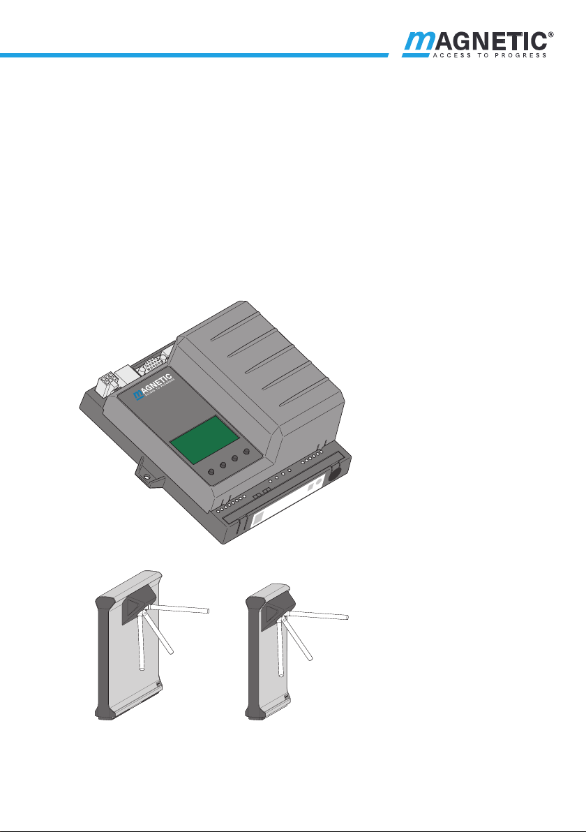
Control unit MGC mTripod
Digital inputs, digital outputs and relay outputs
2 Digital inputs, digital outputs and relay outputs
WARNING
Improper wiring and parameterisation of the control unit!
Improper wiring and parameterisation of the control unit can
lead to undesired functions and thus to injuries.
› Only MHTM™ FlowMotion® service experts, skilled technicians
or electrical safety experts may wire up and parameterise the
control unit.
› The electrical connection of the signal transmitters to the IN1
to IN8 inputs must fit the parameterisation.
Parameterisation: äPage 18, chapter 3.
2.1 Digital inputs
Definition of "Left" and "Right": äPage 62, chapter 7.1.
By parameterising the inputs, you assign certain functions to the inputs. For
example, if you parameterise the "Illumination off" function for input IN7,
switch the illumination on and off via this input.
If the function is marked with "|", the input is inverted (closed-circuit
principle). äPage 54, chapter 6.3.3.
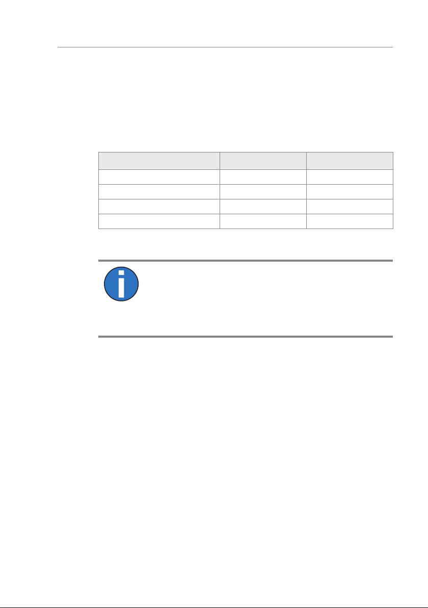
The following functions are assigned to the inputs as default settings:
Clamp Description Input function
IN1 Digital input 1 | Emergency open
IN2 Digital input 2 Open from left
IN3 Digital input 3 Open from right
IN4 Digital input 4 Random check function
IN5 Digital input 5 Confirm warnings
IN6 Digital input 6 Inhibit opening
IN7 Digital input 7 Illumination off
IN8 Digital input 8 | End switch drop arm
Table 3: Factory setting "Digital inputs"