Metra Electronics Tripod User manual

Tripod Turnstile Technical Manual

Page 2
Tripod Turnstile Technical Manual
Table of contents
Tripod Turnstile Technical Manual.......................................................................................................... 3
Product description............................................................................................................................. 3
Basic parts ........................................................................................................................................... 4
Wristband Capturer (optional) ....................................................................................................... 4
Antenna with Reader (optional) ..................................................................................................... 4
On the outside ................................................................................................................................ 5
On the inside................................................................................................................................... 5
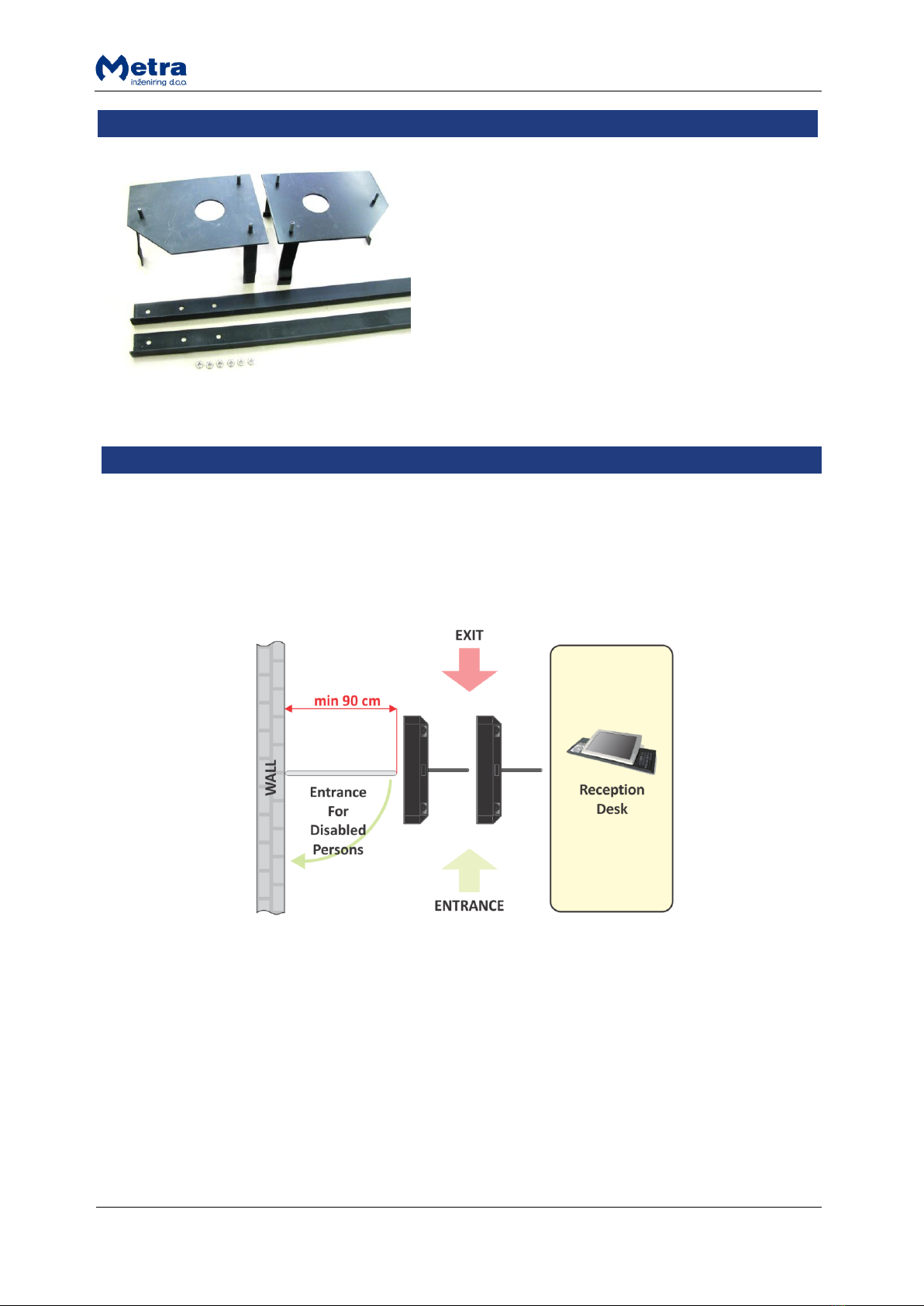
Mounting set (optional)...................................................................................................................... 6
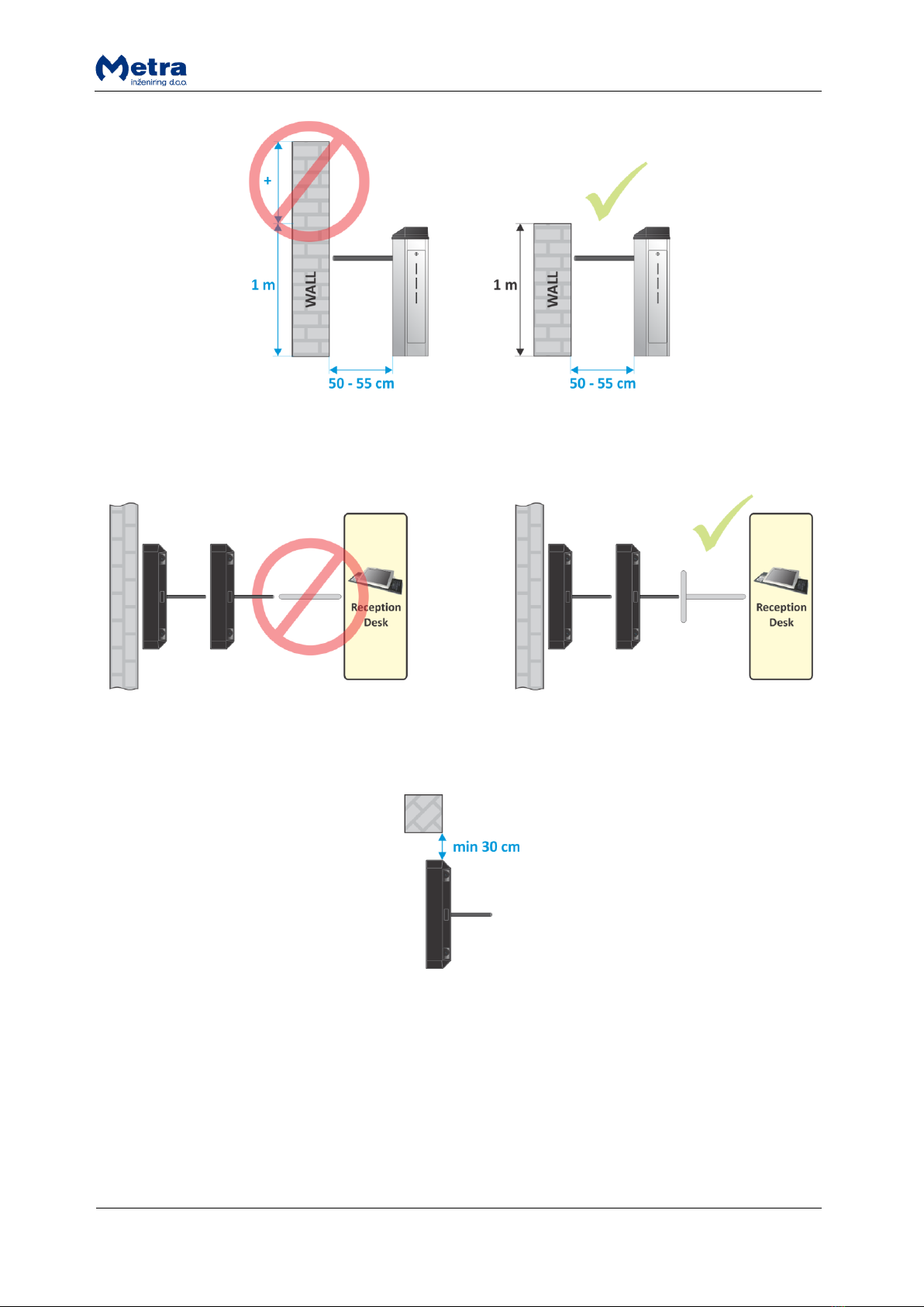
Choosing location for installation ....................................................................................................... 6
Wires installation ................................................................................................................................ 8
Anchor position (orientation) ......................................................................................................... 8
Preparation of wiring...................................................................................................................... 8
Wiring ............................................................................................................................................. 8
Anchor installation.............................................................................................................................. 9
Other installation options ................................................................................................................. 11
Opening cover................................................................................................................................... 11
Connections ...................................................................................................................................... 12
Top................................................................................................................................................ 12
Bottom.......................................................................................................................................... 13
Power supply connection ............................................................................................................. 14
Network connection ..................................................................................................................... 15
DIP switch settings ............................................................................................................................ 16
Operating mode and Network address ........................................................................................ 17
Power-ON.......................................................................................................................................... 17
Spare Fuse..................................................................................................................................... 18
Safety features .................................................................................................................................. 19
Free passage ................................................................................................................................. 19
Special braking fuses (optional).................................................................................................... 19
Barrier calibration ............................................................................................................................. 19
Maintenance ..................................................................................................................................... 20
Cleaning............................................................................................................................................. 20
Technical data ................................................................................................................................... 20
Appendix ........................................................................................................................................... 20

Page 3
Tripod Turnstile Technical Manual
Manufacturer:
Metra inženiring d.o.o.
IOC Trzin
Špruha 19
SI-1236 Trzin, Slovenia
phone:
fax:
web:
+386 1 56 10 740
+386 1 56 10 744
www.metra.si
System:
Metra Access Control
Product Group:
Tripod Turnstile
Types:
TTIS(CC) (ISO Reader)
TTISIS(CC) (ISO Reader on both sides)
TTRIS(CC) (ISO Wristband Capturer)
TTRISIS(CC) (ISO Wristband Capturer and Reader)
TTRCIS(CC) (ISO Card Capturer)
TTRCISIS(CC) (ISO Card Capturer and Reader)
TTMF(CC) (Mifare Reader)
TTMFMF(CC) (Mifare Reader on both sides)
TTRMF(CC) (Mifare Wristband Capturer)
TTRMFMF(CC) (Mifare Wristband Capturer and Reader)
TTRCMF(CC) (Mifare Card Capturer)
TTRCMFMF(CC) (Mifare Card Capturer and Reader)
Year of Construction:
1995 - 2011
Declaration of Conformity:
The Metra Access Control products have been developed, designed and
manufactured in accordance with the EU directive for
Electromagnetic Compatibility (2004/108/EC).
Tripod Turnstile Technical Manual [rev.1-240812]
2012 Metra inženiring d.o.o.
All Rights reserved.
No part of this manual may be reproduced in any form or by any means without prior written permission of Metra inženiring d.o.o.
The contents of this manual are subject to change without notice. All efforts have been made to ensure the accuracy of the contents of this manual, however, should any errors be
detected, Metra inženiring would greatly appreciate being informed of them.
Metra inženiring d.o.o. can assume no responsibility for any errors in this manual.
Product description
Tripod Turnstile is a complete, compact access control
point. It combines motorized rotating barrier with
RFID readers to control entrance and exit. Because
everything is integrated into a single housing, it
reduces required space for passage.
For exit control a patented Metra Wristband Capturer
can be integrated to allow Ticket retain feature. The
storage drawer for captured wristbands and/or cards
is incorporated in the housing that is a combination of
stainless steel body in matte finish and synthetic or
carbon fibre reinforced resin cover. Fluent pedestrian
passage is achieved by combination of visual LED and
audio signalization and proximity sensors triggering
motor driven rotating barrier. The drive was designed
and proven to prevent any injury but is tough enough
to withstand misuse at the same time. The barriers
are free rotating if the mains power is down and can
also be equipped with a special breaking fuse
(mechanical) for the case of panic.

Page 4
Tripod Turnstile Technical Manual
Tripod Turnstile is connected to Metra NET Network. When RFID Ticket is presented, access rights
are checked in the Metra software check engines. If valid, the unit drives its rotating barrier in
desired direction.
Passage on Tripod Turnstile for a particular ticket can also be externally controlled by 3rd party SW via
TCP/IP software interface. Metra software is used for event analyses and definition of operating
parameters.
Ticket retain feature allows re-using of various tickets. For that
innovative feature Metra has developed patented in 1998 contact-
less Wristband Capturer (WBC) together with contactless RFID
Wristband. The Wristband Capturer grants exit signal only when the
ticket is successfully erased and retained. This dramatically cuts
costs of the system operation and the chance of fraud. A ticket will
be retained under following conditions:
Retain request written on it/assigned to it.
It is presented to the retaining device.
Basic parts
Wristband Capturer (optional)
Wristband Capturer is a retaining module for Metra RFID
wristbands. It is integrated in different Metra products such
as Tripod Turnstile and Turnstile Access Terminal.
Consult the “Wristband Capturer – Technical Manual” for
more details.
Antenna with Reader (optional)

Page 5
Tripod Turnstile Technical Manual
On the outside
#
description
#
description
1
Cover / Antenna / Wristband Capturer
4
Proximity sensors
2
Signalization panel
5
Barrier
3
Ticket container/Cover
6
Wristband capacity control windows
On the inside
There are four main components inside the Tripod Turnstile. Those are: Master PCB, Slave PCB,
Turnstile Drive Mechanism II (Mechanism and Motor Driver PCB) and Wristband Capturer (optional).
Consult the “Turnstile Drive Mechanism II –Technical Manual” and “Wristband Capturer – Technical
Manual” for more details about those two components.
#
description
#
description
1
Buckle
4
Connection board
2
Turnstile Drive Mechanism II
5
Slave electronics board
3
Master electronics board
6
Optical proximity sensors

Page 6
Tripod Turnstile Technical Manual
Mounting set (optional)
Beforehand provided anchors (if the anchors are going
to be built-in the pave)
2 x built-in anchors (left and right)
2 x spacers for anchors
6 x M8 nuts
Choosing location for installation
Placement of device is chosen regarding the project plan. Take into consideration the following
advices regarding the orientation and location of Tripod Turnstile(s):
Receptionist should have good overview to the front side of the device(s).
The best position regarding reception desk is that receptionist has access to incoming and leaving
guests (extra payment on leaving).
When an entrance for disabled persons is mounted, it needs to be at least 90 centimetres wide.
If the device stands alone, you need to mount a barrier at 50 to 55 centimetres from edges or find
already fixed barrier (wall, column, etc.). The barrier should be of the same high as the device,
which is 1 metre.

Page 7
Tripod Turnstile Technical Manual
If there is more than one device in a row, only the first Turnstile needs a fixed barrier. Other
devices are using next device as a barrier.
On the left and right side of the device there need to be at least 30 cm of free space to take out
the storage with captured tickets.
Devices should also be protected from direct sun and rain. The best place for this purpose is inside
the building or under projecting roof.
At night or when device is out of (stuff) control, it is better to have some kind of protection
against vandalism (wire fence, door, etc.).
When the device is installed directly on concrete foundation, durable carpet should be provided.
Fixing the Turnstile is done in two levels which also enable micro settings and out of season de-
montage.
When you do concrete, we advise to do larger surface (plate) for better solidity of installation.

Page 8
Tripod Turnstile Technical Manual
Wires installation
NOTE
Before the installation of the device the built-in anchors and wire installations must be checked.
Anchor position (orientation)
Check the position of both built-in anchors and their height and position according to the pavement.
Clean the surface of the built-in anchors.
Preparation of wiring
Put a ribbed plastic hose 30 millimetres for installation
of cables through the anchor on the entrance side. If
installation requires (for example: external Enter/Exit
buttons are on different location than Power supply and
Metra Net Network), more than one ribbed plastic hose
can be put in. Each installed cable should be at least 1.5
metre long from the ground.
Wiring
NOTE
Cables are always installed through the leg on the ENTRANCE SIDE of the Tripod Turnstile.

Page 9
Tripod Turnstile Technical Manual
#
connection
mandatory / optional
wire / no. of conductors
1
24 VDC
Mandatory
1.5 mm2soft wire PPL / 2
2
Metra NET Network
Mandatory
Twisted pair or UTP cable / 2 (8 if UTP)
3
External ENTER / EXIT
Buttons
Optional
0.75 mm² soft wire PPL / 4
Anchor installation
See chapter “Mounting set (optional)“ for required mounting elements.
STEP 1: Fix iron anchor spacers to the anchors with
supplied M8 nuts.
STEP 2: “Cut” sides of the anchor's (top view) should be
placed at the Turnstile's passage side.

Page 10
Tripod Turnstile Technical Manual
STEP 3: Anchors are put onto the place where the tripod
barrier device will stand. Be sure that anchors are
balanced in both horizontal directions. The concrete is
applied according to the final foundation (pave).
NOTE
Setting the 0/0 position: It is demanded that the anchor
spacers are placed onto the final foundation of the
existing level - the upper surface of both anchors is on
the same level as ceramics, marble, final foundation, etc.
When the concrete is dry, the anchor spacers are
removed and can be used again.
STEP 4: Attach the Tripod Turnstile on the anchors and
fix it with 6 x M8 nuts. Use M8 washers with external
diameter at least 24 millimetres or bigger. Washers are
not included with the anchors and must be bought
separately or they are provided by Metra when installing
the Tripod Turnstile. There are also rubber pads available
if anchors are slightly out of level and they are also used
for water insulation if needed. Contact Metra for more
details.
STEP 5: Final position of devices should look like these.

Page 11
Tripod Turnstile Technical Manual
Other installation options
Alternative mounting options are also possible.
If installing Tripod Turnstile indoors into a solid
pavement, it can be mounted using wall plugs, anchor
bolts, anchor screws, and even special glues. However,
the underground wiring needs to be done before the
installation of Tripod Turnstile. Method should be chosen
depending on the pave type.
NOTE
Drilling holes in pavement is not advised in the following cases:
Non-solid pavement.
Floor heating.
Other floor installations.
NOTE
Wiring scheme remains the same for all kinds of installations.
Opening cover
STEP 1: Unlock and remove the ticket container on one
side and the door on the other side of the Tripod
Turnstile.
STEP 2: There is a buckle holding the Cover in place on
each side. Unbuckle them.
STEP 3: Lift the Cover. If needed disconnect the
signalization panel, Reader (if present) and Wristband
Capturer (if present). Mark cables exact position.

Page 12
Tripod Turnstile Technical Manual
Connections
Top
#
description
#
description
1
Semaphore Slave
8
Not Used
2
Semaphore Master
9
Power & Metra NET Network
3
Wristband Capturer
10
Antenna Signalization LED
4
Reader Master (optional)
11
Metra NET Network
5
Reader Slave (optional)
12
Metra NET Network
6
Not Used
13
Not Used
7
Not Used

Page 13
Tripod Turnstile Technical Manual
Bottom
#
description
#
description
1
Pushbutton input –Master
9
Not Used
2
Turnstile Drive Mechanism II communication connection
10
Not Used
3
Turnstile Drive Mechanism II power connection
11
Not Used
4
Not Used
12
Not Used
5
Pushbutton input –Slave
13
Not Used
6
Not Used
14
BDM Loader
7
Not Used
15
Not Used
8
BDM Loader
16
Not Used

Page 14
Tripod Turnstile Technical Manual
1, 4
Pushbutton input –Master/Slave
Power supply connection
Regulated 24 VDC power supply is required for proper operation. Consult the Technical Specifications
section of this document for current consumption.
Connect 24V DC regulated power supply to designated
terminals. The terminals are marked as “+24”for positive
connection and “gnd”for ground connection.
WARNING
Mind the polarity! Wrong polarity could result in
irreparable damage to the device.
Respect power requirements data! Using unsuitable
power supply could result in damage to the power
supply and to the device.

Page 15
Tripod Turnstile Technical Manual
NOTE
Make sure that Power/Network cable is connected to the distribution board.
Network connection
The network connection provides for operational functionality of the Tripod Turnstile. Different
devices in parallel can be connected to the Network Controller by a single unshielded twisted pair
(UTP) cable. Total length of the twisted pair cable is limited to 1 km. One Network Line Terminator
must be connected at the far end of the network cable.
OPTION I:
Connect the twisted pair network cable to designated
terminals. The terminals are marked as “C_L”for network
low signal and “C_H”for network high signal.
OPTION II:
Connect the twisted pair network cable with RJ-45
connector to one of RJ-45 connectors on the “connection
board”.
NOTE FOR OPTION II
There are 2 equivalent UTP connectors for Metra NET Network connection. One can be used as
“trunk line IN” and the other as “trunk line OUT”connector. Take into consideration that if you
disconnect one of the UTP cables (in or out), you also cut off the “trunk line” and devices after this
device will be disconnected from the Metra NET Network. Therefore this type of connection is
recommended only if you use Master and Slave Network Controllers TCP/IP, each on one side of the
“trunk line”.
NOTE
Mind the polarity of the network connection!
Always connect the line terminator at the far end of the network cable!

Page 16
Tripod Turnstile Technical Manual
DIP switch settings
#
description
1
Parameters request button - Slave
2
Network Address DIP switch - Slave
3
Parameters request button - Master
4
Operating Mode/Network Address DIP switch - Master
By changing the Network Address DIP Switch ( and ) pins positions, different network
addresses can be set. To change between different pins positions, use a small flat headed
screwdriver or similar object to push DIP switch pins to desired position.
After each settings change or after device’s first installation power off and back on the device (for the
new settings to take effect) and obtain operating parameters if the device is connected to Metra NET
Network controlled by Metra Network Controller and Metra SW.
Operating parameters are obtained through the Metra NET Network. The server must be set up and
running for that purpose. To obtain operating parameters, press the PARAMETERS REQUEST buttons
( and ) on Master and on Slave electronics board.

Page 17
Tripod Turnstile Technical Manual
Operating mode and Network address
After installation is complete, the device’s network addresses must be set by changing the Network
Address DIP Switch ( and ) pins positions.
NOTE
Each Metra device must have different address setting.
Switches #1 and #2 are reserved for future use and must be set to OFF position (switch down).
Set switch #3 on Master electronics board according devices hardware configuration:
OFF (switch down) indicates no Wristband Capturer is connected.
ON (switch up) indicates the Wristband Capturer is connected.
Set switch #3 on Slave electronics board to OFF position (switch down).
Look up the code for desired Metra NET Network address in the coding table. Set switches #4
through #8 to indicated positions, where:
0 indicates the corresponding switch is in OFF position (switch down).
1 indicates the corresponding switch is in ON position (switch up).
Coding table:
switch positions
Master
address
Slave
address
switch positions
Master
address
Slave
address
4
5
6
7
8
4
5
6
7
8
0
0
0
0
0
300
332
1
0
0
0
0
316
348
0
0
0
0
1
301
333
1
0
0
0
1
317
349
0
0
0
1
0
302
334
1
0
0
1
0
318
350
0
0
0
1
1
303
335
1
0
0
1
1
319
351
0
0
1
0
0
304
336
1
0
1
0
0
320
352
0
0
1
0
1
305
337
1
0
1
0
1
321
353
0
0
1
1
0
306
338
1
0
1
1
0
322
354
0
0
1
1
1
307
339
1
0
1
1
1
323
355
0
1
0
0
0
308
340
1
1
0
0
0
324
356
0
1
0
0
1
309
341
1
1
0
0
1
325
357
0
1
0
1
0
310
342
1
1
0
1
0
326
358
0
1
0
1
1
311
343
1
1
0
1
1
327
359
0
1
1
0
0
312
344
1
1
1
0
0
328
360
0
1
1
0
1
313
345
1
1
1
0
1
329
361
0
1
1
1
0
314
346
1
1
1
1
0
330
362
0
1
1
1
1
315
347
1
1
1
1
1
331
363
Power-ON
To power button is situated on the connection board.

Page 18
Tripod Turnstile Technical Manual
#
description
1
F3.15 A 5mm x 20mm fast fuse
2
Power ON/OFF button
Spare Fuse
Tripod Turnstile uses one F3.15 A 5mm x 20mm fast fuse. Spare one is located on the back of the
connection board.

Page 19
Tripod Turnstile Technical Manual
Safety features
Different safety features are available on the Tripod Turnstile
Free passage
If mains power is down the barrier is rotating freely in both directions.
Special braking fuses (optional)
If even higher safety is required, barriers can be equipped with special braking fuses that brake if
high force is applied to the barriers (people leaning on the barrier, mass of peoples push against the
barrier). Barrier can be easily and quickly reinstalled using a new braking fuse.
Barrier calibration
Each barrier (when in top position) should be
perpendicular to the metal housing. Consult “Turnstile
Drive Mechanism II –Technical Manual” for barrier
calibration procedure.

Page 20
Tripod Turnstile Technical Manual
Maintenance
The maintenance service should perform a check on the device:
At least once a year.
When it has not been in use for a long time.
When functional errors appear.
The device should be protected from mechanical damages, such as bending barriers and similar,
which usually result from improper use like jumping over the barrier or climbing over the bars. Such
abuse can be detected by proximity sensors and will be signalized by a beep sound, if enabled in
device parameters.
Cleaning
The device housing should be cleaned using only detergents, suitable for rust resistant metals. The
resin cover should be cleaned using soft cloth and dedicated cleaners for plastic surfaces e.g. car
dashboard cleaning agents. Do not use any aggressive or abrasive agents or solvents as they might
cause permanent damage to the device surface.
Technical data
Operating voltage
24V DC regulated; (22 –30V DC tolerated)
Current consumption
2 A
Fuse
Fast Fuse 3.15 A
Operating temperature range
0 to +50 °C
Passage corridor width
50 cm
Barrier height
78.5 cm
Passage frequency
10-12 persons / min
Audio signal
integrated piezoelectric beeper
Visual signalization
LED semaphores
Network type
Metra NET Network
Barrier type
Motorized, absolute position magnetic sensor
Dimensions in mm (w/h/l)
740/980/1220
Appendix
1
Physical dimensions
2
Typical Installation
This manual suits for next models
12
Table of contents
Popular Turnstile manuals by other brands

Record
Record Speedgate slide user manual

EMIT
EMIT SmartLog Pro SE Installation, operation and maintenance

Alvarado
Alvarado SLT INSTRUCTIONS AND MAINTENANCE GUIDE

Tiso
Tiso ASTM F2656 M50 Installation and operation manual

HIK VISION
HIK VISION DS-K3B601-L Series quick start guide

LBA GROUP
LBA GROUP LBAT10 operating instructions