Page 10 of 16 / IM 1171-3
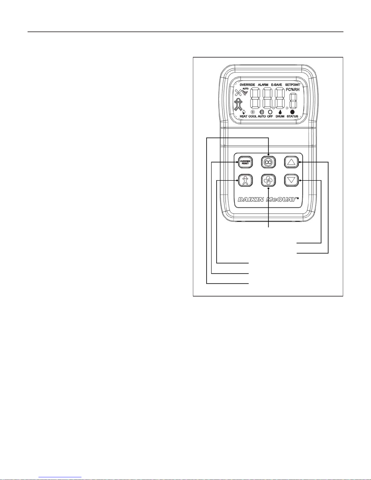
Front Panel Button Operation
System Mode Indication (FCU Only)
“Heat/Cool/Auto/Off”
The “Heat/Cool/Auto/Off” Mode Indicators on the bottom
of the display show the mode status of the sensor and are
changed by pushing the System Mode button.
• “Cool” on the display means the unit will only provide
cooling.
• “Heat” on the display means the unit will only provide
heating.
• “Auto” on the display means the unit switches
automatically to provide cooling or heating.
• “Off” on the display means the unit will not provide
cooling, heating or fan operation.
There should always be one indicator “On” unless the sensor
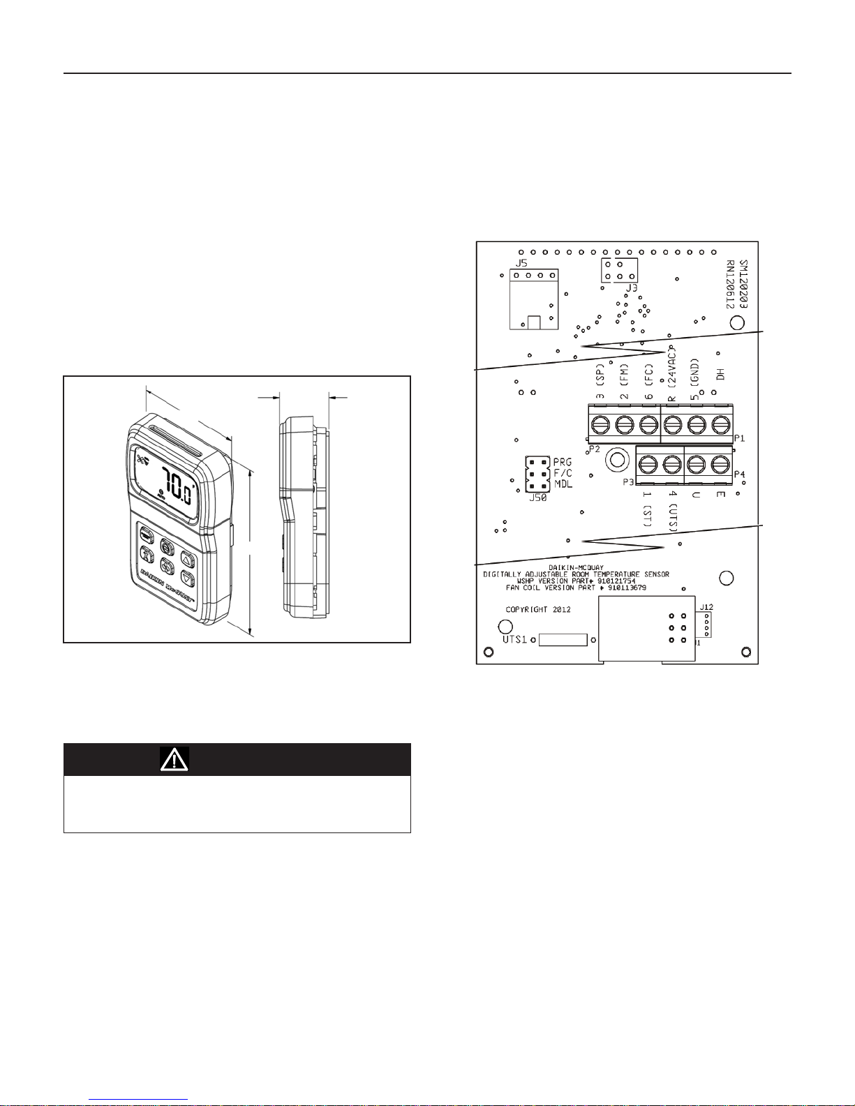
has no power or has a problem. The System ModeAnalog Out-
put voltage on Term. 2 will change based on the system mode.
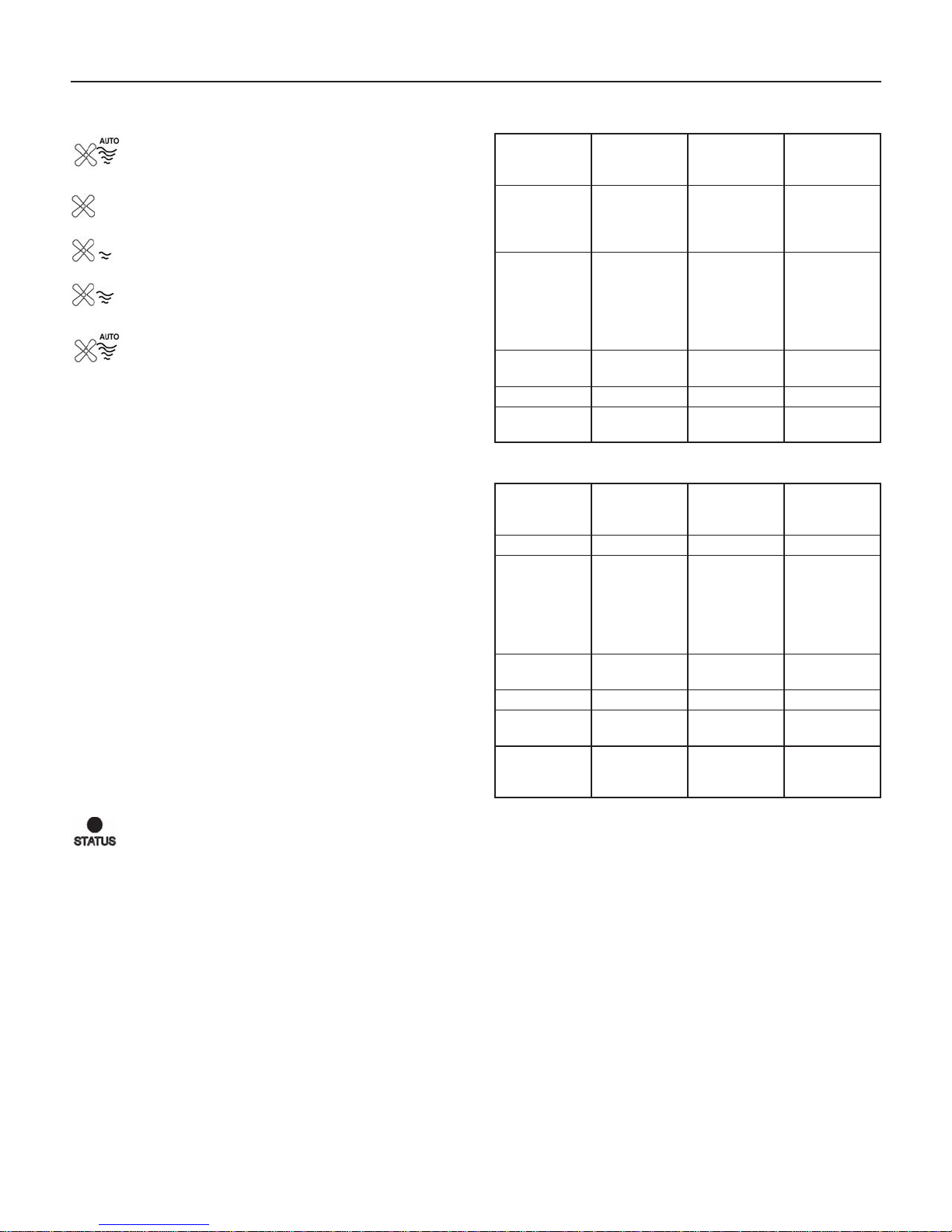
Fan Speed Indication (FCU Only)
“Auto/High/Medium/Low”
The Fan Speed Indicators on the display show the fan speed
status (Auto/High/Medium/Low) and are changed by pushing
the Fan Mode button.
“Fan & 4 Wavy Lines & Auto” - the fan stages up
or down automatically depending on the demand
for cooling or heating.
“Fan & 4 Wavy Lines” - the fan runs continuously
at high speed regardless of the system mode setting
of Heat/Cool/Auto.
“Fan & 3 Wavy Lines” - the fan runs continuously
at medium speed regardless of the system mode
setting of Heat/Cool/Auto.
“Fan & 2 Wavy Lines” - the fan runs continuously
at low speed regardless of the system mode setting
of Heat/Cool/Auto.
“Fan & No Wavy Lines” - Indicates the fan is Off.
There should always be one indicator “On” unless the sensor
has no power or has a problem. The Fan SpeedAnalog Out-
put voltage on Terminal 6 will change based on the fan speed
selection.
System Mode Indication (WSHP Only)
“Heat/Cool/Auto/Off/Dhum”
The “Heat/Cool/Auto/Off/Dhum” Mode Indicators on the
display show the mode status of the sensor and are changed
by pushing the System Mode button.
• “Cool” on the display means unit will only provide
cooling.
• “Heat” on the display means the unit will only provide
heating.
• “Auto” on the display means the unit can switch
automatically to provide cooling or heating or
dehumidication.
• “Off” on the display means the unit will not provide
cooling, heating, dehumidication or fan operation (“E”
terminal goes Low).
• “Dhum” on the display means that only dehumidication
will operate.
There should always be one indicator “On” unless the sensor
has no power or has a problem. The System ModeAnalog
Output voltage on Terminal 2 will change based on the sys-
tem mode selection.
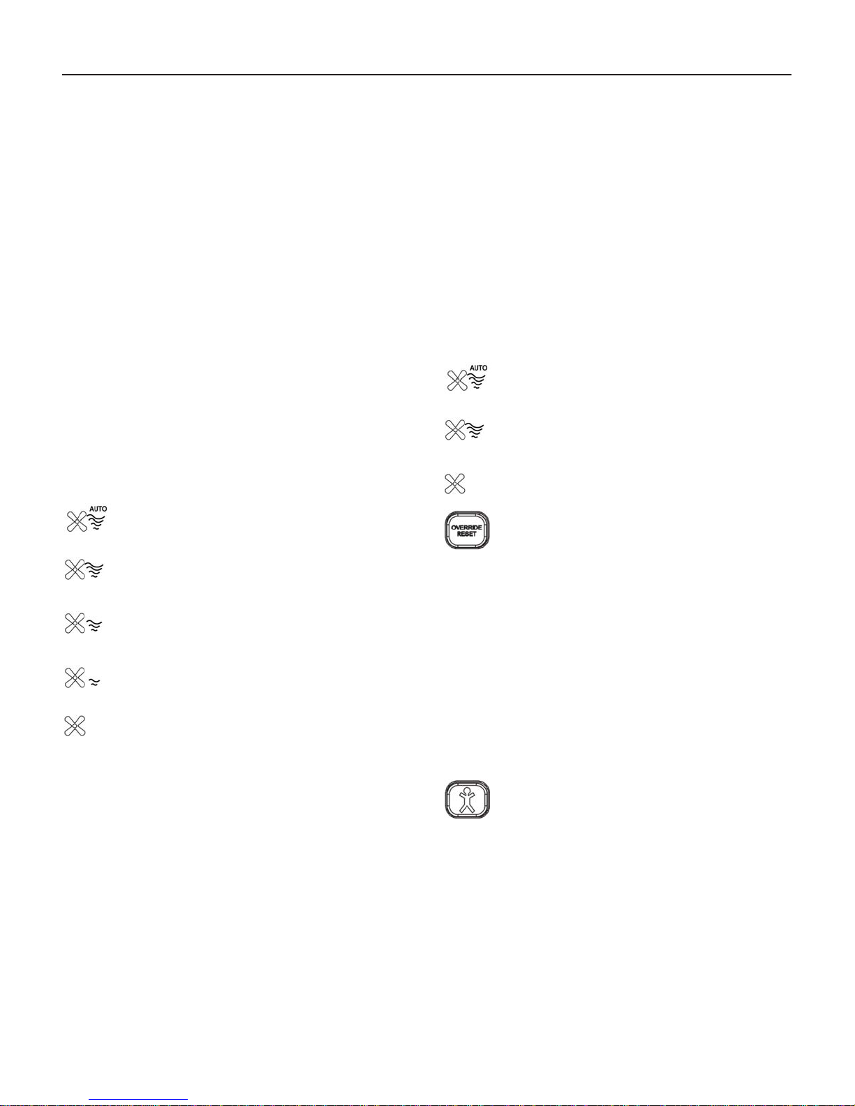
Fan Indication (WSHP Only)
“Auto/On”
The Fan Indicators on the left side of the display show the fan
status (Auto/On) of the sensor and are changed by pushing
the Fan Mode button.
“Fan & 4 Wavy Lines & Auto” - the fan runs on
a call for cooling, heating or Dhum. Otherwise the
fan is off.
“Fan & 4 Wavy Lines” - the fan is running
continuously regardless of the heating, cooling or
Dhum demand.
“Fan & No Wavy Lines” - the fan is Off when the
system mode is “Off”.
Override/Reset Button (Timed
Override & Alarm Reset):
When the “Override/Reset” Button is pressed, the thermis-
tor sensor is shorted. If held for more than 3 seconds but less
than 11 seconds, it puts the controller into a timed Occupied
Override (the time is set by the controller). If the unit is in
alarm, then holding the “Override/Reset” Button for more than
11 seconds will clear all alarms in the controller but only if the
cause of the alarm has already returned to its non-alarm condi-
tion. Some alarms will not reset from the digital room sensor.
In this case, power to the unit must be cycled off for 5 sec-
onds to clear the alarm. Continuously resetting alarms from
the room sensor could damage the controller. Please call a
service technician when repeated alarm resets are required to
keep the unit operational.
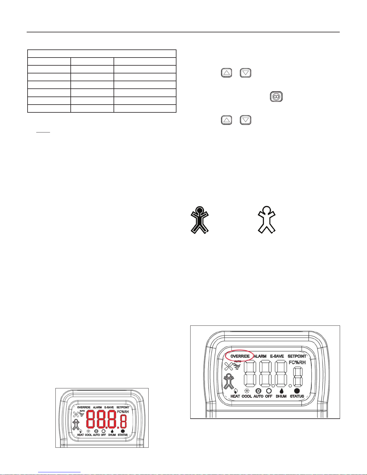
Occupied Button (Occupied/
Unoccupied Request):
Note: Terminal “U” opens HI to source power on power-up
“Occcupied”
When the “Occupancy” Button is pushed, the current “Oc-
cupied” or “Unoccupied” status of the sensor will be toggled
to the opposite condition for 20 seconds. Both the display and
“U” terminal output reect the new status during the 20
seconds. If a conrmation signal is received from the control-
ler into the Status Input terminal “1” within 20 seconds, then
the new occupancy condition remains; otherwise the “U” ter-
minal will return to the original state and the “Occupied” Icon
will ash the desired occupancy state every 8 seconds.