Daikin BRC073A1 User manual

Installation and operation manual
1BRC073A1
Wired user interface
4P392190-1 – 2014.11
Table of contents Page
About this document ......................................................................................... 1
Operation .......................................................................................................... 1
1. General safety precautions............................................................... 1
2. Features and functions ..................................................................... 1
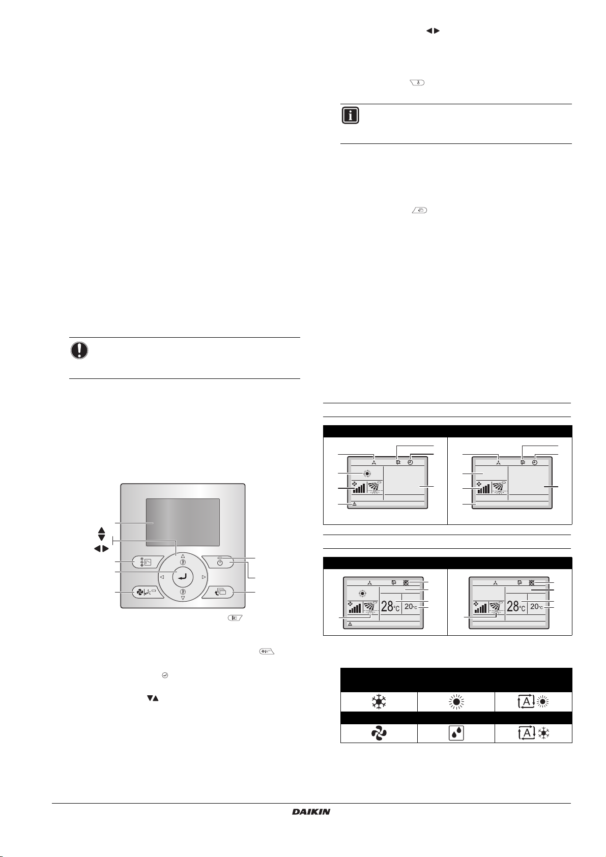
3. Name and function of switches......................................................... 2
4. Name and function of icons .............................................................. 2
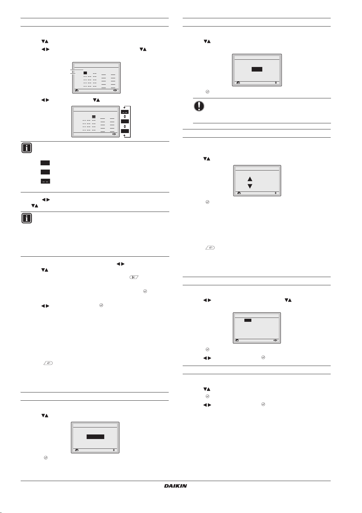
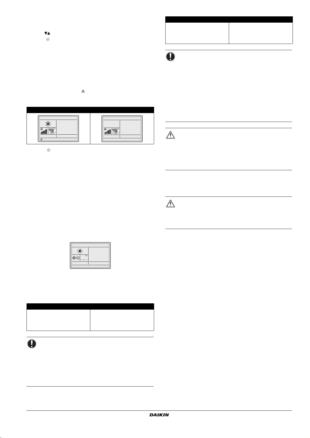
5. Description of the operation modes .................................................. 3
6. Basic operation method .................................................................... 3
7. Description of the items in the main menu........................................ 4
8. Airflow Direction................................................................................ 4
9. Energy Saving Options ..................................................................... 4
10. Schedule........................................................................................... 4
11. Maintenance Information .................................................................. 5
12. Configuration..................................................................................... 5
13. Current Settings................................................................................ 5
14. Clock & Calendar.............................................................................. 5
15. Language.......................................................................................... 6
16. Error code display............................................................................. 6
17. Main menu structure......................................................................... 6
18. ʺMode Conflictʺmessage.................................................................. 6
19. Combined use of the wired and wireless user interface ................... 6
Installation......................................................................................................... 7
1. General safety precautions............................................................... 7
2. What is in the box ............................................................................. 7
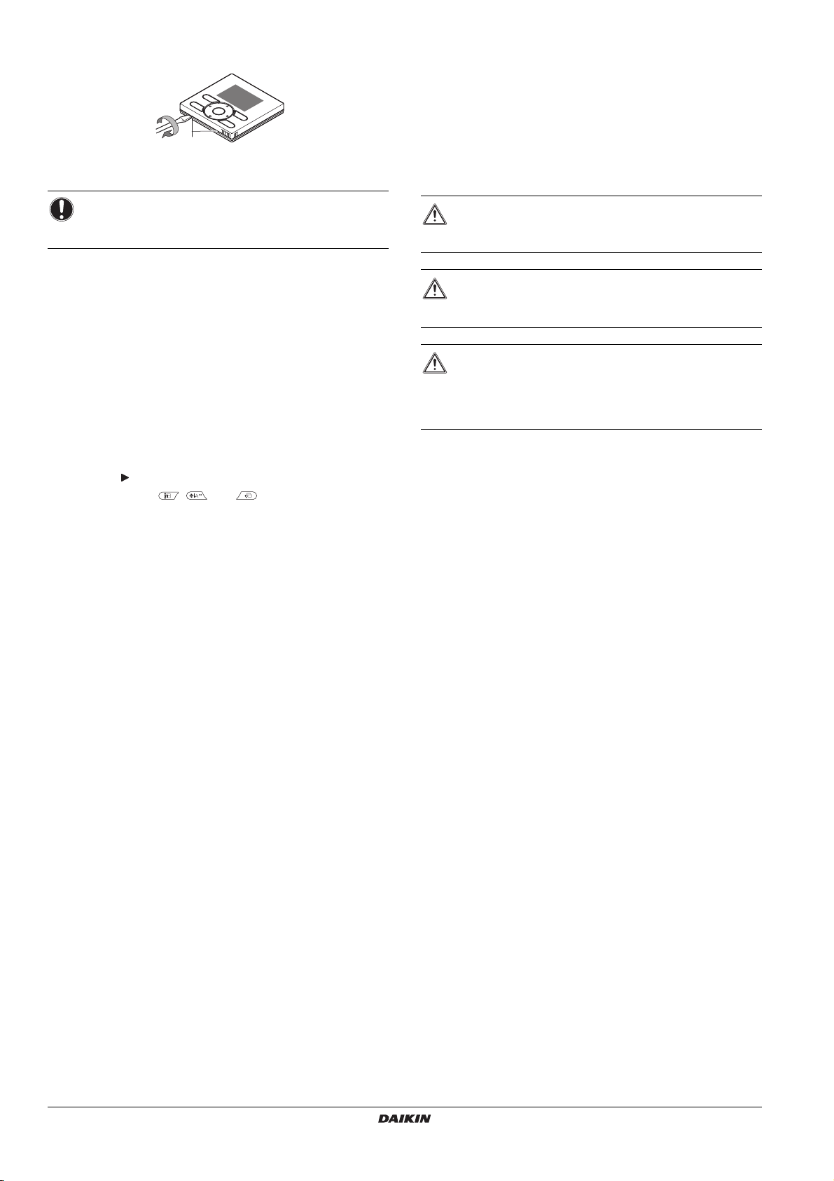
4. Fasten the user interface .................................................................. 7
6. Wire the indoor unit........................................................................... 8
7. Attach the upper case....................................................................... 8
8. Remove the upper case.................................................................... 9
9. Power on........................................................................................... 9
10. Enable/disable the menu/enter and cancel button............................ 9
Maintenance ..................................................................................................... 9
1. General safety precautions............................................................... 9
Appendix......................................................................................................... 10
The original instructions are written in English. All languages are
translations of the original instructions.
About this document
Target audience
Authorized installers + end users
Documentation set
This document is part of a documentation set. The complete set
consists of:
Latest revisions of the supplied documentation may be available on
the regional Daikin website or via our dealer.
For detailed instructions refer to the installation videos available on
http://www.daikineurope.com/support-and-manuals/product-
information/. More specifically, for how to connect to the S21
connector, refer to the installation videos of the Daikin online
controller.
Operation
See the user reference guide for more details.
1. General safety precautions
Please read these general safety precautions carefully before
installing the user interface.
Failure to follow these instructions properly may result in property
damage or personal injury, which may be serious depending on the
circumstances.
2. Features and functions
The state of the art user interface offers full control over your
installation.
1 BASIC USER INTERFACE
The basic user interface functions are:
ON/OFF,
operation mode change-over,
temperature adjustment,
fan speed adjustment,
airflow direction adjustment.
BRC073A1 Wired user interface Installation and
operation manual
Document Contains... Format
Installation and
operation manual Installation and operation
instructions Paper (in the box)
Installer reference
guide Preparation of the
installation, technical
specifications, reference
data,...
Digital files on http://
www.daikineurope.com
/support-and-manuals/
product-information/.
User reference
guide Detailed step-by-step
instructions and background
information for basic and
advanced usage
WARNING
Also see operation manual attached to the outdoor and
indoor unit.
WARNING
Do NOT play with the unit or its user interface. Accidental
operation by a child may result in impairment of bodily
functions and may harm health.
WARNING
Never disassemble the user interface. Touching the
interior parts may result in electric shocks or fire. Consult
your Daikin dealer or authorized contractor for internal
inspections and adjustments.
WARNING
To avoid electric shocks, do not operate with wet hands.
WARNING
Do NOT modify or repair the user interface. This may
result in electric shocks or fire. Consult your Daikin
dealer.
Do NOT relocate or reinstall the user interface by
yourself. Improper installation may result in electric
shocks or fire. Consult your Daikin dealer.
Do NOT use flammable materials (e.g. hairspray or
insecticide) near the product. Do not clean the product
with organic solvents such as paint thinner. The use of
organic solvents may cause crack damage to the
product, electric shocks, or fire.

BRC073A1
Wired user interface
4P392190-1 – 2014.11
Installation and operation manual
2
2 CLOCK FUNCTION
The clock functions are:
12/24 hours real time clock,
automatic daylight saving.
3 SCHEDULE FUNCTION
The schedule timer function can be restricted in case a
centralised control is installed via the KRP928 Interface Adapter
for Room Air Conditioner.
The schedule timer functions are:
a maximum of 5 actions can be programmed for each day of
the week,
3 independent schedules can be programmed,
schedule can be enabled/disabled at any time,
linked to a cool temperature and/or heat temperature or an
OFF operation (with or without a setback temperature),
"last Command" overrules previous command until next
scheduled command.
4 SETBACK
The setback function will maintain the room temperature in a
specific range when the user interface is turned OFF.
5 PROHIBIT BUTTONS/FUNCTION/MODE
The buttons, functions and/or operation modes can be locked to
limit the user action.
6 DETAILED DISPLAY POSSIBILITY
Additionally display the outdoor temperature or room
temperature.
7 CENTRALISED CONTROL
Possible to enable/disable certain functions/buttons of the
BRC073A1. (Only available when a centralised controller is
installed via the KRP928 Interface Adapter for Room Air
Conditioner)
3. Name and function of switches
1 OPERATION MODE SELECTOR BUTTON
Press this button to select the operation mode of your
preference.
2 FAN SPEED AND AIRFLOW DIRECTION BUTTON
Used to change the fan speed and airflow direction.
3 MENU/ENTER BUTTON
Used to display the main menu or enter the selected item.
4 UP/DOWN BUTTON
Used to raise/lower the set temperature.
Used to highlight the next item on the upper/lower side.
Used to change the selected item.
5 RIGHT/LEFT BUTTON
Used to highlight the next item on the right/left-hand side.
The display contents are changed to the next/previous
screen.
6ON/OFFBUTTON
Press to start or stop the air conditioner.
7 OPERATION LAMP
Lights up during operation.
This lamp is not lit when unit operation is OFF.
Blinks if an error occurs or when a mode conflict occurs.
8 CANCEL BUTTON
Used to return to the previous screen.
9 LCD (with backlight)
The backlight will be lit for approximately 30 seconds when
one of the buttons is pressed.
The actions linked to the buttons, except for the ON/OFF
button, are not carried out when the backlight is not lit.
4. Name and function of icons
To change between the standard display and the detailed display,
refer to "To select the display mode" in chapter "12. Configuration" on
page 5.
For detailed instructions on how to change between "With icons"
mode and "With icons and text" mode, refer to the installer reference
guide.
Standard display
Detailed display
1 OPERATION MODE
Indicates the current operation mode.
NOTICE
The room temperature is measured inside the indoor
unit.
1
9
4
5
3
2
8
6
7
INFORMATION
This is the only button that works when the backlight is
not lit.
With icons (default) With icons and text
With icons With icons and text
Operation mode
Cool Heat Auto (Heat)
Fan Dry Auto (Cool)
28
°C
1
8
4
7
6
5
2
Heat
28
°C
Error: Push Menu button
2
1
8
4
7
6
5
10
9
Fri
11:03
4
11
3
10
9
Fri
11:03
3
4
11
Error: Push Menu button
Heat

Installation and operation manual
3BRC073A1
Wired user interface
4P392190-1 – 2014.11
2 FAN SPEED
Indicates the fan speed that is set for the air conditioner.
The fan speed will not be displayed if the air conditioner does
not have the fan speed control function.
3 AIRFLOW DIRECTION
Displays the airflow direction that is set for the air conditioner.
The airflow direction will not be displayed if the air conditioner
does not have the airflow direction control function.
Displayed only when the air conditioner is in operation.
4 SET/SETBACK TEMPERATURE DISPLAY
When the unit is turned ON, the temperature that is set for
the air conditioner is displayed.
When the unit is turned OFF and setback is disabled, the
temperature that is set for the air conditioner is displayed.
When the unit is turned OFF and setback is enabled, the
temperature that is set for the setback function is displayed in
smaller digits.
5ERROR
Indicates a unit error or warning.
Push the button (if enabled) to display the error message
and the maintenance information.
6 TIMER ENABLED
Indicates that the schedule timer or the OFF timer is enabled.
7 UNDER CENTRALISED CONTROL
Indicates that the system is under the management of central
control equipment (optional accessories) and the operation of
the air conditioner through the user interface is prohibited.
8 SETBACK
The setback icon flashes when the unit is turned ON under
setback control.
9 CLOCK (12/24 Hours real time clock)
Indicates that the clock is set.
If the clock is not set, -- : -- will be displayed.
10 DETAILED SELECTION
Is displayed when the detailed display mode is selected.
No detailed items are selected by default.
11 TIMER PROBLEM
Indicates that the clock needs to be set again.
The schedule timer function will not work unless the clock is
set again.
5. Description of the operation modes
1 FAN ONLY OPERATION
In this mode, the air is circulated without being heated or cooled.
2 DRY OPERATION
In this mode, the air humidity will be lowered by intermittently
turning the air conditioner ON in cooling and OFF again to
minimise the temperature decrease.
The temperature and fan speed are controlled automatically
and cannot be controlled by the user interface.
Dry operation will not function if the room temperature is too
low.
3 AUTOMATIC OPERATION
In this mode, the user interface will automatically switch
between heating and cooling as required by the setpoint.
4 COOLING OPERATION
In this mode, cooling will be activated as required by the setpoint
or setback operation.
5 HEATING OPERATION
In this mode, heating will be activated as required by the
setpoint or setback operation.
6 SETBACK
The setback function will maintain the room temperature in a
specific range when the user interface is turned OFF. This is
done by temporarily starting the air conditioner that was
previously turned OFF by the user, the schedule function or the
OFF timer.
For example:
If the room temperature drops below 10°C, heating is started
automatically. If after half an hour the temperature increases
to 12°C or above, the user interface returns to its original
state.
If the room temperature goes above 35°C, cooling is started
automatically. If after half an hour the temperature decreases
to 33°C or below, the user interface returns to its original
state.
The differential can be adjusted in the setback menu. The
setback temperature can be set while the unit is turned OFF on
the basic screen, or can be set in the schedule.
The status of setback (enabled/disabled) can be seen in the
Energy Saving List.
By default, the setback function is disabled. Before enabling
it, first consult the detailed information about
SETBACK
in the
user reference guide.
6. Basic operation method
AOperation mode
BTemperature:
Indicates the temperature set for the air conditioner.
CFan speed.
DAirflow direction
1 Push several times until the desired operation mode
Cool
,
Heat
,
Fan
,
Dry
or
Auto
is selected.
2 Push . The operation lamp (green) will be lit and the air
conditioner will start operating.
3 Use to set the temperature.
4 Push to select:
the desired fan speed from
Auto
,
low
,
medium-low
,
medium
,
medium-high
or
high
(depending on the model).
the desired
air flow direction
,
swing
or
no swing
.
5 Push . The operation lamp will turn OFF and the air
conditioner will stop operating.
Additional features of the controller: KEY LOCK
1 Disable the Menu/Enter and Cancel button. To disable, refer to
"10. Enable/disable the menu/enter and cancel button" on page 9.
2 Push for 4 seconds to enable the key lock mode.
3 To cancel the key lock mode, push for 4 seconds.
INFORMATION
When in
Dry
mode, the fan speed cannot be set.
28°C
A
C
B
D

BRC073A1
Wired user interface
4P392190-1 – 2014.11
Installation and operation manual
4
7. Description of the items in the main menu
By default, the main menu can be accessed. To disable, refer to
"10. Enable/disable the menu/enter and cancel button" on page 9.
1 AIRFLOW DIRECTION
Change the
Airflow Direction
.
2 ENERGY SAVING OPTIONS(1)
Energy Saving List
Enable or disable the Energy Saving Options.
Setpoint Range
The setpoint temperature range can be restricted for the
Cooling
,
Heating
and
Auto
mode .
Setback Condition
Set the setback differential temperature beyond which the
unit returns to the OFF state.
Setpoint Auto Reset
Change the temperature setpoint to a preset temperature
setpoint after running for a set period of time, even if the
temperature setpoint has changed.
OFF Timer
The air conditioner is turned OFF automatically after the
selected time each time the air conditioner is activated.
3 SCHEDULE(2)
Select when the operation modes start and/or stop for each
day of the week.
Up to 5 actions can be set for each day.
Both operation modes (
normal
and
setback
) can be selected.
Additionally the holiday settings and schedule nr. can be set.
4 MAINTENANCE INFORMATION
Display the service contact.
5 CONFIGURATION
Switch between the standard and detailed display. When the
detailed display is selected, the room temperature or outdoor
temperature can be displayed on the basic screen.
6 CURRENT SETTINGS
Display a list of the current settings of the available items.
7 CLOCK & CALENDAR
Configure the date and time. The time can be displayed in either
a 12 hour or 24 hour time format.
8 LANGUAGE
Choose the language depending on the language pack installed.
8. Airflow Direction
1 Display the
Airflow Direction
screen (refer to "17. Main menu
structure" on page 6).
2 Select the desired airflow direction from
Swing
or
Swing stop
using
the buttons.
3 Push the button to confirm the settings and return to the basic
screen.
9. Energy Saving Options
For more information refer to the detailed user reference guide.
10. Schedule
The schedule can be restricted in case a centralised control is
installed via the KRP928 interface adapter for Room Air Conditioner.
To enable/disable the schedule
1 Display the
Enable/Disable
screen (refer to "Appendix" on page 10).
2 Press the buttons to select
Enable
or
Disable
.
3 Push to display the confirmation screen.
4 Use to select
Yes
and push .
To select the schedule number
1 Display the
Select Schedule
screen (refer to "Appendix" on page 10).
2 Use to change the setting to
Schedule nr 1
,
Schedule nr 2
, or
Schedule nr 3
.
3 Push to display the confirmation screen.
4 Use to select
Yes
and push .
To use the holidays
The schedule timer will be disabled for the days that have been set
as a holiday.
1 Display the
Holidays
screen (refer to "Appendix" on page 10).
2 Use to select the desired day. Push to display to set
the holiday.
3 Push to display the confirmation screen.
4 Use to select
Yes
and push .
NOTICE
Function availability depends on the indoor unit type.
(1) Setback, Setpoint Range, Setback Condition and Setpoint Auto Reset
should not be used when a centralised controller is installed via the
KRP928 Interface Adapter for Room Air Conditioner.
(2) The schedule will not be available when a centralised controller is installed
via the KRP928 Interface Adapter for Room Air Conditioner.
NOTICE
Depending on the outdoor unit, the outdoor temperature is
not visible when the indoor unit is OFF.
Airflow Direction
Direction1
Swing
SettingReturn
Direction2
Swing stop
INFORMATION
There are 2 possible directions:
The available airflow directions depend on the indoor
unit type.
Up/down Left/right
Return Setting
Enable/Disable
Schedule
Disable
Setting
Select Schedule
Schedule
Schedule nr 1
Return
Return Setting
Schedule
Holidays
Multiple Selection
Sun Mon Tue Wed Thu Fri Sat

Installation and operation manual
5BRC073A1
Wired user interface
4P392190-1 – 2014.11
To change the schedule settings of the selected schedule nr
1 Display the
Settings
screen (refer to "Appendix" on page 10).
2 Use to select the desired day (1).
3 Use to highlight the Operation start
Time
and to set the
desired Operation start
Time
(2).
4 Use to highlight
Act
and to select the desired action.
5 Use to highlight the cooling and heating temperature and
to select the desired value.
6 To set a different day of the week, use to highlight the day.
Use to change the day.
7 To copy all actions of the previous day, push while the day
to be set is highlighted.
8 When all the schedule settings are completed, push to display
the confirmation screen.
9 Use to select
Yes
and push .
11. Maintenance Information
1 Display the
Maintenance Information
screen (refer to "Appendix" on
page 10).
2 The phone number for the
Contact info
will appear at the top of
the screen.
3 Push to return to the
Main Menu
.
12. Configuration
To select the display mode
1Display the
Display Mode
screen (refer to "Appendix" on page 10).
2Use to change the setting to
Standard
or
Detailed
.
3 Push to confirm the setting. The basic screen is displayed.
To select the detailed display item
1 Display the
Display Item
screen (refer to "Appendix" on page 10).
2 Use to change the setting to
None
,
Outside Air Temp
or
Room
Temp
.
3 Push to confirm the setting. The basic screen is displayed.
To adjust the contrast of the LCD
1 Display the
Contrast adjustment
screen (refer to "Appendix" on
page 10).
2 Use to change the contrast.
3 Push to confirm the setting.
13. Current Settings
1 Display the
Current Settings
screen (refer to "Appendix" on page 10).
2 A list of the status of the current settings is displayed.
3 Push to return to the
Main Menu
.
14. Clock & Calendar
To set the date & time
1 Display the
Date & Time
screen (refer to "Appendix" on page 10).
2 Use to move the highlighted item and to set
Year
,
Month
,
Day
and
time
.
3 Push to display the confirmation screen.
4 Use to select
Yes
and push .
To set the hour format (12/24 hours)
1 Display the
12H/24H Clock
screen (refer to "Appendix" on page 10).
2 Use to select
12 H
or
24H
.
3 Push to display the confirmation screen.
4 Use to select
Yes
and push .
INFORMATION (Act column)
There are 3 types of operations:
The temperature setpoints can be configured.
The setback temperature setpoints can be configured.
The temperature and setback temperature setpoints
are disabled.
INFORMATION (Cool and Heat column)
__: Indicates that the temperature and setback
temperature setpoint for this time period are not specified.
The last active setpoint will be used.
- -: Indicates that the setback function is disabled for this
time period.
(1
)
Setting
Schedule nr 1
Mon
Time Act Cool Heat
–6:00
:
:
:
:
Return
(2
)
Setting
Schedule nr 1
Mon
Time Act Cool Heat
–6 :00
:
:
:
:
ON
OFF
ON
OFF
Return Setting
Display Mode
Display
Standard
NOTICE
The room temperature is measured inside the indoor
unit.
Return Setting
Display Item
Display
None
Return Setting
Dark
Light
Contrast Adjustment
Date & Time
Return
0:00
Wednesday
1Day
1Month
2014Year
Setting

BRC073A1
Wired user interface
4P392190-1 – 2014.11
Installation and operation manual
6
15. Language
1 Display the
Language
screen (refer to "Appendix" on page 10).
2 Use to select the language.
3 Push to confirm the setting. The basic screen is displayed.
Which languages are available depend on the language pack
installed.
For more information about the available languages, refer to the
detailed user reference guide.
16. Error code display
1 If an error occurs, the icon or text
Error: Push Menu button
(depending on screen setting) will apear and the operation lamp
will blink.
2 Push . The error code will blink and the
Contact Info
will be
displayed.
17. Main menu structure
See "Appendix" on page 10.
18. ʺMode Conflictʺmessage
Only applicable in case of a multi system (multiple indoor units
connected to the outdoor unit). When multiple indoor units are
instructed to operate simultaneously, but in different operation
modes, an operation mode conflict occurs:
The operation lamp flashes
MODE CONFLICT
appears on the user interface
The units that do not have priority enter standby mode
This is not a malfunction. To solve the conflict, make the units that do
not have priority run in the same operation mode as that of the unit
that has priority. Which unit has priority depends on whether the
Priority Room setting is present and/or active:
19. Combined use of the wired and wireless user
interface
With icons With icons and text
If... Then...
The
Priority Room
setting is present
and active. The operation mode of the indoor
unit to which the
Priority Room
setting
is applied takes priority. In case of an
operation mode conflict, the other
units will enter standby mode.
NOTICE
COOL
,
DRY
and
FAN
operation can be used
simultaneously.
If the conflict is not solved manually, non-priority units
will automatically resume operation as soon as the
priority unit stops operating.
It is NOT possible to enter the menu when the user
interface indicates the
MODE CONFLICT
message.
28°C
28°C
Error: Push Menu button
Cool
10
°C
Mode conflict
If... Then...
The
Priority Room
setting is not present
OR present but not active. The operation mode of the indoor
unit that was turned on first takes
priority. In case of an operation mode
conflict, the units that were turned on
later will enter standby mode.
NOTICE
COOL
,
DRY
and
FAN
operation can be used
simultaneously.
Units running in
HEAT
operation mode always have
priority over units running in
FAN
operation mode,
even if they were not turned on first.
When solving the conflict, it is possible to make the
non-priority units run in
AUTO
operation mode: they will
automatically start operation in the same operation
mode as that of the priority unit.
It is NOT possible to enter the menu when the user
interface indicates the
MODE CONFLICT
message.
CAUTION
The
MODE CONFLICT
can also happen to units that are
turned on by the
setback
function. This means that due to
priority, they will not run and consequently will not be able
to maintain the temperature in the room. Please consider
the use of the
setback
feature in a multi system carefully to
avoid situations like these.
CAUTION
Avoid using the wired user interface and the standard
wireless user interface at the same time.
When combining the user interfaces, refer to the user
reference guide for the phenomena that can occur.

Installation and operation manual
7BRC073A1
Wired user interface
4P392190-1 – 2014.11
Installation
See the installer reference guide for more details.
1. General safety precautions
Please read these general safety precautions carefully before
installing the user interface.
Improper installation or attachment of equipment or accessories
could result in electric shock, short-circuit, leaks, fire or other damage
to the equipment or personal injury.
If unsure of installation procedures or use, always contact your dealer
for advice and information.
Do NOT install the user interface by yourself. Improper installation
may result in electric shocks or fire. Consult your Daikin dealer.
After completing the installation:
conduct a trial operation to check for faults,
explain the customer how to operate the air conditioner with the
aid of the Operation part of this manual,
ask the customer to store this manual for future reference.
2. What is in the box
1User interface (upper and lower part)
2Wire harness (S21)
3Adapter
4Wood screws+wall plugs
5Small screws
6Clamp
7Tape
8Wiring retainer
9Installation and operation manual
3. Requirements
To make the connection between the user interface (S1) and the
adapter (S19), the BRCW901A03 or BRCW901A08 option cable
is required.
The S21 connector is not present on some indoor units. In this
case, the KRP980 should be installed first.
4. Fasten the user interface
1Wall mounting, fasten with the 2 included wood screws
(Ø3.5×32) and plugs.
2Switch box mounting, fasten with the 2 included small
screws (M4×16).
For the field-supplied switch box, use optional accessory KJB111A or
KJB211A.
WARNING
Carefully read these instructions before installation. They
will tell you how to install, how to configure and how to use
the unit properly. Keep this manual in a handy place for
future reference.
This is an option to be used in combination with Daikin
units. Refer to the installer reference guide and user
reference guide of the units for installation and operation
instructions.
WARNING
All field wiring and components must be installed by an
installer and must comply with the applicable legislation.
NOTICE
When the thermo function of the user interface is used,
select the installation location while considering it should
be a place:
where the average temperature in the room can be
detected,
which is not exposed to direct sunlight,
which is not near a heat source,
which is not affected by the outside air or air draught
due to, for example, opening/closing of doors or the
like,
where the front panel and the display are kept clean,
where the temperature is between –10°C and 50°C,
where the relative humidity is max. 95%,
that is NOT located outdoors.
NOTICE
Do NOT install the user interface:
Near machinery emitting electromagnetic radiation.
Electromagnetic radiation may disturb the operation of
the control system and result in a malfunction of the
unit.
In moist areas or places where it may be exposed to
water. If water enters the user interface, electric
shocks may be caused and the inner electronics may
fail.
WARNING
Consult your local dealer regarding relocation and
reinstallation of the user interface.
Item No. Length
BRCW901A03 3 m
BRCW901A08 8 m
INFORMATION
Select a flat surface for installation, if possible.
Do not tighten the installation screws too much to
avoid deforming the lower case.
1× 2×1× 1× 4×
+
12345
3× 1× 1× 1×
6789
1
2
2

BRC073A1
Wired user interface
4P392190-1 – 2014.11
Installation and operation manual
8
5. Securing the user interface adapter
Remove the upper case of the user interface adapter and secure the
lower case assembly.
6. Wire the indoor unit
For detailed instructions refer to the installation videos available on
http://www.daikineurope.com/support-and-manuals/product-
information/. More specifically, for how to connect the S21 connector,
refer to the installation videos of the Daikin online controller.
3 methods:
1 from the rear,
2 from the left,
3 from the top,
1indoor unit
2notch the part for the wiring to pass through with nippers,
etc.
3secure the wiring to the upper case using the wiring
retainer and clamp.
Connect the user interface (S1) to the adapter (S19), and the adapter
(S6) to the indoor unit (S21):
7. Attach the upper case
Align the upper case with the tabs of the lower
case (6 points) and insert the upper case (begin
with the bottom part).
Mounting with supplied wood screws
(Ø3.5×16) Mounting with supplied double-face
adhesive tape
3
1
2
1×
3
1
2
PCB
PCB
S19 S21
S6
S1
1
1×
BRCW901A
2PCB
1×
2
PCB
3
S19 S21
S6
S1
1
BRCW901A
S1 and S19 connection S6 and S21 connection
INFORMATION
When wiring, run the wiring away from the power supply
wiring in order to avoid receiving electric noise (external
noise).
NOTICE
Earth both ends of the BRCW901A* option cable.
NOTICE
Be careful not to pinch the wiring when attaching.
NOTICE
1 The switch box and connection wiring are not
included.
2 Do not directly touch the PCB with your hand.
1×
3
3
3
PCB
S19 S21
S6
1
2
S1
PCB
BRCW901A
2
345
H JST

Installation and operation manual
9BRC073A1
Wired user interface
4P392190-1 – 2014.11
8. Remove the upper case
Insert a slot screwdriver into the slots in the lower case (2 places), to
remove the upper case.
9. Power on
1 Turn on the power.
2
Checking the connection
.
Please stand by
. is displayed.
3 After a few seconds, the basic screen is displayed.
10. Enable/disable the menu/enter and cancel
button
By default, the menu/enter and cancel buttons are enabled.
To enable/disable the menu/enter and cancel button in the basic
screen, proceed as follows:
1 Keep the button pressed.
2 Press the 3 keys , , and simultaneously.
3 Press the buttons for a second, then release them.
Refer to the detailed installer reference guide for more detailed
installation instructions concerning:
User interface installation procedure,
Functions and menu items of the user interface buttons,
Field settings,
Test operation method,
Checking procedure of Error History,
Registration method of the Maintenance Contact,
Clock & Calendar (see also "14. Clock & Calendar" on page 5),
Language (see also "15. Language" on page 6),
Prohibit buttons,
Prohibition Function,
Prohibit Mode,
Software update with Updater.
Maintenance
1. General safety precautions
Wipe the LCD display and the rest of the surface of the user interface
with a dry cloth when they become dirty.
If the dirt on the surface cannot be removed, soak the cloth in neutral
detergent diluted with water, squeeze the cloth tightly, and clean the
surface. Wipe the surface with a dry cloth afterwards.
NOTICE
The user interface PCB is mounted on the upper case. Be
careful not to damage the PCB with the slot screwdriver.
1
WARNING
Do not use any paint thinner, organic solvent, or strong
acid.
WARNING
Do not wash the user interface. Doing so may cause
electric leakage and result in electric shocks or fire.
WARNING
Be sure to stop the operation of the air conditioner and turn
OFF the power supply breaker when performing
maintenance. Failure to do so may result in electric shocks
or injury.

BRC073A1
Wired user interface
4P392190-1 – 2014.11
Installation and operation manual
10
Appendix
(8)
28°C
Main Menu
Airflow Direction
Energy Saving Options
Schedule
Maintenance Information
Configuration
Current Settings
Clock & Calendar
Language
Airflow Direction
(9)
(10)
(11)
(12)
(13)
(14)
(15)
Energy Saving Options
Energy Saving List
Setpoint Range
Setback Condition
Setpoint Auto Reset
Off Timer
Schedule
Enable/Disable
Select Schedule
Holidays
Settings
Maintenance Information
Configuration
Display
Contrast Adjustment
Display
Display Mode
Display Item
Current Settings
Language
Clock & Calendar
Date & Time
12H/24H Clock

4P392190-1 2014.11
Copyright 2014 Daikin
Table of contents
Other Daikin Recording Equipment manuals