Installation manual
7
EKRUMC
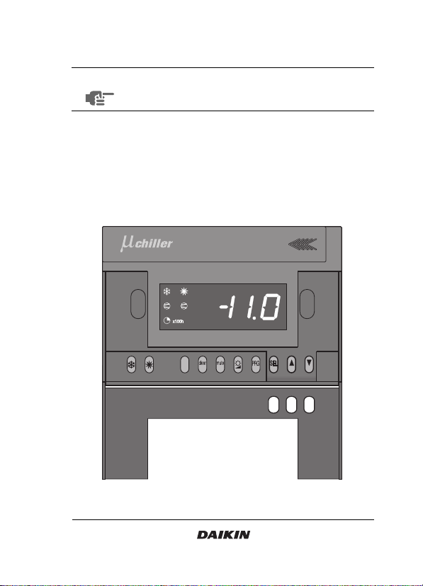
Remote user interface
4PW16029-1
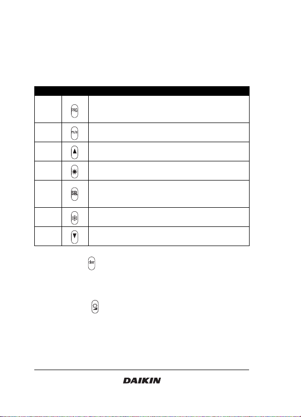
Keys provided on the remote user interface:
The function carried out when the user presses one of these keys
depends on the status of the controller and the unit at that specific
moment.
The table shows the corresponding keys of the digital controller on
the unit and the remote user interface.
The extra button can be used to reset the warnings when pressed
for approximately 5 seconds. This button has the same function as
pressing the
A
and
Z
keys on the digital controller on the unit
simultaneously for approximately 5 seconds.
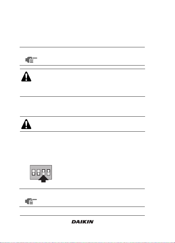
The extra button can be used to select three different contrast
levels on the display of the remote user interface.
On unit Remote
EE
EE
key, to enter the scroll list of user parameters, to
confirm a parameter modification and to return to
normal operation.
OO
OO
key, to de-activate the buzzer in the case of an
alarm.
AA
AA
key, to scroll through the list of direct or user
parameters or to raise a setting.
YY
YY
key, to start the unit in heating mode or to switch
the unit off when heating mode is active.
RR
RR
key, to enter the scroll list of direct parameters or
to switch between a parameter's code and its
value.
II
II
key, to start the unit in cooling mode or to switch
the unit off when cooling mode is active.
ZZ
ZZ
key, to scroll through the list of direct or user
parameters or to lower a setting.