Daikin EKFCMBCB7 User manual

12
3
4
5
A
B
C
Modbus interface PCB Kit
INSTALLATION MANUAL
EKFCMBCB7
1
3
SS1 SS2
OFF
ON
452
1
2
1
2
4PWEN65443-1B.book Page 1 Tuesday, June 29, 2021 11:58 AM

EKFCMBCB7
Modbus interface PCB kit
4PW65443-1B – 2021.06
Installation manual
1
CONTENTS page
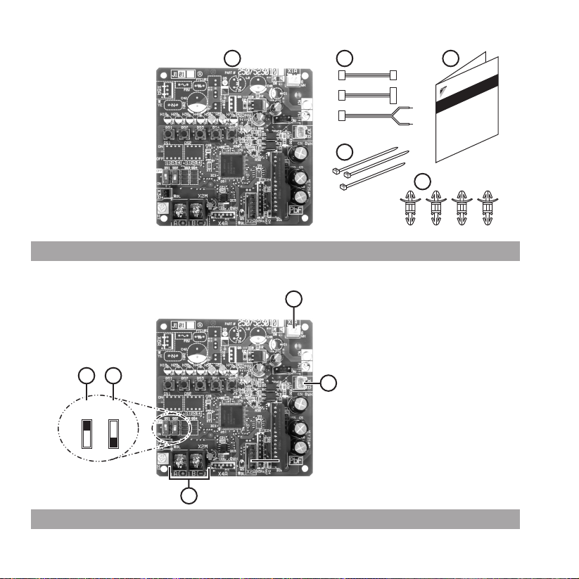
Content of kit EKFCMBCB7.................................................................................................................3
Name of parts ......................................................................................................................................3
Specification of communication wires..................................................................................................3
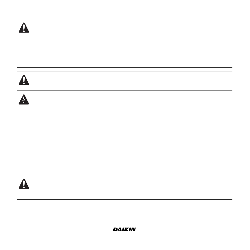
Installation method in combination with FWF models..........................................................................4
Installation method in combination with FWC models .........................................................................4
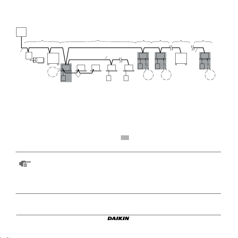
External connection possibility ............................................................................................................5
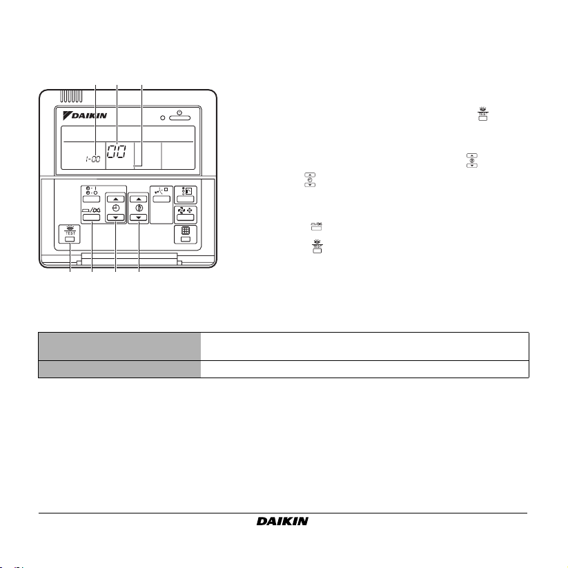
Setting of group number with the wired remote controller ...................................................................7
Operation and maintenance ................................................................................................................8
EKFCMBCB7 Modbus interface PCB kit Installation manual
READ THESE INSTRUCTIONS CAREFULLY BEFORE INSTALLATION.
KEEP THIS MANUAL IN A HANDY PLACE FOR FUTURE REFERENCE.
IMPROPER INSTALLATION OR ATTACHMENT OF EQUIPMENT OR ACCESSORIES
COULD RESULT IN ELECTRIC SHOCK, SHORT-CIRCUIT, LEAKS, FIRE OR OTHER
DAMAGE TO THE EQUIPMENT. BE SURE ONLY TO USE ACCESSORIES MADE BY
DAIKIN WHICH ARE SPECIFICALLY DESIGNED FOR USE WITH THE EQUIPMENT
AND HAVE THEM INSTALLED BY A PROFESSIONAL.
IF UNSURE OF INSTALLATION PROCEDURES OR USE, ALWAYS CONTACT YOUR
DAIKIN DEALER FOR ADVICE AND INFORMATION.
4PWEN65443-1B.book Page 1 Tuesday, June 29, 2021 11:58 AM

Installation manual
2
EKFCMBCB7
Modbus interface PCB kit
4PW65443-1B – 2021.06
This is an option kit for a FWF or FWC fan coil unit to switch the unit communication to Modbus RTU
(RS485) communication.
Refer to the installation manual of the fan coil unit for details on installing the fan coil unit.
The original documentation is written in English. All other languages are translations of the original
documentation.
Never squeeze bundeled cables and be sure that the cables do not come in contact with sharp
edges.
ALL FIELD WIRING AND COMPONENTS MUST BE INSTALLED BY A LICENSED
ELECTRICIAN AND MUST COMPLY WITH RELEVANT LOCAL AND NATIONAL
REGULATIONS.
THE FIELD WIRING MUST BE CARRIED OUT IN ACCORDANCE WITH THE WIRING
DIAGRAMS AND THE INSTRUCTIONS GIVEN BELOW.
TAKE CARE NOT TO BEND THE PRINTED CIRCUIT BOARD WHEN INSERTING OR
REMOVING THE CONNECTORS.
THE EQUIPMENT IS NOT INTENDED FOR USE IN A POTENTIALLY EXPLOSIVE
ATMOSPHERE.
Danger: electric shock
Switch off all power supply before removing the control box cover or before making any
connections or touching electrical parts.
WARNING
This is a class A product. In a domestic environment this product may cause radio
interference in which case the user may be required to take adequate measures.
4PWEN65443-1B.book Page 2 Tuesday, June 29, 2021 11:58 AM

EKFCMBCB7
Modbus interface PCB kit
4PW65443-1B – 2021.06
Installation manual
3
CONTENT OF KIT EKFCMBCB7
See figure 1
1Modbus interface PCB
2Wires
A: Power supply wire for FWF models
B: Power supply wire for FWC models
C: Communication wire
3Tie wraps
4Spacers
5Installation manual
NAME OF PARTS
See figure 2
1Connector to the fan coil unit PCB for power supply with wire A or B
2Connector to the fan coil unit terminal block for communication (F1/F2) with wire B
3Communication wires from the field
4SS1: Put on OFF position
5SS2: Switch to decide position of Modbus PCB in communication line
(refer to "External connection possibility" on page 5)
SPECIFICATION OF COMMUNICATION WIRES
Specifications field wiring
Wire type Twisted pair sheathed cable
Wire size 0.75~1.25 mm2
Maximum total wire length 500 m
4PWEN65443-1B.book Page 3 Tuesday, June 29, 2021 11:58 AM

Installation manual
4
EKFCMBCB7
Modbus interface PCB kit
4PW65443-1B – 2021.06
INSTALLATION METHOD IN COMBINATION WITH FWF MODELS
The installation box KRP1BA101 is needed.
Mount the installation box and PCB as explained in the installation manual of the KRP1BA101 kit.
See figure 3
1KRP1BA101 Box with Modbus PCB
2Communication wiring (to field)
3Wiring to fan coil unit PCB
4Wire X7A-F1/F2
5Wire X1A-X35A
6Tie wrap
7Hook (supplied with KRP1BA101 kit)
INSTALLATION METHOD IN COMBINATION WITH FWC MODELS
The installation box KRP1H98 is needed.
Install the installation box and PCB in the unit as explained in the installation manual of the KRP1H98
kit. The PCB needs to be mounted on the bottom of the box (see KRP2A52).
See figure 4
1KRP1H98 with Modbus PCB
2Communication wire from field
3Wire X7A-F1/F2
4Wire X1A-X38A
5Tie wrap
6Room for excess cable
4PWEN65443-1B.book Page 4 Tuesday, June 29, 2021 11:58 AM

EKFCMBCB7
Modbus interface PCB kit
4PW65443-1B – 2021.06
Installation manual
5
EXTERNAL CONNECTION POSSIBILITY
AAddress zone 1 4FWF or FWC unit that needs its own remote
controller address
BAddress zone 2
CAddress zone 3 5FWF or FWC unit that does not need its own
remote controller address
DAddress zone 4
ETermination of the Modbus communication line 6Remote controller
1Centralized control system 7Remote controller communication line
2Modbus communication line 8Transmission wiring
3Fan coil unit with integrated Modbus
communication
Fan coil unit that needs a Modbus PCB
NOTE ■Each remote rontroller communication group needs an address set by the wired
remote controller. Refer to "Setting of group number with the wired remote
controller" on page 7.
■Maximum 16 remote controller addresses can be connected to a Modbus PCB.
■Maximum 64 remote controller addresses can be used on a central remote
controller.
A
1
2
6
4
7
55
BCD
EE
2
6
4
6
4
SS2
=OFF
6
4
6
4
SS2
=OFF
SS2
=OFF
6
4
SS2
=ON
333
8
4PWEN65443-1B.book Page 5 Tuesday, June 29, 2021 11:58 AM

Installation manual
6
EKFCMBCB7
Modbus interface PCB kit
4PW65443-1B – 2021.06
NOTE ■A Modbus PCB needs to be connected on a FWF or FWC unit which has its own
remote controller address.
■Maximum 8 Modbus PCBs can be connected on a 0.75 mm2wire.
■Maximum 15 FWF or FWC units can be connected on a FWF or FWC unit which
has its own remote controller address.
NOTE ■The cable terminal (resistor) is integrated in the Modbus PCB and is enabled by
means of a DIP switch (SS2).
■In case the Modbus PCB is used as cable terminal (refer to "E: Termination of the
Modbus communication line on page 5"), the DIP switch SS2 must be set to ON,
otherwise it must be set to OFF.
■DIP switch SS1 must always be set to OFF.
4PWEN65443-1B.book Page 6 Tuesday, June 29, 2021 11:58 AM

EKFCMBCB7
Modbus interface PCB kit
4PW65443-1B – 2021.06
Installation manual
7
SETTING OF GROUP NUMBER WITH THE WIRED REMOTE CONTROLLER
The group number set with the wired remote controller is translated to a Modbus address according
to the table below
Group number
(remote controller address)
1-00 1-01
...
1-15
...
2-15
...
4-15
Modbus address 1 2 ... 16 ... 32 ... 64
SETTING
ab c
2-6 5 4 3
1Activate power to the centralized control system and
to the fan coil unit.
2While in the normal mode, hold down the button
for a minimum of 4 seconds. The controller will enter
the field set mode (c).
3Select the mode number "
00
" (b) with the button.
4Use the button to select the group number (a) for
each group. (The group number increases in the order
of
1-00
,
1-01
, ...,
1-15
,
2-00
, ...,
4-15
.)
5Press the button to set the selected group number.
6Press the button to return to the normal mode.
4PWEN65443-1B.book Page 7 Tuesday, June 29, 2021 11:58 AM

Installation manual
8
EKFCMBCB7
Modbus interface PCB kit
4PW65443-1B – 2021.06
OPERATION AND MAINTENANCE
What to do before operation
Operation and display signals
In case of a Modbus integration, before initiating operation, contact your Daikin dealer to
get the information that corresponds to your system.
LED LED colour LED is ON LED is blinking
HAP Green CPU error Normal CPU operation
H5P Orange Normal Modbus communication Modbus communication error
H6P Orange Normal fan coil unit communication Fan coil unit communication error
4PWEN65443-1B.book Page 8 Tuesday, June 29, 2021 11:58 AM

546
1
6
5
1
4
362
4 5 6
7
5
21 5
4
3
4 3 2 6
3
4
FWF
FWC
3
4
4PWEN65443-1B.book Page 1 Tuesday, June 29, 2021 11:58 AM

4PW65443-1B 2021.06
3:%3
Copyright 2011 Daikin
4PWEN65443-1B.book Page 1 Tuesday, June 29, 2021 11:58 AM
This manual suits for next models
2
Table of contents
Other Daikin Recording Equipment manuals