Operation manual
1
VAM150~2000F
Total Heat Exchanger
HRV (Heat Reclaim Ventilation)
4PW13544-1B
C
ONTENTS
Page
Safety cautions.................................................................................. 1
Names of parts.................................................................................. 1
Operation .......................................................................................... 1
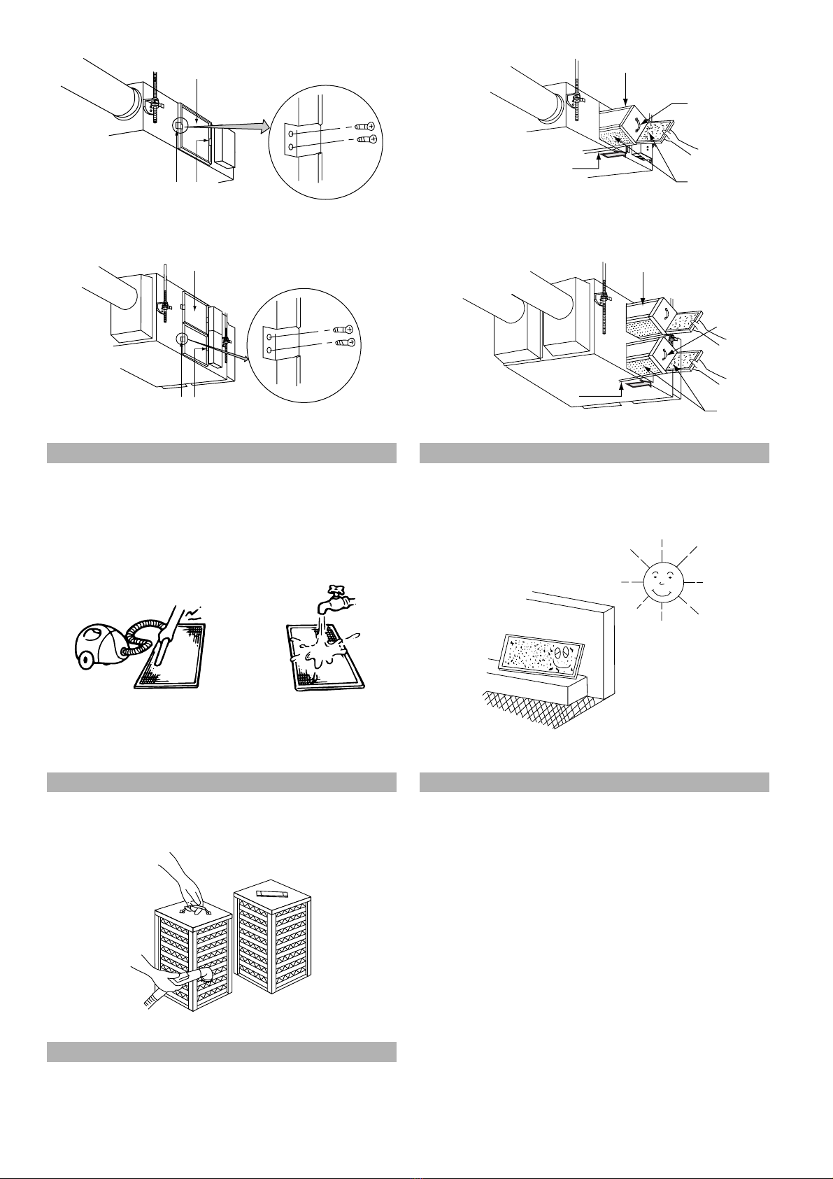
Maintenance...................................................................................... 4
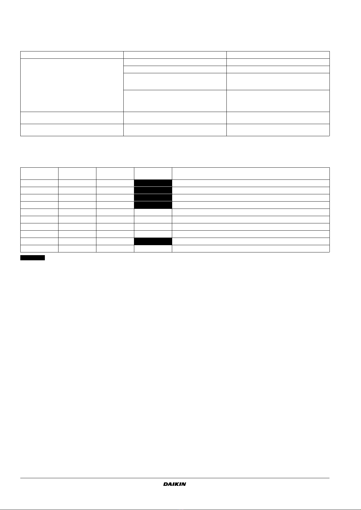
Trouble and countermeasure ............................................................ 5
S
AFETY
CAUTIONS
Read the following cautions carefully and use your equipment
properly.
There are safety cautions and tips listed here as follows:
N
AMES
OF
PARTS
Refer to figure 1 (models 150~1000F) and figure 2 (models
1500~2000F)
O
PERATION
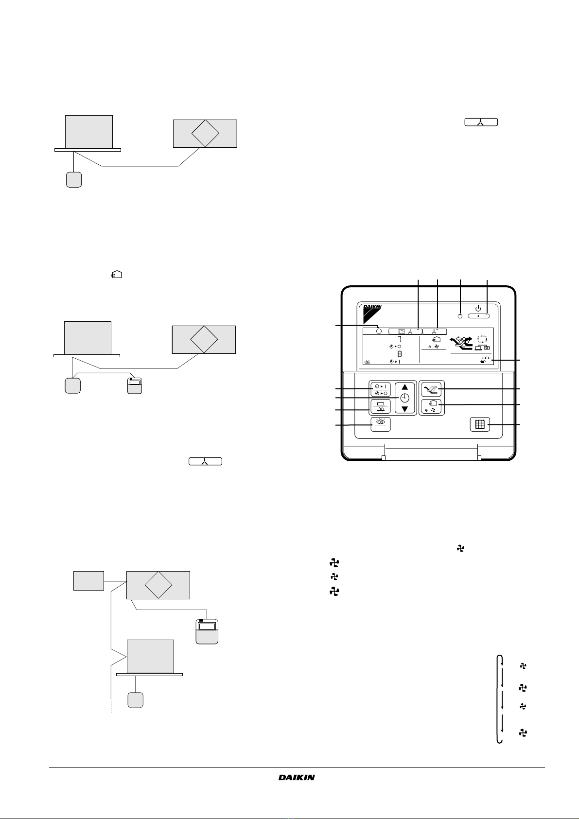
Explanation for SYSTEMS
This product is operated differently depending on the system
configuration.
For the operation of the remote controller for indoor unit and
centralized controller, refer to the instruction manual provided with
each unit.
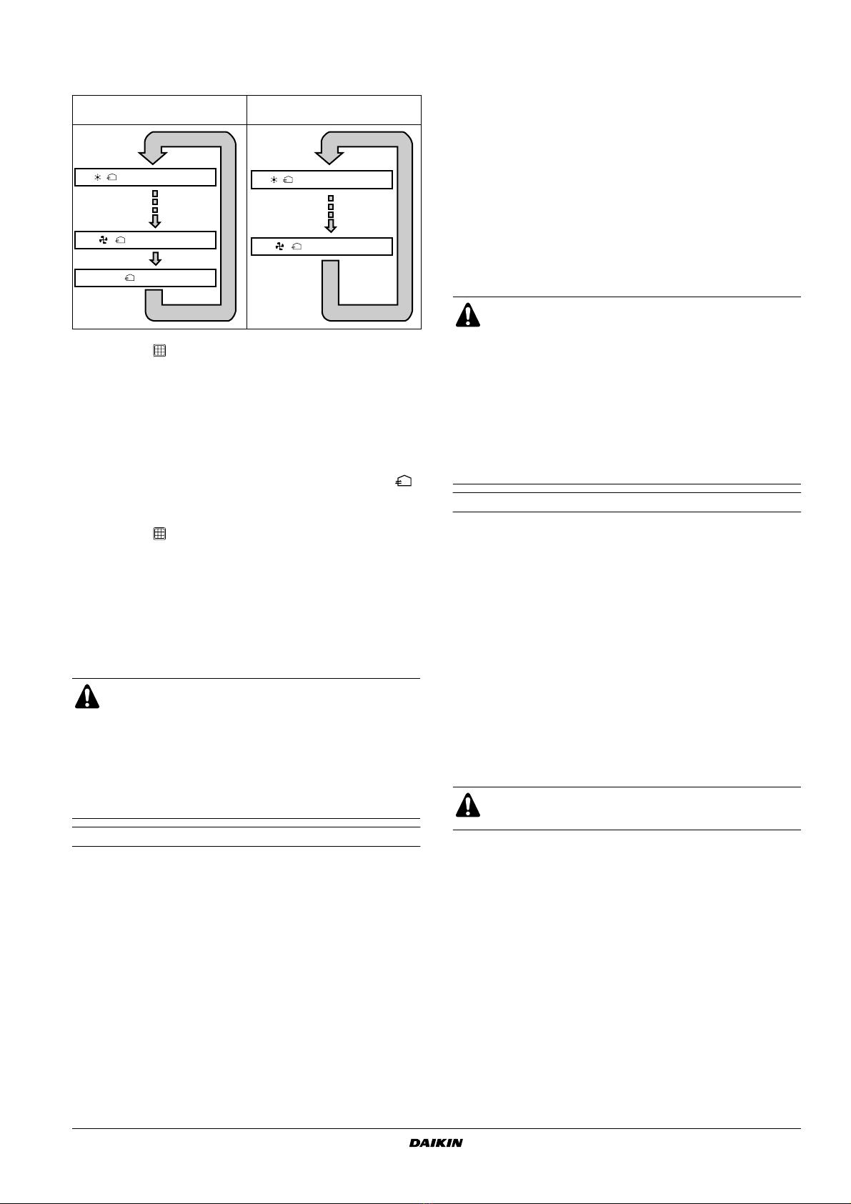
Operation for each system
Independent system
VAM150F VAM500F VAM1000F
VAM250F VAM650F VAM1500F
VAM350F VAM800F VAM2000F
Total Heat Exchanger
HRV (Heat Reclaim Ventilation)
Operation manual
HRV – Heat Reclaim Ventilation
Before using the DAIKIN HRV, be sure to read this
operation manual thoroughly. If you have any problems or
there is a malfunction, please refer to this operation
manual. Please keep this manual for your future reference
whenever you do not understand how to use it when
something is wrong with the unit during the operation.
WARNING
Improper handling can lead to such serious consequences
as death or severe injury.
NOTE
These instructions will ensure proper use of the
equipment.
Be sure to follow these important safety cautions.
Keep these warning sheets handy so that you can refer
to them if needed.
Also, if this equipment is transferred to a new user,
make sure to hand over this user’s manual to the new
user.
WARNING
■
Never inspect or service the unit by yourself.
Ask a qualified service person to perform this work.
(The qualified service person)
■
WARNING
:
Before obtaining access to terminal devices
(), all power supply circuit must be interrupted.
■
Electric shock may result. Before servicing the unit,
always shut off power.
■
Always use the air filter.
If the air filter is not used, heat exchange elements will
be clogged, possibly causing poor performance and
subsequent failure.
■
Do not change operations suddenly. It can result not
only in malfunction but also failure of switches or
relays in the body.
■
Do not use a HRV or an air suction/discharge grille in
the following places.
■
Place such as machinery plant and chemical plant
where gas, which contains noxius gas or corrosive
components of materials such as acid, alkali, organic
solvent and paint, is generated.
■
Place where combustible gas leakage is likely.
Such gas can cause fire.
WARNING
■
Place such as bathroom subjected to moisture.
Electric leak or electric shock and other failure can be
caused.
■
Place subjected to high temperature or direct flame.
Avoid a place where the temperature near the HRV
unit and the air suction/discharge air grille exceeds
40
°
C. If the unit is used at high temperature, deformed
air filter and heat exchange element or burned motor
result.
■
Place subjected to much carbon black.
Carbon black attaches to air filter and heat exchange
element, marking them unable to use.
1
Ceiling hook
2
Duct connection flange
3
Exhaust fan
4
Air filter (Long life filter)
5
Damper
6
Switch box
7
Maintenance cover
8
Heat exchange elements
9
Name plate
10
Air supply fan
11
Remote controller (Option parts)
12
Damper motor
13
EA (Exhaust air) (Exhaust air to outdoor)
14
OA (Outdoor air) (Fresh air from outdoor)
15
Maintenance space for the air filters, the heat exchange elements
and Switch box
16
RA (Return air) (Exhaust air from room)
17
SA (Supply air) (Feed air to room)
Remote controller for HRV unit
(BRC301B61)
HRV unit