Daimler Trucks North America Freightliner User manual

Introduction
This manual provides information needed to operate
and understand the vehicle and its components.
More detailed information is contained in the
Owner’s
Warranty Information for North America
booklet, and
in the vehicle’s workshop and maintenance manuals.
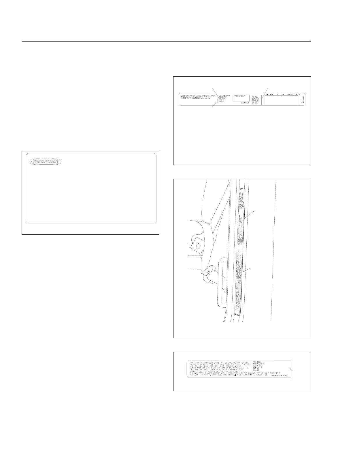
Custom-built Freightliner vehicles are equipped with
various chassis and cab components. Not all of the
information contained in this manual applies to every
vehicle. For details about components in your ve-
hicle, refer to the chassis specification pages in-
cluded in all new vehicles and to the vehicle specifi-
cation decal, located inside the vehicle.
For your reference, keep this manual in the vehicle
at all times.
IMPORTANT: Descriptions and specifications in
this manual were in effect at the time of printing.
Freightliner Trucks reserves the right to discon-
tinue models and to change specifications or
design at any time without notice and without
incurring obligation. Descriptions and specifica-
tions contained in this publication provide no
warranty, expressed or implied, and are subject
to revisions and editions without notice.
Environmental Concerns and
Recommendations
Whenever you see instructions in this manual to dis-
card materials, you should first attempt to reclaim
and recycle them. To preserve our environment, fol-
low appropriate environmental rules and regulations
when disposing of materials.
Event Data Recorder
This vehicle is equipped with one or more devices
that record specific vehicle data. The type and
amount of data recorded varies depending on how
the vehicle is equipped (such as the brand of engine,
if an air bag is installed, or if the vehicle features a
collision avoidance system, etc.).
Customer Assistance Center
Having trouble finding service? Call the Customer
Assistance Center at 1-800-385-4357 or 1-800-FTL-
HELP. Call night or day, weekdays or weekends, for
dealer referral, vehicle information, breakdown coor-
dination, or Fleetpack assistance. Our people are
knowledgeable, professional, and committed to fol-
lowing through to help you keep your truck moving.
Reporting Safety Defects
If you believe that your vehicle has a defect which
could cause a crash or could cause injury or
death, you should immediately inform the National
Highway Traffic Safety Administration (NHTSA) in
addition to notifying Daimler Trucks North America
LLC.
If the NHTSA receives similar complaints, it may
open an investigation, and if it finds that a safety
defect exists in a group of vehicles, it may order a
recall and remedy campaign. However, NHTSA
cannot become involved in individual problems
between you, your dealer, or Daimler Trucks North
America LLC.
To contact NHTSA, you may call the Vehicle
Safety Hotline toll-free at 1-888-327-4236 (TTY:
1-800-424-9153); go to www.safercar.gov; or
write to: Administrator, NHTSA, 1200 New Jersey
Avenue, SE, Washington, DC 20590. You can also
obtain other information about motor vehicle safety
from www.safercar.gov.
Canadian customers who wish to report a safety-
related defect to Transport Canada, Defect Investi-
gations and Recalls, may telephone the toll-free
hotline 1-800-333-0510, or contact Transport
Canada by mail at: Transport Canada, ASFAD,
Place de Ville Tower C, 330 Sparks Street, Ot-
tawa, Ontario, Canada K1A 0N5.
For additional road safety information, please visit
the Road Safety website at: www.tc.gc.ca/
roadsafety.
Foreword
STI-455-4 (1/12)
A24-01238-000
Printed in U.S.A.

© 2001–2012 Daimler Trucks North America LLC. All rights reserved. Daimler Trucks North America LLC is a Daimler
company.
No part of this publication, in whole or part, may be translated, reproduced, stored in a retrieval system, or transmitted
in any form by any means, electronic, mechanical, photocopying, recording, or otherwise, without the prior written per-
mission of Daimler Trucks North America LLC. For additional information, please contact Daimler Trucks North
America LLC, Service Systems and Documentation, P.O. Box 3849, Portland OR 97208–3849 U.S.A. or refer to
www.Daimler-TrucksNorthAmerica.comand www.FreightlinerTrucks.com.
Foreword

Contents
Chapter Page
Introduction, Environmental Concerns and Recommendations,
Event Data Recorder, Customer Assistance Center, Reporting
Safety Defects . . . . . . . . . . . . . . . . . . . . . . . . . . . . . . . . . . . . . . . . . . . . . . . . . . . . . Foreword
1Vehicle Identification . . . . . . . . . . . . . . . . . . . . . . . . . . . . . . . . . . . . . . . . . . . . . . . . . . . . . . 1.1
2Vehicle Access . . . . . . . . . . . . . . . . . . . . . . . . . . . . . . . . . . . . . . . . . . . . . . . . . . . . . . . . . . 2.1
3Instruments . . . . . . . . . . . . . . . . . . . . . . . . . . . . . . . . . . . . . . . . . . . . . . . . . . . . . . . . . . . . . 3.1
4Controls . . . . . . . . . . . . . . . . . . . . . . . . . . . . . . . . . . . . . . . . . . . . . . . . . . . . . . . . . . . . . . . . 4.1
5Cab Features . . . . . . . . . . . . . . . . . . . . . . . . . . . . . . . . . . . . . . . . . . . . . . . . . . . . . . . . . . . 5.1
6Heater, Ventilator and Air Conditioner . . . . . . . . . . . . . . . . . . . . . . . . . . . . . . . . . . . . . . . . 6.1
7Engines . . . . . . . . . . . . . . . . . . . . . . . . . . . . . . . . . . . . . . . . . . . . . . . . . . . . . . . . . . . . . . . . 7.1
8Drivetrain . . . . . . . . . . . . . . . . . . . . . . . . . . . . . . . . . . . . . . . . . . . . . . . . . . . . . . . . . . . . . . . 8.1
9Steering and Brake Systems . . . . . . . . . . . . . . . . . . . . . . . . . . . . . . . . . . . . . . . . . . . . . . . 9.1
10 Fifth Wheels and Trailer Couplings . . . . . . . . . . . . . . . . . . . . . . . . . . . . . . . . . . . . . . . . . 10.1
11 Pretrip and Post-Trip Inspections and Maintenance . . . . . . . . . . . . . . . . . . . . . . . . . . . . 11.1
12 Cab Appearance . . . . . . . . . . . . . . . . . . . . . . . . . . . . . . . . . . . . . . . . . . . . . . . . . . . . . . . . 12.1
13 In an Emergency . . . . . . . . . . . . . . . . . . . . . . . . . . . . . . . . . . . . . . . . . . . . . . . . . . . . . . . 13.1
14 Headlight Aiming . . . . . . . . . . . . . . . . . . . . . . . . . . . . . . . . . . . . . . . . . . . . . . . . . . . . . . . . 14.1
15 Hybrid Electric Vehicle . . . . . . . . . . . . . . . . . . . . . . . . . . . . . . . . . . . . . . . . . . . . . . . . . . . 15.1
16 Natural Gas Vehicle . . . . . . . . . . . . . . . . . . . . . . . . . . . . . . . . . . . . . . . . . . . . . . . . . . . . . 16.1
Index . . . . . . . . . . . . . . . . . . . . . . . . . . . . . . . . . . . . . . . . . . . . . . . . . . . . . . . . . . . . . . . . . . I.1

1
Vehicle Identi cation
Vehicle Specification Decal . . . . . . . . . . . . . . . . . . . . . . . . . . . . . . . . . . . . . . . . . . . . . . . . . . . . . . . . . 1.1
Federal Motor Vehicle Safety Standard (FMVSS) Labels . . . . . . . . . . . . . . . . . . . . . . . . . . . . . . . . . . 1.1
Canadian Motor Vehicle Safety Standard (CMVSS) Labels . . . . . . . . . . . . . . . . . . . . . . . . . . . . . . . . 1.2
Tire and Rim Labels . . . . . . . . . . . . . . . . . . . . . . . . . . . . . . . . . . . . . . . . . . . . . . . . . . . . . . . . . . . . . . . 1.2
EPA Emission Control . . . . . . . . . . . . . . . . . . . . . . . . . . . . . . . . . . . . . . . . . . . . . . . . . . . . . . . . . . . . . . 1.2

Vehicle Speci cation Decal
The vehicle specification decal lists the vehicle
model, identification number, and major component
models. It also recaps the major assemblies and in-
stallations shown on the chassis specification sheet.
One copy of the specification decal is attached to the
driver’s side sunvisor; another copy is inside the rear
cover of the
Owner’s Warranty Information for North
America
booklet. An illustration of the decal is shown
in Fig. 1.1.
NOTE: Labels shown in this chapter are ex-
amples only. Actual specifications may vary from
vehicle to vehicle.
Federal Motor Vehicle Safety
Standard (FMVSS) Labels
NOTE: Due to the variety of FMVSS certification
requirements, not all of the labels shown will
apply to your vehicle.
Tractors with or without fifth wheels purchased in the
U.S. are certified by means of a certification state-
ment (Fig. 1.2) and the tire and rim information, com-
bined into one label. This label is attached to the left
rear door post, as shown in Fig. 1.3.
If purchased for service in the U.S., trucks built with-
out a cargo body have an incomplete certification
label (Fig. 1.4) attached to the left rear door post. In
addition, after completion of the vehicle, a certifica-
tion label similar to that shown in Fig. 1.2 must be
attached by the final-stage manufacturer. This label
will be located on the left rear door post and certifies
f080021
11/21/96
USE VEHICLE ID NO.
WHEN ORDERING PARTS
WHEELBASE
ENGINE NO.
TRANS NO.
FRT AXLE NO.
REAR AXLE NO.
REAR AXLE NO.
RATIO
FOR COMPLETE PAINT INFORMATION
SEE VEHICLE SPECIFICATION SHEET
MANUFACTURED BY
MODEL
VEHICLE ID NO.
DATE OF MFR
ENGINE MODEL
TRANS MODEL MAIN
FRONT AXLE MODEL
REAR AXLE MODEL
PAINT MFR
PAINT NO.
PART NO. 24−00273−010
COMPONENT INFORMATION
IMRON PAINT−CAB
CAB COLOR A: WHITE (4775)
CAB COLOR B: BROWN (3295)
CAB COLOR C: BROWN (29607)
CAB COLOR D: DARK BROWN (7444)
Fig. 1.1, Vehicle Speci cation Decal, U.S.-Built Vehicle
Shown
11/14/2001 f080118
1
2
3
1. Date of Manufacture: by month and year
2. Gross Vehicle Weight Rating: developed by taking
the sum of all the vehicle’s gross axle ratings
3. Gross Axle Weight Ratings: developed by
considering each component in an axle system–
including suspension, axle, wheels, and tires–and
using the lowest component capacity as the value
for the system
Fig. 1.2, Certi cation Statement, U.S.
1
2
f080117
11/13/2001
1. Tire and Rim Information
2. Certification Statement
Fig. 1.3, Label Location
11/14/2001 f080120
Fig. 1.4, Incomplete Vehicle Certi cation Label, U.S.
Vehicle Identi cation
1.1

that the vehicle conforms to all applicable FMVSS
regulations in effect on the date of completion.
Canadian Motor Vehicle Safety
Standard (CMVSS) Labels
In Canada, tractors with fifth wheels are certified by
means of a "Statement of Compliance" label and the
Canadian National Safety Mark (Fig. 1.5), which are
attached to the left rear door post. In addition, tire
and rim information (Fig. 1.6) is also included in the
label attached to the left rear door post.
If purchased for service in Canada, trucks built with-
out a cargo body and tractors built without a fifth
wheel are certified by a "Statement of Compliance"
label, similar to Fig. 1.2. This label must be attached
by the final-stage manufacturer after completion of
the vehicle. The label is located on the left rear door
post, and certifies that the vehicle conforms to all
applicable CMVSS regulations in effect on the date
of completion.
Tire and Rim Labels
Tire and rim labels certify suitable tire and rim combi-
nations that can be installed on the vehicle, for the
given gross axle weight rating. Tires and rims in-
stalled on the vehicle at the time of manufacture may
have a higher load capacity than that certified by the
tire and rim label. If the tires and rims currently on
the vehicle have a lower load capacity than that
shown on the tire and rim label, then the tires and
rims determine the load limitations on each of the
axles.
See Fig. 1.6 for U.S. and Canadian tire and rim la-
bels.
EPA Emission Control
Vehicle Noise Emission Control Label
A vehicle noise emission control label (Fig. 1.7) is
attached either to the left side of the dashboard or to
the top-right surface of the frontwall between the
dash and the windshield.
IMPORTANT: Certain Freightliner incomplete
vehicles may be produced with incomplete noise
control hardware. Such vehicles will not have a
vehicle noise emission control information label.
For such vehicles, it is the final-stage manufac-
turer’s responsibility to complete the vehicle in
conformity to U.S. EPA regulations (40 CFR Part
205) and label it for compliance.
EPA07 and EPA10 Emission Control
To meet EPA07 and EPA10 emissions regulations for
vehicles domiciled in the USA or Canada, engines
manufactured after December 31, 2006 (EPA07) or
December 31, 2009 (EPA10) are equipped with an
emission aftertreatment system. Vehicles domiciled
outside of the USA and Canada may not have after-
treatment equipment, depending upon local statutory
emissions guidelines. There is a warning label
(placement will vary), for important new warning indi-
cators in the driver’s message display, that pertain to
the aftertreatment system.
f080024
10/10/2006
Fig. 1.5, Canadian National Safety Mark
11/14/2001 f080119
12
1. Gross Weight Rating By Component in Axle System
2. Gross Vehicle Weight Rating By Component in
Vehicle As a Whole
Fig. 1.6, Tire and Rim Information
10/06/98 f080026
24−00273−020
VEHICLE NOISE EMISSION CONTROL INFORMATION
FREIGHTLINER CORPORATION
THIS VEHICLE CONFORMS TO U.S. EPA REGULATIONS FOR NOISE EMISSION
APPLICABLE TO MEDIUM AND HEAVY TRUCKS.
THE FOLLOWING ACTS OR THE CAUSING THEREOF BY ANY PERSON ARE PROHIBITED BY
THE NOISE CONTROL ACT OF 1972:
A. THE REMOVAL OR RENDERING INOPERATIVE, OTHER THAN FOR PURPOSES OF
MAINTENANCE, REPAIR, OR REPLACEMENT, OF ANY NOISE CONTROL DEVICE OR
ELEMENT OF DESIGN (LISTED IN THE OWNER’S MANUAL) INCORPORATED INTO THIS
VEHICLE IN COMPLIANCE WITH THE NOISE CONTROL ACT.
B. THE USE THIS VEHICLE AFTER SUCH DEVICE OR ELEMENT OF DESIGN HAS
BEEN REMOVED OR RENDERED INOPERATIVE.
DATE OF MANUFACTURE
01/96
Fig. 1.7, Vehicle Noise Emission Control Label
Vehicle Identi cation
1.2

It is a violation of US federal law to alter exhaust
plumbing or aftertreatment in any way that would
bring the engine out of compliance with certification
requirements. (Ref: 42 U.S.C. S7522(a) (3).) It is the
owner’s responsibility to maintain the vehicle so that
it conforms to EPA regulations.
Vehicle Identi cation
1.3

2
Vehicle Access
Cab Door Locks and Handles . . . . . . . . . . . . . . . . . . . . . . . . . . . . . . . . . . . . . . . . . . . . . . . . . . . . . . . 2.1
Grab Handles and Access Steps . . . . . . . . . . . . . . . . . . . . . . . . . . . . . . . . . . . . . . . . . . . . . . . . . . . . . 2.1
Cab Entry and Exit, Vehicles With Two Steps . . . . . . . . . . . . . . . . . . . . . . . . . . . . . . . . . . . . . . . . . . . 2.2
Cab Entry and Exit, Vehicles With One Step . . . . . . . . . . . . . . . . . . . . . . . . . . . . . . . . . . . . . . . . . . . . 2.4
Back-of-Cab Access . . . . . . . . . . . . . . . . . . . . . . . . . . . . . . . . . . . . . . . . . . . . . . . . . . . . . . . . . . . . . . . 2.5
Battery Access . . . . . . . . . . . . . . . . . . . . . . . . . . . . . . . . . . . . . . . . . . . . . . . . . . . . . . . . . . . . . . . . . . . 2.6
Hood Opening and Closing . . . . . . . . . . . . . . . . . . . . . . . . . . . . . . . . . . . . . . . . . . . . . . . . . . . . . . . . . 2.7
Fuse Identification . . . . . . . . . . . . . . . . . . . . . . . . . . . . . . . . . . . . . . . . . . . . . . . . . . . . . . . . . . . . . . . . 2.8

Cab Door Locks and Handles
One key operates the ignition switch and all of the
door locks.
IMPORTANT: Each key is numbered. Record
the number so a duplicate key can be made, if
needed.
To unlock the driver’s door from outside the cab, in-
sert the key in the lockset and turn it one-quarter turn
clockwise (Fig. 2.1). To remove the key, turn it coun-
terclockwise to its original position. Pull out on the
door pull handle to open the door.
To unlock the passenger’s door from outside the cab,
insert the key in the lockset and turn it one-quarter
turn counterclockwise. Turn the key clockwise to the
original position to remove it.
NOTE: The cab door locks can be operated
when the doors are open.
To lock a door from outside the cab, do either one of
the following:
•Insert the key in the lockset and turn it in the
direction opposite to the unlocking direction
(counterclockwise for the driver’s door, clock-
wise for the passenger’s door). Close the door
if it is open.
•Push down the inside lock button (Fig. 2.2).
Close the door.
To open the door from the inside, lift up on the door
lever. This will unlatch the door whether or not it is
locked. If it is open, close the door by pulling the
inner door grab handle.
To lock either door from inside the cab, slide the lock
button downwards (Fig. 2.3). To unlock the door
without unlatching it, push the lock button upwards. A
red dot will show below the lock button when it is
unlocked.
Grab Handles and Access
Steps
For ease of entry and exit, there are three grab
handles, one on the A-pillar, one on the inner B-pillar,
and an optional one on the inside of the door. In ad-
dition, the steering wheel may be used to provide
secure handholds. There are one or two access
steps to provide secure footholds.
10/22/2001 f720397
1
2
3
1. Key
2. Lock
3. Door Pull Handle
Fig. 2.1, Exterior Door Handle
10/25/2001 f720398
12
34
5
To open the door from the inside, lift up on the door lever
(arrow).
1. Lock Button
2. Armrest/Handle
3. Door Lever
4. Window Crank
5. Inner Door Grab Handle (optional)
Fig. 2.2, Door Interior
Vehicle Access
2.1

NOTE: The A-pillar grab handle is not installed
on the driver’s side.
The grab handles, access steps, and steering wheel
are all part of the cab access system. Use these
"helping hands" when getting into, or out of, the cab.
They will increase your security and comfort.
Cab Entry and Exit, Vehicles
With Two Steps
WARNING
Wet or dirty shoe soles greatly increase the
chance of slipping or falling. If your soles are wet
or dirty, be especially careful when climbing
onto, or down from, the back-of-cab area.
Always maintain three-point contact with the
back-of-cab access supports while entering and
exiting the back-of-cab area. Three-point contact
means both feet and one hand, or both hands
and one foot, on the grab handles, steps, and
deck plates. Other areas are not meant to sup-
port back-of-cab access, and grabbing or step-
ping in the wrong place could lead to a fall, and
personal injury.
Be careful not to get hands or feet tangled in
hoses or other back-of-cab equipment. Careless-
ness could cause a person to trip and fall, with
possible injury.
Use the cab access system (grab handles, access
steps, and steering wheel) to enter or exit the cab.
Entering from the Driver’s Side
To enter the cab from the driver’s side, do the follow-
ing steps (Fig. 2.4):
1. Use the door pull handle to open the driver’s
door, and place anything that you are carrying in
the cab.
2. Grasp the B-pillar grab handle with both hands.
Reach up as far as is comfortable.
3. Place your right foot on the bottom step, and pull
yourself up.
4. Place your left foot on the top step.
5. Grasp the steering wheel with your left hand, and
step up.
6. Step into the cab with your right foot first, and
grasp the steering wheel with your right hand.
10/24/2001 f720401
1
2
3
Move the button down to lock, and up to unlock (arrows).
The door is unlocked when the red dot shows.
1. Door
2. Lock Button
3. Red Dot
Fig. 2.3, Door Lock Button
11/02/2001 f720399
1
5
4
3
2
1. Steering Wheel
2. B-Pillar Grab Handle
3. Bottom Step
4. Top Step
5. Inner Door Grab Handle (optional)
Fig. 2.4, Cab Access System, Driver’s Side
Vehicle Access
2.2

NOTE: You can also use the inner door grab
handle, if available, as a support when getting
up or down from the bottom step.
Exiting from the Driver’s Side
To exit the cab from the driver’s side, do the follow-
ing steps (Fig. 2.4):
IMPORTANT: Do not attempt to exit the cab
while carrying any items in your hands.
1. If you wish to take any items with you, after you
exit the cab, place them in an accessible location
on the seat or cab floor. Make sure they will not
get in your way as you exit.
WARNING
Always face in when exiting the cab. Do not at-
tempt to exit with your back to the cab, as you
would going down a flight of stairs. It is easier to
slip or lose your balance. If you slip when exiting
in this way, there is a greater likelihood of per-
sonal injury.
2. Grasp the steering wheel with both hands. Place
your left foot on the top step, and stand on the
threshold, facing into the cab.
3. Move your right hand to the B-pillar grab handle.
4. Move your right foot to the bottom step.
5. Move your left hand to the B-pillar grab handle.
6. Step to the ground with your left foot first.
7. Retrieve from the cab any items that you wish to
take with you.
NOTE: You can also use the inner door grab
handle, if available, as a support when getting
up or down from the bottom step.
Entering from the Passenger’s Side
To enter the cab from the passenger’s side, do the
following steps (Fig. 2.5):
1. Open the passenger’s door, and place anything
that you are carrying in the cab.
2. Grasp the B-pillar grab handle on the door with
both hands.
3. Place your left foot on the bottom step and step
up to the upper step with your right foot.
4. Move your right hand to the A-pillar cover grab
handle.
5. Place your left foot on the top step and step up.
6. Move your left hand to the A-pillar cover grab
handle.
7. Step into the cab with your left foot first.
NOTE: You can also use the inner door grab
handle, if available, as a support when getting
up or down from the bottom step.
Exiting from the Passenger’s Side
To exit the cab from the passenger’s side, do the fol-
lowing steps (Fig. 2.5):
IMPORTANT: Do not attempt to exit the cab
while carrying any items in your hands.
1. If you wish to take any items with you, after you
exit the cab, place them in an accessible location
3
5
10/23/2001 f720400
1
2
4
1. Bottom Step
2. Top Step
3. B-Pillar Grab Handle
4. Sidewall Grab Handle (optional)
5. A-Pillar Cover Grab Handle
Fig. 2.5, Cab Access System, Passenger’s Side and
Back of Cab
Vehicle Access
2.3

on the seat or cab floor. Make sure they will not
get in your way as you exit.
WARNING
Always face in when exiting the cab. Do not at-
tempt to exit with your back to the cab, as you
would going down a flight of stairs. It is easier to
slip or lose your balance. If you slip when exiting
in this way, there is a greater likelihood of per-
sonal injury.
2. Grasp the A-pillar cover grab handle with both
hands, then place your right foot on the top step
while standing up from the seat facing inward.
3. Place your left foot on the top step.
4. Move your left hand to the B-pillar grab handle.
5. Move your left foot to the bottom step.
6. Move your right hand to the B-pillar grab handle.
7. Step to the ground with your right foot first.
8. Retrieve from the cab any items that you wish to
take with you.
NOTE: You can also use the inner door grab
handle, if available, as a support when getting
up or down from the bottom step.
Cab Entry and Exit, Vehicles
With One Step
WARNING
Wet or dirty shoe soles greatly increase the
chance of slipping or falling. If your soles are wet
or dirty, be especially careful when climbing
onto, or down from, the back-of-cab area.
Always maintain three-point contact with the
back-of-cab access supports while entering and
exiting the back-of-cab area. Three-point contact
means both feet and one hand, or both hands
and one foot, on the grab handles, steps, and
deck plates. Other areas are not meant to sup-
port back-of-cab access, and grabbing or step-
ping in the wrong place could lead to a fall, and
personal injury.
Be careful not to get hands or feet tangled in
hoses or other back-of-cab equipment. Careless-
ness could cause a person to trip and fall, with
possible injury.
Use the cab access system (grab handles, access
steps, and steering wheel) to enter or exit the cab.
Entering from the Driver’s Side
To enter the cab from the driver’s side, do the follow-
ing steps (Fig. 2.4):
1. Use the door pull handle to open the driver’s
door, and place anything that you are carrying in
the cab. Use the door armrest/handle and, if
available, the inner door grab handle, as a sup-
port if needed.
2. Grasp the B-pillar grab handle with both hands.
Reach up as far as is comfortable.
3. Place your right foot on the step, and pull your-
self up.
4. Step into the cab with your left foot.
5. Grasp the steering wheel with your left hand.
6. Step into the cab with your right foot, and grasp
the steering wheel with your right hand.
NOTE: You can also use the inner door grab
handle, if available, as a support when getting
up or down from the bottom step.
Exiting from the Driver’s Side
To exit the cab from the driver’s side, do the follow-
ing steps (Fig. 2.4):
IMPORTANT: Do not attempt to exit the cab
while carrying any items in your hands.
1. If you wish to take any items with you, after you
exit the cab, place them in an accessible location
on the seat or cab floor. Make sure they will not
get in your way as you exit.
WARNING
Always face in when exiting the cab. Do not at-
tempt to exit with your back to the cab, as you
would going down a flight of stairs. It is easier to
slip or lose your balance. If you slip when exiting
in this way, there is a greater likelihood of per-
sonal injury.
Vehicle Access
2.4

2. Grasp the steering wheel with both hands. Place
your left foot on the step, and stand on the
threshold, facing into the cab.
3. Move your right hand to the B-pillar grab handle.
4. Move your left hand to the B-pillar grab handle.
5. Move your right foot onto the step.
6. Step to the ground with your left foot first.
7. Retrieve from the cab any items that you wish to
take with you.
NOTE: You can also use the inner door grab
handle, if available, as a support when getting
up or down from the bottom step.
Entering from the Passenger’s Side
To enter the cab from the passenger’s side, do the
following steps (Fig. 2.5):
1. Open the passenger’s door, and place anything
that you are carrying in the cab.
2. Grasp the B-pillar grab handle with both hands.
3. Place your left foot on the step and step up to
the cab with your right foot.
4. Move your right hand to the A-pillar cover grab
handle.
5. Move your left hand to the A-pillar cover grab
handle.
6. Step into the cab with your left foot.
NOTE: You can also use the inner door grab
handle, if available, as a support when getting
up or down from the bottom step.
Exiting from the Passenger’s Side
To exit the cab from the passenger’s side, do the fol-
lowing steps (Fig. 2.5):
IMPORTANT: Do not attempt to exit the cab
while carrying any items in your hands.
1. If you wish to take any items with you, after you
exit the cab, place them in an accessible location
on the seat or cab floor. Make sure they will not
get in your way as you exit.
WARNING
Always face in when exiting the cab. Do not at-
tempt to exit with your back to the cab, as you
would going down a flight of stairs. It is easier to
slip or lose your balance. If you slip when exiting
in this way, there is a greater likelihood of per-
sonal injury.
2. Grasp the A-pillar cover grab handle with both
hands, then place your right foot on the step
while standing up from the seat facing inward.
3. Place your left foot on the step.
4. Move your left hand to the B-pillar grab handle.
5. Move your right hand to the B-pillar grab handle.
6. Step to the ground with your right foot first.
7. Retrieve from the cab any items that you wish to
take with you.
NOTE: You can also use the inner door grab
handle, if available, as a support when getting
up or down from the bottom step.
Back-of-Cab Access
When trailer air and electrical connections cannot be
reached conveniently from the ground, Federal Motor
Carrier Safety Regulations require commercial carri-
ers to provide back-of-cab access.
Optional grab handles are mounted on each cab
sidewall, or on the left sidewall only. See Fig. 2.6.
Steps are mounted either on the fuel tank(s) or on
metal brackets. When a deck plate is necessary, it is
mounted across the top of the frame rails.
IMPORTANT: Climb onto, and down from, back-
of-cab access facing in toward the vehicle, as
you would on a ladder. Do not climb up or down
facing out away from the vehicle.
WARNING
Wet or dirty shoe soles greatly increase the
chance of slipping or falling. If your soles are wet
or dirty, be especially careful when climbing
onto, or leaving, the back-of-cab area.
Always maintain three-point contact with the
back-of-cab access supports while entering and
Vehicle Access
2.5

exiting the back-of-cab area. Three-point contact
means both feet and one hand, or both hands
and one foot, on the grab handles, steps, and
deck plates. Other areas are not meant to sup-
port back-of-cab access, and grabbing or step-
ping in the wrong place could lead to a fall, and
personal injury.
Be careful not to get hands or feet tangled in
hoses or other back-of-cab equipment. Careless-
ness could cause a person to trip and fall, with
possible injury.
Entering Back-of-Cab
When climbing onto the deck plate, do the following:
1. Grasp the sidewall grab handle with both hands.
Reach up as far as is comfortable.
2. Place one foot on the bottom step and pull your-
self up.
3. Place your other foot on the top step.
4. Move your lower hand to a higher position on the
grab handle.
5. Step onto the deck plate.
Climbing Down from Back-of-Cab
To climb down from the back-of-cab area:
1. Grasp the sidewall grab handle with both hands.
2. Step one foot at a time onto the top step.
3. Move your upper hand to a lower position on the
grab handle.
4. Move one foot to the bottom step.
5. Move your upper hand to a lower position on the
grab handle.
6. Step to the ground with your upper foot first.
Battery Access
Battery Compartment
The battery compartment is located in the lower part
of the cab beneath and to the rear of the driver’s
door. It is fastened by a quarter-turn fastener. To
open the battery access door, turn the quarter-turn
fastener with a small screwdriver. See Fig. 2.7.
09/28/2007 f602336
1
1
2
3
1. Steps
2. Grab Handle
3. Deck Plate
Fig. 2.6, Back-of-Cab Access Supports (typical)
10/25/2001 f543934
Open the battery access door by turning the quarter-turn
fastener (arrow) with a small screwdriver.
Fig. 2.7, Battery Compartment, Closed
Vehicle Access
2.6

With the battery access door open (Fig. 2.8), it is
easy to get access to the battery terminals for clean-
ing, charging, or emergency jump starting.
To close the battery access door, do the following
steps:
1. Swing the battery access door to line up the
quarter-turn fastener with the hole in the cab
door frame.
2. Close the battery access door and check to be
sure the quarter-turn fastener is engaged with
the hole.
3. Turn the fastener one-quarter turn.
Cab (Battery) Isolation Switch
The cab isolation switch (see Fig. 2.9) is located on
the cab floor at the left of the driver’s seat, or inside
the battery box. The battery isolation switch reduces
the power to the cab and engine power wiring. Use it
whenever the vehicle is to be put out of service for
extended periods.
IMPORTANT: The battery disconnect switch
does not completely isolate the batteries from
the electrical system. For service operations that
require that the batteries be disconnected, al-
ways shut down the engine and remove the
negative battery cables.
NOTE: Whenever battery power is discon-
nected, clocks and electronically tuned radios
must be reset.
Hood Opening and Closing
The hood can be raised to a full-open position. A tor-
sion bar helps you to raise the hood, and to lower it
to the operating position. Hood restraint cables pre-
vent the hood from overtravel. A hood damper limits
the closing speed. In the operating position, the hood
is secured to the cab-mounted half-fenders by a
hold-down latch on each side of the hood.
To Open the Hood
1. Apply the parking brakes.
2. Release both hood hold-down latches by pulling
the ends outward. See Fig. 2.10.
CAUTION
Do not let the hood free-fall to the full-open posi-
tion. To do so could cause damage to the hood
or hood straps.
3. Standing in front of the hood, raise the rear of
the hood upward until it reaches the over-center
position (45 degrees from vertical). Then slowly
bring it to a stop.
To Close the Hood
1. Push the hood over center.
10/24/2001 f543933
1
2
3
4
1. Top Step
2. Battery
3. Cab
4. Battery Access Door
Fig. 2.8, Battery Compartment, Open
01/18/95 f600150a
Fig. 2.9, Cab (Battery) Isolation Switch
Vehicle Access
2.7

2. As the hood goes over center, the damper auto-
matically slows its rate of descent. If needed, you
can also slow its rate of descent with your hand.
3. Make sure the hood is flush with the cowl, then
secure the hood by engaging both hood hold-
down latches.
IMPORTANT: Make sure that both hold-down
latches are fully engaged before operating the
vehicle.
Fuse Identi cation
Main Fuse Box/PDM
The main fuse box, also known as the power distri-
bution module, or PDM, is located under the hood on
the left front fender just forward of the bulkhead mod-
ule. See Fig. 2.11. To open the fuse box, pull down
on the wire clips holding the lid on the fuse box.
A sticker inside the lid of the fuse box shows the lo-
cations of the fuses and describes the circuit(s) that
each fuse protects (see Fig. 2.12). See Table 2.1 for
descriptions of a typical set of fuses. The fuses in the
main fuse box are mini blade-type fuses. Battery
power fuses, located near the batteries, are bolt-in
megafuses.
Because the electrical system is multiplexed, no re-
lays are needed. The multiplexing module performs
the functions normally provided by relays.
Fuse Identi cation, Main Fuse Box
Pos.
No. Description Fuse Color Rating
F1 VCU (MBE900 only) Red 10 Amp
F2 Blower Motor Green 30 Amp
F3 Engine ECU Yellow 20 Amp
F4 Transmission Control
Unit Green 30 Amp
F5 Ignition Switch Tan 5 Amp
F6 Spare — —
F7 Bulkhead Module Green 30 Amp
F8 ICU Red 10 Amp
F9 Transmission Control
Unit Yellow 20 Amp
F10 Door Locks (optional) Red 10 Amp
F11 Mirrors (optional) Blue 15 Amp
F12 Radio/Diagnostics Yellow 20 Amp
F13 Chassis Module Green 30 Amp
F14 L/H Power Windows
(optional) Blue 15 Amp
F15 Bulkhead Module Green 30 Amp
F16 ABS ECU Blue 15 Amp
F17 Chassis Module Green 30 Amp
F18 Bulkhead Module Green 30 Amp
F19 Chassis Module Green 30 Amp
F20 Bulkhead Module Green 30 Amp
F21 R/H Power Windows
(optional) Blue 15 Amp
F22 Bulkhead Module Green 30 Amp
F23 Spare — —
F24 Spare — —
F25 Spare — —
F26 Spare — —
M1 Battery Power — 125 Amp
M2 Battery Power — 125 Amp
M3 Battery Power — 150 Amp
Table 2.1, Fuse Identi cation, Main Fuse Box
Trailer and Taillight Fuse Boxes
The trailer fuse box and the taillight fuse box, on ve-
hicles so equipped, are mounted on a bracket with
the chassis module on the left-hand frame rail aft of
the cab, or on a crossmember at the end of the
frame rail. These may be referred to as the chassis
fuse box or chassis PDM. See Fig. 2.13 for trailer
fuse and relay information, and Fig. 2.14 for taillight
fuse and relay information.
10/24/2001 f880555
1
2
3
4
1. Fender
2. Latch Hook
3. Latch Handle
4. Half-Fender
Fig. 2.10, Hood Hold-Down Latch
Vehicle Access
2.8

These fuse boxes contain mini blade-type fuses, 12-
volt mini relays, and 12-volt micro relays.
09/25/2001 f543935
1
2
1. Bulkhead Module 2. Main Fuse Box
Fig. 2.11, Location of the Main Fuse Box
10/25/2001 f543936
Fig. 2.12, Main Fuse Box Diagram
09/28/2004 f544528
Fig. 2.13, Trailer Fuse Box Diagram
10/07/2004 f544541
Fig. 2.14, Taillight Fuse Box Diagram
Vehicle Access
2.9

3
Instruments
Instrumentation Control Unit . . . . . . . . . . . . . . . . . . . . . . . . . . . . . . . . . . . . . . . . . . . . . . . . . . . . . . . . 3.1
Warning and Indicator Lights . . . . . . . . . . . . . . . . . . . . . . . . . . . . . . . . . . . . . . . . . . . . . . . . . . . . . . . . 3.5
Standard Instruments . . . . . . . . . . . . . . . . . . . . . . . . . . . . . . . . . . . . . . . . . . . . . . . . . . . . . . . . . . . . . . 3.9
Optional Instruments . . . . . . . . . . . . . . . . . . . . . . . . . . . . . . . . . . . . . . . . . . . . . . . . . . . . . . . . . . . . . 3.12
Overhead Instrument Panel . . . . . . . . . . . . . . . . . . . . . . . . . . . . . . . . . . . . . . . . . . . . . . . . . . . . . . . . 3.15

Instrumentation Control Unit
The ICU3 instrument cluster is a single unit that pro-
vides the driver with engine and vehicle information.
It is comprised of gauges, warning and indicator
lamps, an audible warning, and a liquid crystal dis-
play (LCD) screen.
IMPORTANT: Vehicles that are domiciled out-
side of the U.S. and Canada may not have
EPA07- or EPA10-compliant engines with an
emission aftertreatment system (ATS), depend-
ing upon local jurisdictional emissions guide-
lines.
Figure 3.1 shows a typical ICU3 instrument cluster
installed in EPA07- and EPA10-compliant vehicles.
Vehicles that are not EPA10-compliant do not have a
fuel/diesel exhaust fluid (DEF) gauge.
There can be up to eight gauges on the driver’s in-
strument panel (six electronic and two mechanical).
The air gauges operate mechanically.
The ICU3 also has the capability to drive up to six
independent stand-alone gauges such as those in-
stalled on the auxiliary dash panel. Figure 3.2 shows
a typical dash panel layout.
Dash Message Center
The dash message center houses all of the standard
and optional warning and indicator lamps, as well as
the driver display screen. The display screen has a
f610525a
1
2 3 4 5
6
7
8
12
11 10 9
09/10/2009
NOTE: This instrument cluster is shown with the U.S. speedometer, which shows miles per hour (mph) more prominently
than kilometers per hour (km/h).
1. Engine Oil Pressure Gauge
2. Dash Message Center
3. Driver Display Screen
4. Headlight High-Beam Indicator
5. Fuel/DEF Level Gauge
6. Primary Air Pressure Gauge
7. Mode/Reset Button
8. Secondary Air Pressure Gauge
9. Speedometer (U.S. version)
10. Tachometer
11. Transmission Temperature Gauge
12. Coolant Temperature Gauge
Fig. 3.1, Typical Gauge Layout, U.S. (EPA10 shown)
Instruments
3.1

7-character LCD that normally shows odometer read-
ings and, below that, a smaller 3-character LCD that
shows voltmeter readings. Warning messages and
diagnostic fault codes will also appear in the display
screen.
Information provided by the driver display screen in-
cludes:
•odometer readings (in miles or kilometers)
•trip and total engine distance
•trip and total engine hours
•service screens
•fault code displays
•warning messages
Ignition Sequence
When the ignition is turned on, the ICU3 runs
through the ignition sequence. See Fig. 3.3. First,
the ICU3 performs a self-test, looking for active fault
codes and displays them, if any, one after the other
until the engine is started or the ignition switch is
turned off. If there are no active fault codes, the
driver display screen displays the odometer.
When the ignition is first turned on, all the electronic
gauges complete a full sweep of their dials, the
warning and indicator lamps illuminate, and the au-
dible warning sounds for three seconds. On EPA10-
compliant vehicles, the DEF level indicator illumi-
nates all segments green, then turns them off one at
a time before turning the left most segment amber
then red.
5
4
f610578
1
2
3
10/11/2001
NOTE: Instruments and controls, and their locations, may vary from those shown.
1. Left-Hand Control Panel
2. ICU3
3. Right-Hand Control Panel
4. Auxiliary Dash Panel
5. Climate Control Panel
Fig. 3.2, Dash Panel Layout (typical)
Instruments
3.2
Table of contents